Creating a Wardrobe detailed drawing, Floor Plan, Kitchen Layout and Column Detail using AutoCad
1.
Aim- To draft the given drawings as in the figure with the dimensions given
Procedure-
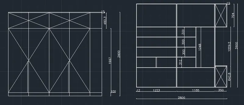
Front elevation
First change the units to millimeters and meters and decimal in UN enter
Invoke rec command and @2800,2600
Then use offset command and offset in parts as shown in the fig
By using line command do crossing of inverted lines as shown
By using DIMLIN command give dimensions
Car case dimensions
Invoke line command draw line in y axis of length 2600
The draw lines of 2800 length in x axis at both the ends
Use offset command and offse of 12 in y direstion
Then offset of 1223 and then 1200 and 360 on the x direction
Use offset command and do 12 from top and bottom in y axis
Then do offset of 680 from bottom and 488 from top
Then offset of 300 till down
After every offset give thickness offset as 12
Give hanger face at esyimated distance in between
Then give dist of 1200 in x and 580 in y direction
Then give top and bottom branches give lengths of 365 and 900 for first
And 368 and 500 for second
Trim the uncessary lines near the branches
Give dimensions as given using DIMLIN command
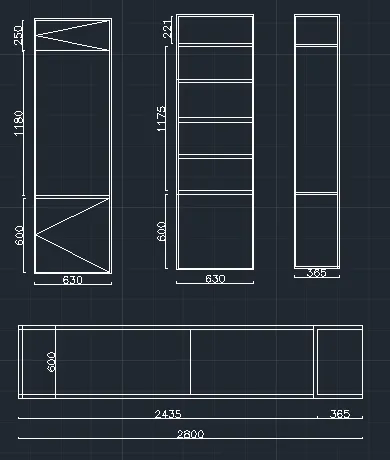
Side elevations
Invoke line command and draw the sections of lengths 2500 and 630 in all elevations
In section 2 give distance of 365
Use offset command and do offset of 900,1180 and 520
As shown in the fig
Give dimension by DIMLIN on in the ribbon of annotate tab
You can also give DIMCONTINUE command to give dimensions continuely
Plan
Invoke line command and draw 630 and 2800
Then use offset command and draw 365, 2436 units
Use dimlin command and give dimensions
2.
Aim- To draft the given drawings as in the figure with the dimensions given
Procedure-
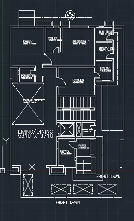
Firstly use XL command and draw horizontal and vertical lines at any point
The trim the opposide side of two lines where you wanted to draw
Mostlu offset command is used
Offset the outer walls as 230 as goven to the entire line
Then offset of the living and dining room for 5310 and 9710 (x&y)
Then offset inner walls of 150
Then offset for foyer and lift
AS the y axis in same dimension 2000 in x axis and divide
Foyer of 3220 and lift of 1600
Then offset inner walls 150
Then offset for patio and lumber room 2150 in x
Then divise lumber in 2150 and patio for 1570 as lift pit
Then Offset from living to power room and kitchen hence X is same as 1800
Divide power room of 1650
Then kitchen of 3200 in Y
Then the remaining portion is for stiars
Give riser of 1' and thread as 3'
Offset for family , toilet and bedroom1
Offset from x as 3880 for family , 1750 toilet and 3830 for bed room
Yaxis is 4350 for all and end give outer wall distance 230
Offset 1900 for DH toilet , utilty rooms
y axis offset is 1700 toilet, 2100 and 2150 for utility
Then for windows,doors and openings
Uline command and draw of approximate distances
Then give the openings using trim command
And also by using line command and offset command give cantilever projections wherever is necessary
Then draw the doors of line command and circle command and trim unnecessary lines
Then chane the line layer and use dotted or any other line and draw all the lawns and balconies which are given
Then use circle command fillet comand draw outdoow seating with canopy
Use DT enter command and give all rooms and dimensions which are necessary and shown in fig
3.
Aim- To draft the given drawings as in the figure with the dimensions given
Procedure-
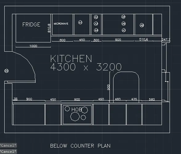
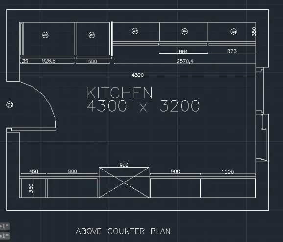
Use rec command and draw @4300,3200
Then give offset of 230 for outer walls
Give door openings using trim command
Draw doors using line and circle command
Then trim unnecessary lines
Draw windows as assumpted dimensions using line command
Then copy it since the outlook is same for above and below counter
For below counter
Use offset command and draw fridge of 1000 units and microvave as 600
A nd rest all as 450,300,900 as shown
Same for the above counter also
Give offset for chimney all the other blocks
A11 to A15
According to the drawings
Give dimensions using DIMLIN command
And names using DT command and specefy height as 4" and 0 rotaion
4.
Aim- To draft the given drawings as in the figure with the dimensions given
Procedure-
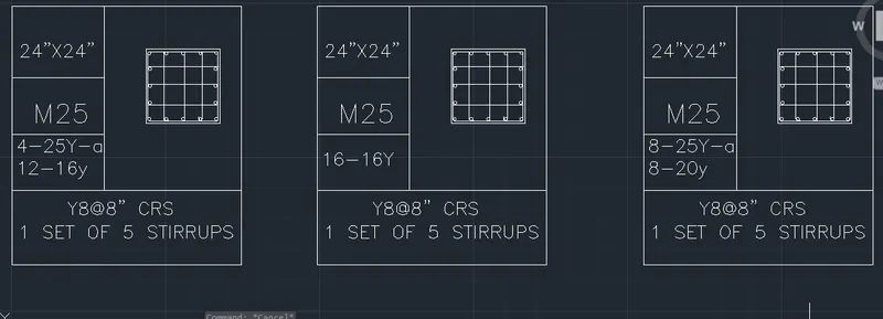
Use rectangle command and draw the give assumed dimensions and draw the table as in the figure
Then use same command and draw coloumn of sine @24",24"
Then by using circle command and draw reinforcement details
No of bars as 16
Then bu using line command give stirrups and hooks
Give detail of coloumn size and spacing and no of bars
Using th DT command
Copy in 3 copies and
Double click only on the no of bars colounn and you can edit it
5.
Aim- To draft the given drawings as in the figure with the dimensions given
Procedure-
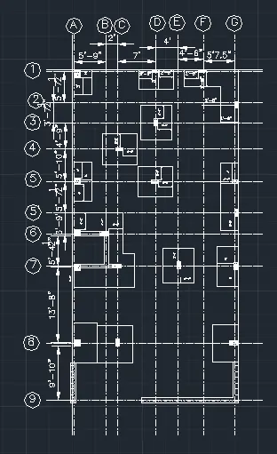
Firstly change units to architectural in feet and inches
Then Change layer in the ribbon
Use centreline layer for grids
Draw grids using offset and line command
First draw one horizontal and vertical XL line
Then offset from
X as 5'9",2',7',4',4.5',5'7.5"
Y as 5'7.5",3'7.5",4'9",5'10.5",5'7.5",3'9",13'10.5",10'4.5"
Then chamge the layer to any line
Name all the grids A,B,C..... in X direction and
1,2,3,4... in Y direction
Draw the coloumns by using rec command
The measurment of coloumns are taken assuming
Draw coloumns in 1,A grid then 1,D and 1,F
then 2,G
Then 3,D
Then 4,C
Then 5,A , 5,D , ,G
Then 5',G
Then 6,A and 6,B
Then in 7th row A,C,E and G
In 8th row A,C,G
Then give cover for all the coloumns using offset command ad fillet command of radius of 0
According to the drawing
By using the wall command draw wall thickness of 9"
Then give dimensions using DIMLIN command
DIMCONTINUE is used after first dimension so the dimensioning is done easily