Creating a Wardrobe detailed drawing, Floor Plan, Kitchen Layout and Column Detail using AutoCad
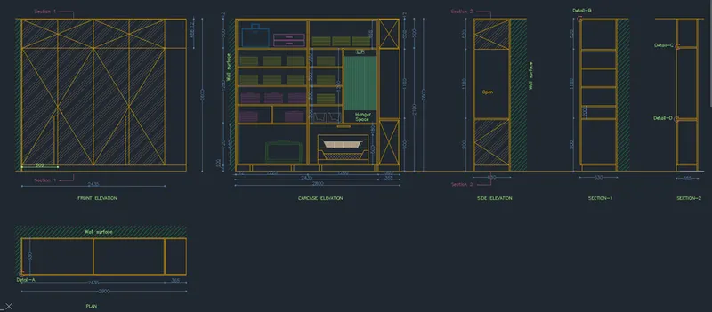
- Draw the elevation and details of a wardrobe as shown in the Figure below. After sketching, you need to provide the dimensions and text with the use of layers. Use proper text styles and dimension methods to document it. Also, assume dimensions, wherever needed.
Note: All dimensions are in mm.
Aim: To draw the elevation and details of a wardrobe using AutoCAD software.
Introduction:
Various commands used
- QNEW command
- UNIT command
- Line command
- Offset command
- Trim command
- Extend command
- Array command
- DIVIDE command
- Hatch command
- Dimlin command
- Dimcont command
Procedure:
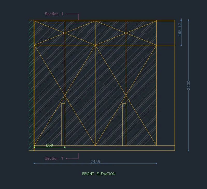
Drawing of front elevation
- Open AutoCAD software.
- Type QNEW in command box, press enter, and choose default setting as metric.
- Type UN in command box and press enter.
- Select the unit of measurement as decimal with the precision 0.
- Type REC in command box and press enter.
- Select the dimension option from command box.
- Specify length of rectangle as 2800 and width as 2600 units and press enter and click on the mouse.
- Type Explode in command, press enter and select the rectangle to explode.
- Type O in command box and press enter.
- Specify offset distance as 12 units and take offsets to the to and left side edges of rectangle in inner side.
- Type F in command box and press enter.
- Click on radius option from command box and specify fillet radius as 0 units, press enter and select the inner horizontal and vertical lines to fillet.
- Type O in command box, press enter, specify offset distance as 100, press enter, and take offset to the horizontal line in upward direction.
- Type O in command box, press enter, specify offset distance 365, press enter and take offset to the right edge of rectangle in left side.
- Type TR in command box and trim the extra line beyond the just drawn offset.
- Type DIVIDE in command box, press enter, select the second bottommost horizontal line.
- Specify number of segments as 4 and press enter.
- Type DDTYPE in command box, press enter select the cross mark sign as point style and select ok.
- Type L in command box and specify first point as just drawn point and draw vertical line in upward direction.
- Type CO in command box and press enter.
- Select just drawn vertical line, press enter, select the base point as bottom of vertical line and copy it to the position of points.
- Select the all points and erase it using the erase tool.
- Type H in command box and press enter.
- Select the hatch pattern as ANS134 with the scale of 10 and select ok.
- Pick the internal point as per requirement of hatch.
- Type L in command box and draw the lines wherever required.
Drawing the plan
- Type L in command box and press enter.
- Make sure ortho mode is on in the status bar.
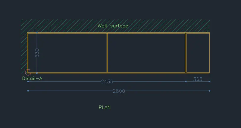
- Specify first point as bottom left corner and right corner of front elevation and extend it in downward direction.
- Type XL in command box and press enter.
- Select the horizontal option from command box and draw the horizontal line intersecting both extended vertical lines.
- Type TR in command box and trim the extra lines.
- Type O in command box, specify offset distance 630, press enter and take offset in downward direction from just drawn horizontal line rectangle is created.
- Type O in command box and press enter.
- Specify offset distance as 20 units and take offsets to the rectangle in inner side from all side expect from right edge of the rectangle.
- Type O in command box and press enter.
- Specify offset distance as 1212 units and take offsets to the rectangle in inner side from left edge of rectangle in right side.
- Type O in command box, press enter, specify offset distance 20, press enter and take offset to the right side to just drawn offset.
- Type O in command box, press enter, specify offset distance 365, press enter and take offset to the right edge of rectangle in left side.
- Type O in command box, press enter, specify offset distance 20, press enter and take offset to the right and left side to just drawn offset.
- Type TR in command box and trim the extra lines.
Drawing of Carecase
- Type REC in command box and press enter.
- Select the dimension option from command box.
- Specify length of rectangle as 2800 and width as 2600 units and press enter and click on the mouse.
- Type Explode in command, press enter and select the rectangle to explode.
- Type O in command box and press enter.
- Specify offset distance as 12 units and take offsets to the top and left side edges of rectangle in inner side.
- Type F in command box and press enter.
- Click on radius option from command box and specify fillet radius as 0 units, press enter and select the inner horizontal and vertical lines to fillet.
- Type O in command box, press enter, specify offset distance 365, press enter and take offset to the right edge of rectangle in left side.
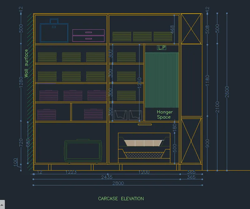
- Type rec in command box, press enter, specify first corner point as left side endpoint of second bottommost horizontal line, select the dimension option from command box, specify length as 1223 units and width as 2488 units and press enter.
- Move the cursor in first quadrant and click on the mouse.
- Again, type rec in command box, press enter, specify first corner point as bottom right corner of just drawn rectangle, select the dimension option from command box, specify length as 1200 units and width as 2488 units and press enter.
- Move the cursor in first quadrant and click on the mouse.
- Type O in command box, press enter.
- Specify offset distance as 20 units and take offsets to both rectangle in inner side.
- Type explode in command box, press enter and select the just drawn rectangle.
- Repeat the same procedure for second rectangle also.
- Type O in command box, press enter, specify offset distance 680, press enter and take offset to the bottom inner horizontal lines of both the rectangle.
- Again, type O in command box, press enter, specify offset distance 320, press enter and take 4 offsets to just taken offset in upward direction.
- Again, type O in command box, press enter, specify offset distance 20, press enter and take 4 offsets to just taken offset in upward direction.
- Using the line tool and offset tool draw the shelves to the carcase in the elevation.
- From the rightmost edge of second rectangle take offset of 20 units in the right side.
- Type REC in command box and press enter and specify first corner point as right bottom corner of second rectangle.
- Select the dimension option, specify length 365, width as 800 units, press enter and move cursor in first quadrant and click on mouse.
- Join the diagonals of just drawn rectangle using the line tool.
- Similarly using the rectangle tool draw the rectangle of size 365 x 508 units.
- Type O in command box and take offset of 20 units in inner side of rectangle.
- Join the diagonals of rectangle by using the line tool.
- Type TR in command box and trim the extra lines.
Drawing of Side Elevation
- Type REC in command box and press enter.
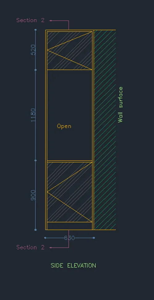
- Select the dimension option from command box, specify length as 630 units and width as 2600 units and press enter.
- Move the cursor in first quadrant and click on the mouse.
- Type explode in command box, press enter and select the rectangle.
- Type O in command box and press enter.
- Specify offset distance as 20 units and take offsets to the rectangle in inner side from all side expect from bottom edge of the rectangle.
- Again, type O in command box, press enter, specify offset distance 100, press enter and take offset from bottom edge of rectangle in inner side.
- Type O in command box, press enter, specify offset distance 900, press enter and take offset from bottom edge of rectangle in inner side.
- Type O in command box, press enter, specify offset distance 20, press enter and take offset from just drawn line in downward direction.
- Type O in command box, press enter, specify offset distance 1180, press enter and take offset from the same line in upward direction.
- Type H in command box and draw the hatch wherever required by same procedure with appropriate scale as mentioned above.
- Using the line tool draw the lines wherever required.
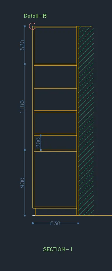
Drawing of section-1
- Type REC in command box and press enter.
- Select the dimension option from command box, specify length as 630 units and width as 2600 units and press enter.
- Move the cursor in first quadrant and click on the mouse.
- Type explode in command box, press enter and select the rectangle.
- Type O in command box and press enter.
- Specify offset distance as 20 units and take offsets to the rectangle in inner side from all side expect from bottom edge of the rectangle.
- Again, type O in command box, press enter, specify offset distance 100, press enter and take offset from bottom edge of rectangle in inner side.
- Type O in command box, press enter, specify offset distance 900, press enter and take offset from bottom edge of rectangle in inner side.
- Type O in command box, press enter, specify offset distance 20, press enter and take offset from just drawn line in downward direction.
- Type O in command box, press enter, specify offset distance 200, press enter and take offset from the same line.
- Type O in command box, press enter, specify offset distance 20, press enter and take offset from just drawn line in upward direction.
- Type O in command box, press enter, specify offset distance 300, press enter and take offset from just drawn line in upward direction.
- Type O in command box, press enter, specify offset distance 20, press enter and take offset from just drawn line in upward direction.
- Type O in command box, press enter, specify offset distance 300, press enter and take offset from just drawn line in upward direction.
- Type O in command box, press enter, specify offset distance 20, press enter and take offset from just drawn line in upward direction.
- Type O in command box, press enter, specify offset distance 300, press enter and take offset from just drawn line in upward direction.
- Type O in command box, press enter, specify offset distance 20, press enter and take offset from just drawn line in upward direction.
- Type TR in command box and trim the extra lines.
Drawing section-2
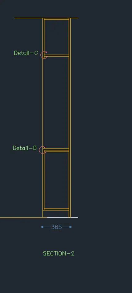
- Type REC in command box and press enter.
- Select the dimension option from command box, specify length as 365 units and width as 2600 units and press enter.
- Move the cursor in first quadrant and click on the mouse.
- Type explode in command box, press enter and select the rectangle.
- Type O in command box and press enter.
- Specify offset distance as 20 units and take offsets to the rectangle in inner side from all side expect from bottom edge of the rectangle.
- Again, type O in command box, press enter, specify offset distance 100, press enter and take offset from bottom edge of rectangle in inner side.
- Type O in command box, press enter, specify offset distance 20, press enter and take offset from just drawn line in upward direction.
- Type O in command box, press enter, specify offset distance 900, press enter and take offset from bottom edge of rectangle in inner side.
- Type O in command box, press enter, specify offset distance 20, press enter and take offset from just drawn line in downward direction.
- Type O in command box, press enter, specify offset distance 20, press enter and take offset from just drawn line in downward direction.
- Type O in command box, press enter, specify offset distance 520, press enter and take offset from top horizontal inner horizontal line.
- Type ST in command box, select the font name as romans, height of text as 50 units and select ok.
- Type MTEXT in command box and press enter.
- Specify first corner point and type the text content.
- Select the text and copy it to required position using the copy tool from the ribbon of home tab.
- Type ED in command box and press enter.
- Choose the multiple option from the command box and edit the all text as per required content.
- Type dimlin in command box and press enter.
- Specify first extension line origin and second line extension origin and give the dimensions to all the lines.
- Type DIMCONT in command box, press enter.
- Select the dimension which is required to be continued and continue the dimensions.
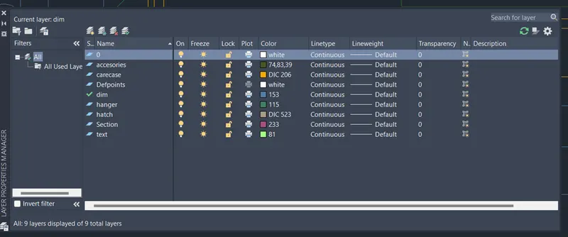
- Type LA in command box and press enter.
- Add the different layers by giving the specific names to each layer and assigning them different colors in layer dialog box.
- Select the objects of drawing having similar function and add it to the respective layers as shown in the fig.
Result: elevation and details of a wardrobe is drawn using AutoCAD software by following above procedure is shown below.
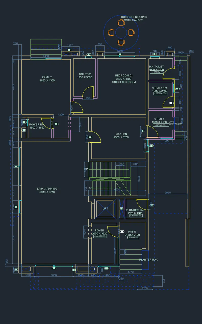
2. Draw the floor plan as shown in the Figure. Use the proper drafting tools to sketch the plan. Do not hatch or draw the furniture. You need to draw the floor plan with the following:
Note: You can also import the Floor_Plan.pdf into your current drawing and start working on the project. You need to scale the imported pdf file using reference option. All dimensions are in mm.
- Walls (Exterior and Interior)
Wall Thickness: Exterior Wall- 230mm, Interior Wall: 150 mm (Wherever Required)
- Doors and Windows: Assume the size of the doors and window.
2.1 Stairs: Tread-300mm, Riser-150mm
- Insert Text wherever required
- insert dimensions using proper dimension techniques.
Aim: to draw the floor plan using AutoCAD software.
Introduction:
Various commands used
- QNEW command
- UN command
- Line command
- Offset command
- XL command
- Trim command
- Fillet command
- Extend command
- Mtext command
- ED command
- LA command
- Circle command
- Rectangle command
- Copy command
- Move command
- DIMLIN command
- DIMCON command
Procedure:
- Type XL in command box and press enter.
- Choose horizontal option from command box and draw the horizontal line.
- Again type the XL in command box and press enter.
- Choose vertical option from command box and draw the vertical line.
- Type TR in command box and trim the lines to create the corner.
- Type O in command box and press enter.
- Specify offset distance 230 units and take offset the both the lines.
- Type F in command box and press enter.
- Select the radius option and specify radius 0 units and select lines as inner lines.
- Type O in command box, press enter, specify offset distance 5310 units, press enter and take offset from inner vertical line in right direction.
- Type O in command box, press enter, specify offset distance 230 units, press enter and take offset from just drawn offset line in right direction.
- Type O in command box, press enter, specify offset distance 2000 units, press enter and take offset from just drawn offset line in right direction.
- Type O in command box, press enter, specify offset distance 230 units, press enter and take offset from just drawn offset line in right direction.
- Type O in command box, press enter, specify offset distance 2150 units, press enter and take offset from just drawn offset line in right direction.
- Type O in command box, press enter, specify offset distance 150 units, press enter and take offset from just drawn offset line in right direction.
- Using the trim tool trim the extra lines to create the wall joint.
- Type O in command box, press enter, specify offset distance 3220 units, press enter and take offset from bottom inner horizontal line in upward direction.
- For creating the opening, type O in command box, press enter, specify offset distance 2020 units, press enter and take offset from inner bottom horizontal line.
- Type O in command box, press enter, specify offset distance 1000 units, press enter and take offset from just drawn offset line in upward direction.
- Using trim tool trim the extra lines.
- Type O in command box, press enter, specify offset distance 1600 units, press enter and take offset from just drawn offset line in upward direction.
- Type O in command box, press enter, specify offset distance 230 units, press enter and take offset from just drawn offset line in upward direction.
- Using trim tool trim the extra lines.
- For drawing the plumber room, type O in command box, press enter, specify offset distance 1570 units, press enter and take offset from right second most vertical line in left direction.
- Type O in command box, press enter, specify offset distance 150 units, press enter and take offset from just drawn offset line in left direction.
- Type O in command box, press enter, specify offset distance 394 units, press enter and take offset from just drawn offset line in left direction.
- Type O in command box, press enter, specify offset distance 230 units, press enter and take offset from just drawn offset line in left direction.
- Type O in command box, press enter, specify offset distance 1726 units, press enter and take offset from just drawn offset line in left direction.
- Type O in command box, press enter, specify offset distance 230 units, press enter and take offset from just drawn offset line in left direction.
- Type O in command box, press enter, specify offset distance 2700 units, press enter and take offset from top horizontal line in upward direction.
- Type O in command box, press enter, specify offset distance 230 units, press enter and take offset from just drawn offset line in upward direction.
- Type O in command box, press enter, specify offset distance 3200 units, press enter and take offset from just drawn offset line in upward direction.
- Type O in command box, press enter, specify offset distance 230 units, press enter and take offset from just drawn offset line in upward direction.
- Type O in command box, press enter, specify offset distance 4500 units, press enter and take offset from just drawn offset line in upward direction.
- Type O in command box, press enter, specify offset distance 230 units, press enter and take offset from just drawn offset line in upward direction.
- Type F in command box and press enter.
- Choose multiple option from command box and select the inner left side vertical and inner top horizontal line followed by inner right vertical line and second top most horizontal line for creatin top inner corners of plan.
- Similarly select the external lines to create the outer face of wall.
- Using trim tool trim the extra unwanted lines to crate wall joints.
- Type O in command box, press enter, specify offset distance 3830 units, press enter and take offset from inner right vertical line in left direction.
- Type O in command box, press enter, specify offset distance 150 units, press enter and take offset from just drawn offset line in left direction.
- Type O in command box, press enter, specify offset distance 1750 units, press enter and take offset from just drawn offset line in left direction.
- For drawing the toilet-1, type O in command box, press enter, specify offset distance 1750 units, press enter and take offset from inner top horizontal line in downward direction.
- Type O in command box, press enter, specify offset distance 150 units, press enter and take offset from just drawn offset line in upward direction.
- For drawing the opening draw offset of 150 units from right inner wall of toilet-1 followed by offset of 875 units
- Using trim tool trin the extra lines to create the opening for toilet 1.
- From inner top horizontal line of left side take offset of 300 units in downward direction to create wall of family room 300 unit thick.
- Type O in command box, press enter, specify offset distance 4350 units, press enter and take offset from just drawn offset line in downward direction.
- Type O in command box, press enter, specify offset distance 150 units, press enter and take offset from just drawn offset line in downward direction.
- Type O in command box, press enter, specify offset distance 1650 units, press enter and take offset from just drawn offset line in downward direction.
- Using trim tool, trim the extra lines to crate wall joints.
- For creating the opening to bedroom draw the offset of 1150 in upward direction from bottom inner face of wall.
- Using trim tool trim extra lines to create opening.
- From the thickness of opening take offset of 1000 units in downward direction and create portion of wall using line tool.
- Type PL in command box and press enter.
- Specify first point as bottom left corner of thickness of opening and draw line of 70 unit length in downward direction followed by horizontal line of 90 unit length followed by 40 unit length in upward direction followed by 40 unit length in right direction followed by length of 30 units in upward direction.
- Copy the polyline using copy tool.
- Type RO in command box and press enter.
- Select the polyline and press enter.
- Select base point as left corner point specify rotation angle as 180 and press enter.
- Type MOVE in command box and move it to the appropriate position.
- Using line tool draw the line by specifying first point as top right corner of bottom face of opening in upward direction followed by horizontal line in right direction.
- Type O in command box, press enter, specify offset distance 30 units, press enter and take offset to just drawn line in downward direction.
- Type C in command box and press enter.
- Select the center as top right corner of polyline and draw the circle.
- Using trim tool trim the extra portion of circle.
- Similarly draw the all opening.
- For creating opening for family room take offset of 1200 units from right inner wall of family room.
- And trim it to create the opening.
- From left face of opening draw the vertical line in downward direction and take offset to the same line in left direction to the same line.
- Type O in command box, press enter, specify offset distance 1800 units, press enter and take offset from just drawn offset line in left direction.
- Type O in command box, press enter, specify offset distance 230 units, press enter and take offset from just drawn offset line in left direction.
- Type O in command box, press enter, specify offset distance 725 units, press enter and take offset from inner right face of wall of family room.
- Type EXTEND in command box and extend the line in upward direction.
- Type O in command box, press enter, specify offset distance 2430 units, press enter and take offset from just drawn offset line in left direction.
- Using trim tool trim extra lines and create opening.
- Using line tool join the inner face of opening.
- Type O in command box, press enter, specify offset distance 400 units, press enter and take four offset from just drawn line in upward direction it will create the stairs.
- Type O in command box, press enter, specify offset distance 1900 units, press enter and take offset from right side outer vertical line in right direction.
- Type O in command box, press enter, specify offset distance 150 units, press enter and take offset from just drawn offset line in right direction.
- Type F in command box and press enter.
- Select the inner and outer vertical and horizontal and vertical lines respectively to create the top right corner of plan.
- Using trim tool trim the wall joint.
- Type O in command box, press enter, specify offset distance 1700 units, press enter and take offset from second topmost horizontal line of top right corner in downward direction.
- Type O in command box, press enter, specify offset distance 150 units, press enter and take offset from just drawn offset line in downward direction.
- Type O in command box, press enter, specify offset distance 2100 units, press enter and take offset from just drawn offset line in downward direction.
- Type O in command box, press enter, specify offset distance 150 units, press enter and take offset from just drawn offset line in downward direction.
- Type O in command box, press enter, specify offset distance 2150 units, press enter and take offset from just drawn offset line in downward direction.
- Using trim tool trim the extra lines.
- Type O in command box, press enter, specify offset distance 1000 units, press enter and take offset from right most vertical line in right direction.
- Type O in command box, press enter, specify offset distance 230 units, press enter and take offset from just drawn offset line in right direction.
- Type EX in command box and extend the line to create the continuous lines.
- For creating the steps use offset tool and specify offset distance as 300 units.
- For creating the stairs type O in command box, press enter, specify offset distance 2700 units, press enter and take offset from inner side wall in left direction.
- Type O in command box, press enter, specify offset distance 300 units, press enter and take offset from just drawn offset line in left direction.
- By using the rectangle tool draw the rectangle of size 3300 x 300 units and place it with midpoint coinciding with midpoint of landing slab.
- Type O in command box, press enter, specify offset distance 50 units, press enter and take offset in inner side of rectangle.
- Using line tool join the diagonals of rectangle and trim unwanted projections using trim tool.
- Ty LT in command box, press enter and select line type as ISO03W100 and draw the hidden slabs.
- Type ST in command box, select the font name as romans, height of text as 50 units and select ok.
- Type MTEXT in command box and press enter.
- Specify first corner point and type the text content.
- Select the text and copy it to required position using the copy tool from the ribbon of home tab.
- Type ED in command box and press enter.
- Choose the multiple option from the command box and edit the all text as per required content.
- Type dimlin in command box and press enter.
- Specify first extension line origin and second line extension origin and give the dimensions to all the lines.
- Type DIMCONT in command box, press enter.
- Select the dimension which is required to be continued and continue the dimensions.
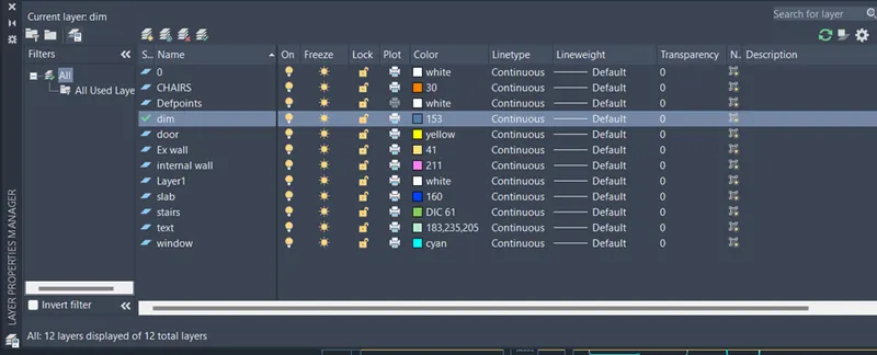
- Type LA in command box and press enter.
- Add the different layers by giving the specific names to each layer and assigning them different colors in layer dialog box.
- Select the objects of drawing having similar function and add it to the respective layers as shown in the fig.
Result: Floor plan is drawn using AutoCAD software by following above procedure is shown below.
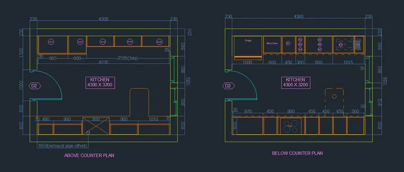
3. Create the Kitchen Layout as shown in the Figure below. Also, use proper dimension techniques to dimension the kitchen layout. Also, insert text wherever required. All dimensions are in mm.
Aim: To draw the kitchen layout using AutoCAD software.
Introduction:
- Various commands used
- QNEW command
- UN command
- REC command
- Offset command
- Explode command
- Circle command
- Line command
- Ed command
- Mtext command
- LA command
- DIMLIN command
- DIMCONT command
- Trim command
- Extend command
Procedure
- Open AutoCAD software.
- Type QNEW in command box, press enter, and choose default setting as metric.
- Type UN in command box and press enter.
- Select the unit of measurement as architecture with the precision 0.
- Type REC in command box and press enter.
- Click on dimension option, specify length as 4300 and width as 3200 , press enter and draw the rectangle.
- Take offset of 230 mm in external side to the rectangle.
- Type explode in command box, press enter and explode the inner rectangle.
- For drawing the opening, draw the line at midpoint of left edge of rectangle inside the thickness.
- Take offset of 500 units to both side of just drawn line.
- Trim the lines to create opening using trim tool.
- For drawing the hinge choose polyline tool and specify first point as corner point of opening, draw the line in vertical direction of 70 unit length followed by horizontal line of 90 unit length, followed by 40 unit length downward line followed by 40 unit length horizontal line in right direction followed by downward line of 30 unit length.
- From the midpoint of thickness draw the vertical line of 60 unit length using line tool, followed by horizontal line in right direction.
- Draw the door using circle tool and trim the extra portion of circle.
- For drawing the window take offset of 600 units in upward direction to bottom inner horizontal line.
- Draw the hinge using polyline tool.
- For that draw vetical line of 30 unit length followed by horizontal line of 120 unit length followed by 10 unit length downward line followed by horizontal line of 110 unit length followed by 20unit length vertical line.
- Draw the four rectangles of 45 x 45 unit size and place it at appropriate positions and join the midpoints of rectangle using line tool.
- Similarly draw the second window.
- Take offset of 600 units to the inner bottom horizontal line in upward direction.
- Extend line in thickness of wall and trim the extra line.
- Using line tool draw the horizontal line in right direction of 600 unit length followed by 900 unit vertical line followed by 600 unit length horizontal line followed by vertically downward line of 900 unit length followed by horizontal line intersecting vertical inner face of wall.
- Type CO in command box, press enter, specify base point and copy whole drawing.
- By using the offset tool, trim tool and line tool draw the kitchen assesories.
- Type ST in command box, select the font name as romans, height of text as 50 units and select ok.
- Type MTEXT in command box and press enter.
- Specify first corner point and type the text content.
- Select the text and copy it to required position using the copy tool from the ribbon of home tab.
- Type ED in command box and press enter.
- Choose the multiple option from the command box and edit the all text as per required content.
- Type dimlin in command box and press enter.
- Specify first extension line origin and second line extension origin and give the dimensions to all the lines.
- Type DIMCONT in command box, press enter.
- Select the dimension which is required to be continued and continue the dimensions.
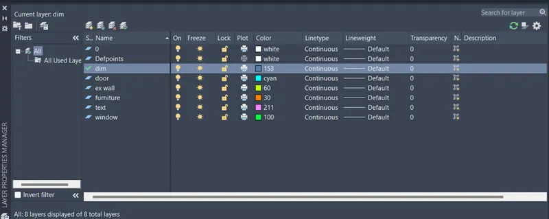
- Type LA in command box and press enter.
- Add the different layers by giving the specific names to each layer and assigning them different colors in layer dialog box.
- Select the objects of drawing having similar function and add it to the respective layers as shown in the fig.
Result: Kitchen layout is created using AutoCAD software by following above procedure is shown below.
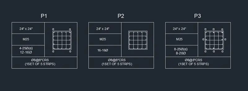
- Sketch the column details as shown in Figure. Insert dimensions and text in the figure. Refer to the bar sizes from the schedule.
8mm ---- 0.31 Inches
25mm--- 1 inches
16mm—0.62 inches
Aim: To draw the column details using AutoCAD software.
Introduction:
Various commands used
- QNEW command
- UN command
- Line command
- Offset command
- DDPTYPE command
- DIVIDE command
- Circle command
- Hatch command
- Erase command
- Copy command
- Rotate command
- Trim command
- Offset command
- Mtext command
Procedure
- Open AutoCAD software.
- Type QNEW in command box, press enter, and choose default setting as imperial.
- Type UN in command box and press enter.
- Select the unit of measurement as architecture with the precision 0’-0”.
- Type REC in command box and press enter.
- Select the dimension option from command box.
- Specify length of rectangle as 24” and width as 24” units and press enter and click on the mouse.
- Take offset of 1” to the inner side of rectangle.
- Type EXPLODE in command box; press enter and select the inner rectangle to explode.
- Type DIVIDE in command box, press enter and select the width of rectangle.
- Enter number of segments to divide as 4 and press enter.
- Type DDPTYPE in command box, press enter and change the point style so that it can easily visible.
- For drawing the rebars in column from the ribbon in home tab select the circle tool and in that select tangent, tangent and radius option.
- Select first tangent as top length, second tangent as left side width of inner rectangle and specify radius as 0.5” and press enter.
- Type H in command box and press enter.
- Select the solid hatch pattern and pick internal point as center of circle.
- Type MIR in command box and select object as just drawn circle and press enter.
- Select first mirror point as midpoint of left side width and second mirror point as center of rectangle it will create the rebars.
- Make sure that visibility of center, geometric center, midpoint, endpoint, quadrant, node and tangent is on in object snap setting.
- Type co in command box, press enter and select the left top corner circle along with hatch.
- Press enter and select base point as left quadrant of first circle and copy it in the position of points and press escape.
- Select the points and erase it using erase tool.
- Type MIR in command box, press enter, select the left part of rectangle and press enter.
- Select the copy tool and copy the circles at their required position
- For drawing the hook, Type CO in command box, press enter.
- Select any one drawn circle and copy it to outside the rectangle.
- Using line tool draw the vertical lines of 0.5” length from two opposite quadrants of circle.
- Type TR in command box and trim the inner arc of the circle.
- Type Ro in command box, select just drawn hook and press enter.
- Select the base point as center of circle as and specify base point as center of circle.
- Specify the required rotation angle and rotate it to required position.
- Similarly draw the P2 and P3 with the variation of size of diameter of circle.
- Draw the table for content using rectangle and line tool.
- Type ST in command box, select the font name as romans, height of text as 3” units and select ok.
- Again, create the new text style of 5” height and use it for heading of the tables,
- Type MTEXT in command box and press enter.
- Specify first corner point and type the text content.
- Select the text and copy it to required position using the copy tool from the ribbon of home tab.
- Type ED in command box and press enter.
- Choose the multiple option from the command box and edit the all text as per required content.
Result: the column details using AutoCAD software by following above procedure is shown below.
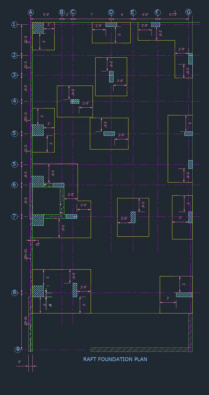
- Draw the Raft Layout as shown in the Figure. Assume the column size as per your knowledge. You can take the sizes as: 24”x24”, 9” x 24”, 9” x 18”, and 9’ x 24”. You can import the raft_foundation.pdf to ensure the missing dimensions.
Aim: to draw the raft layout using AutoCAD software.
Introduction:
Various commands used
- QNEW command
- UN command
- LT command
- Offset command
- XL command
- Offset command
- REC command
- H command
- ST command
- MTEXT command
- ED command
- Copy command
- Fillet command
- DIMLIN command
- DIMCON command
- LA command
Procedure:
- Open AutoCAD software.
- Type QNEW in command box, press enter, and choose default setting as imperial.
- Type UN in command box and press enter.
- Select the unit of measurement as architectural with the precision 0’0(1/2)”.
- Using XL command draw the two vertical and two horizontal lines and trim the extra lines using trim tool creating the rectangular box.
- Type O in command box, press enter, specify offset distance 5’-9” units, press enter and take offset to vertical line in right direction.
- Type O in command box, press enter, specify offset distance 2’ units, press enter and take offset from just drawn offset line in right direction.
- Type O in command box, press enter, specify offset distance 7’ units, press enter and take offset from just drawn offset line in right direction.
- Type O in command box, press enter, specify offset distance 4’ units, press enter and take offset from just drawn offset line in right direction.
- Type O in command box, press enter, specify offset distance 4’-6” units, press enter and take offset from just drawn offset line in right direction.
- Type O in command box, press enter, specify offset distance 5’-7.5” units, press enter and take offset from just drawn offset line in right direction.
- Type O in command box, press enter, specify offset distance 10’-4.5” units, press enter and take offset to horizontal line in upward direction.
- Type O in command box, press enter, specify offset distance 13’-10.5” units, press enter and take offset from just drawn offset line in upward direction.
- Type O in command box, press enter, specify offset distance 5’-9”” units, press enter and take offset from just drawn offset line in upward direction.
- Type O in command box, press enter, specify offset distance 3’-9” units, press enter and take offset from just drawn offset line in upward direction.
- Type O in command box, press enter, specify offset distance 5’-7.5”” units, press enter and take offset from just drawn offset line in upward direction.
- Type O in command box, press enter, specify offset distance 5’-10.5”” units, press enter and take offset from just drawn offset line in upward direction.
- Type O in command box, press enter, specify offset distance 4’-9” units, press enter and take offset from just drawn offset line in upward direction.
- Type O in command box, press enter, specify offset distance 3’-7.5” units, press enter and take offset from just drawn offset line in upward direction.
- Type O in command box, press enter, specify offset distance 5’-7.5” units, press enter and take offset from just drawn offset line in upward direction.
- Type O in command box, press enter, specify offset distance 4.5” units, press enter and take offset from leftmost vertical line in right direction.
- Type LT in command box and press enter.
- Select the load option and load the centerline from line type dialog box.
- Select all the vertical and horizontal line expect second left vertical line change the line type to centerline.
- Type REC in command box, press enter, select dimension option from command box, specify length as 2’, width as 2’ and press enter and draw the rectangle.
- Type CO in command box and press enter.
- Select rectangle, press enter, specify base point and copy it to the required position.
- Similarly draw rectangles of 1’6” x 9” size and rectangle of 2’ x 9” size and copy it to required position using copy tool.
- For drawing the footing, type explode in command box and explode the rectangles.
- Take offset of required distance outside the rectangles which acts as column.
- Type F in command box, press enter, select the multiple option, select the radius option and specify radius as 0 units and fillet the lines to create the corners of footing.
- Type H in command box and select the ANS137 hatch pattern with the scale of 1.
- Pick the internal point as center of all the rectangles and fill it with the hatch.
- Using the line tool draw the lines to the required position.
- Type ST in command box, select the font name as romans, height of text as 8” units and select ok.
- Type MTEXT in command box and press enter.
- Specify first corner point and type the text content.
- Draw the small circle to insert the text within it.
- Select the text along with the circle and copy it to required position using the copy tool from the ribbon of home tab.
- Type ED in command box and press enter.
- Choose the multiple option from the command box and edit the all text as per required content.
- Type dimlin in command box and press enter.
- Specify first extension line origin and second line extension origin and give the dimensions to all the lines.
- Type DIMCONT in command box, press enter.
- Select the dimension which is required to be continued and continue the dimensions.
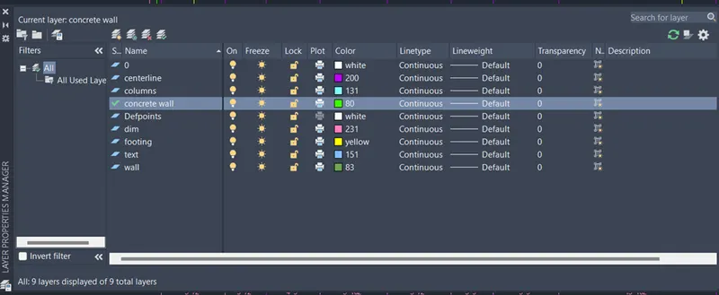
- Type LA in command box and press enter.
- Add the different layers by giving the specific names to each layer and assigning them different colors in layer dialog box.
- Select the objects of drawing having similar function and add it to the respective layers as shown in the fig.
Result: The raft layout using AutoCAD software by following above procedure is shown below.
.