Creating a Wardrobe detailed drawing, Floor Plan, Kitchen Layout and Column Detail using AutoCad
Q1
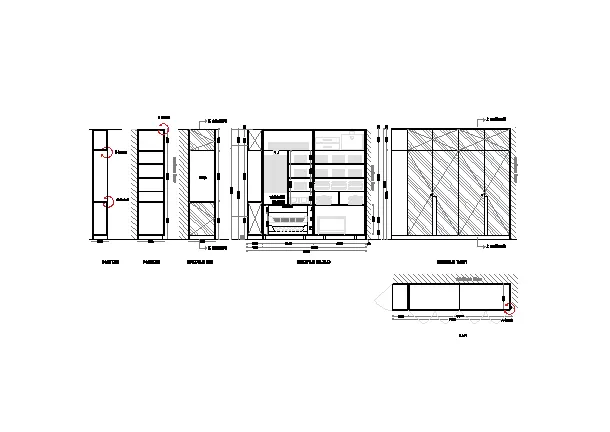
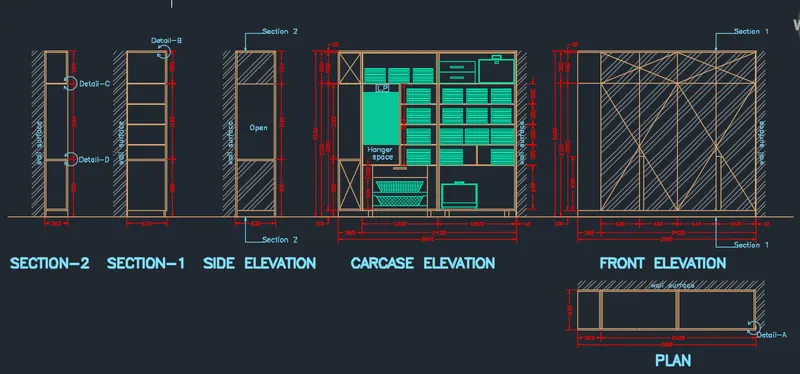
AIM : To draw the elevation and details of a wardrobe as shown in figure
PROCEDURE
STEP 1 :
Type unit or UN in the command box and press enter
Set type of unit as decimal and precision as 0
In Insertion scale set unit as Millimetres
STEP 2 :
Type dimension style manager or D in the command box and press enter
Modify primary units as decimal and precision as 0
STEP 3 :
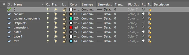
Type layer or LA in the command box and press enter
Create new layers according to drawing given
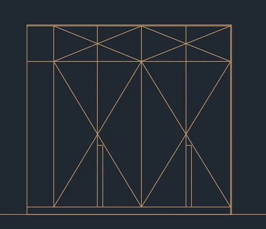
STEP 4 :
Using line command and offset command draw the front elevation of the wardrobe
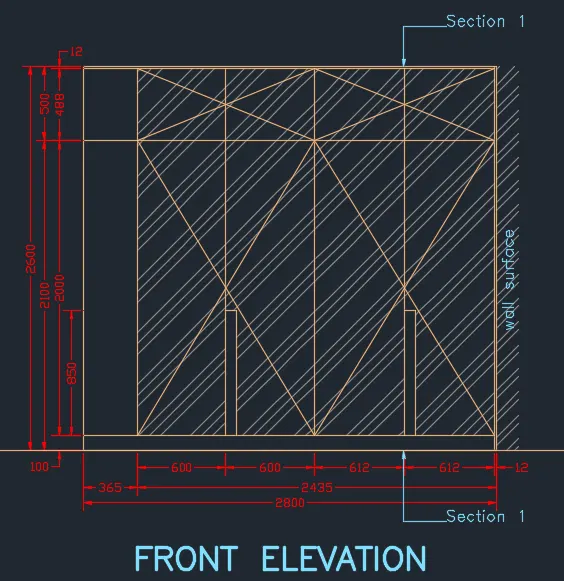
STEP 5 :
Using hatch command, dimension command and text command complete the front elevation of the wardrobe
STEP 6 :
Using line command, offset command draw the carcase elevation of the wardrobe
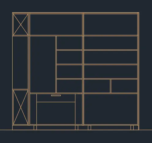
STEP 7 :
Using line command draw the components in carcase elevation of the wardrobe
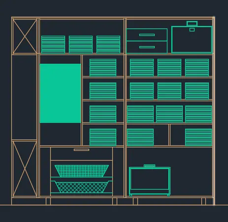
STEP 8 :
Using hatch command, dimension command and text command complete the carcase elevation of the wardrobe
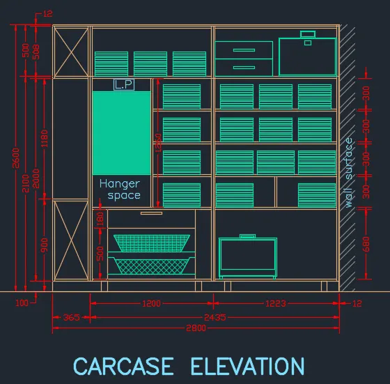
STEP 9 :
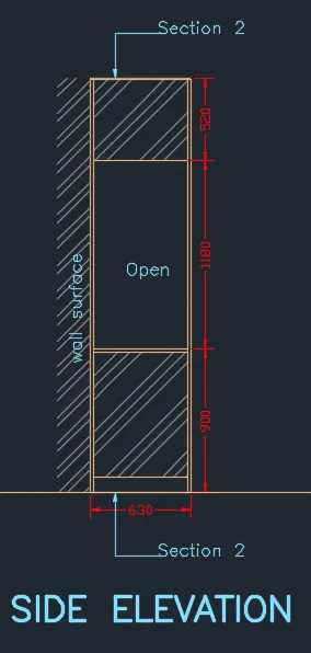
Using line command draw the side elevation of the wardrobe
Using hatch command, dimension command and text command complete the side elevation of the wardrobe
STEP 10 :
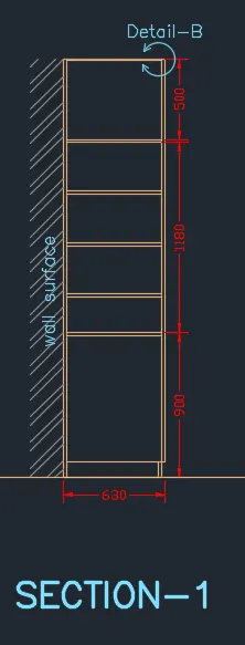
Using line command draw the section 1 of the wardrobe
Using hatch command, dimension command and text command complete the section 1 of the wardrobe
STEP 11 :
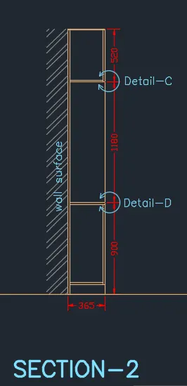
Using line command draw the section 2 of the wardrobe
Using hatch command, dimension command and text command complete the section 2 of the wardrobe
STEP 12 :
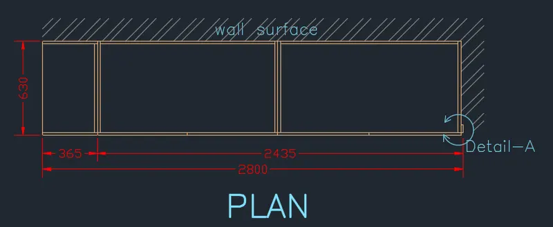
Using line command draw the plan of the wardrobe
Using hatch command, dimension command and text command complete the plan of the wardrobe
RESULT
The Given figure is drawn using necessary tools in AutoCAD
Q2
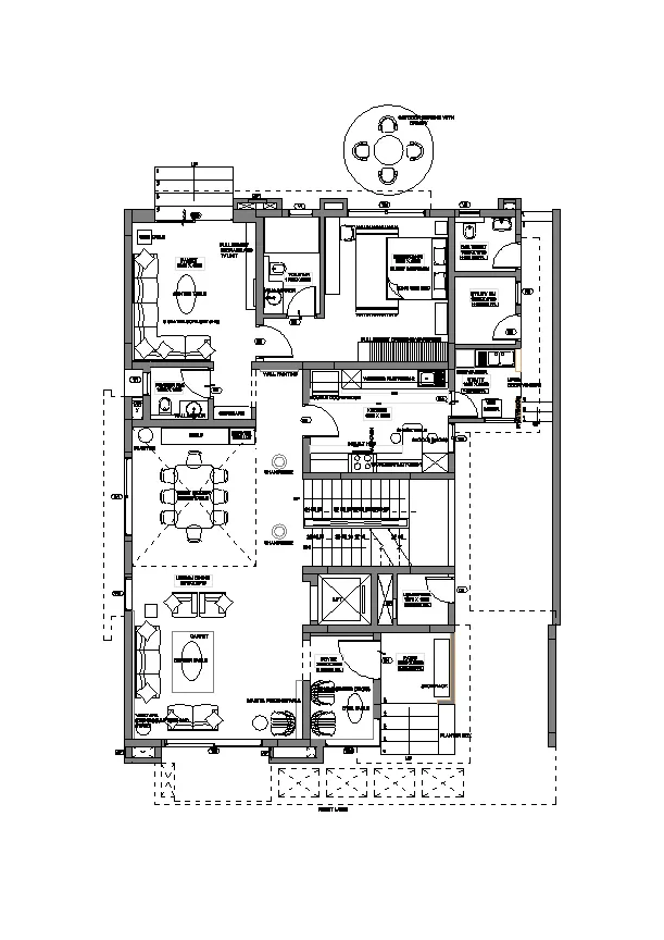
AIM : To draw the floor plan as shown in figure
PROCEDURE
STEP 1 :
Type unit or UN in the command box and press enter
Set type of unit as decimal and precision as 0
In Insertion scale set unit as Millimetres
STEP 2 :
Type dimension style manager or D in the command box and press enter
Modify primary units as decimal and precision as 0
STEP 3 :
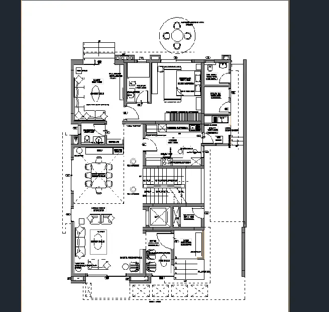
Go to Insert and Import the pdf and scale the drawing
RESULT
The Given figure is drawn using necessary tools in AutoCAD
Q3
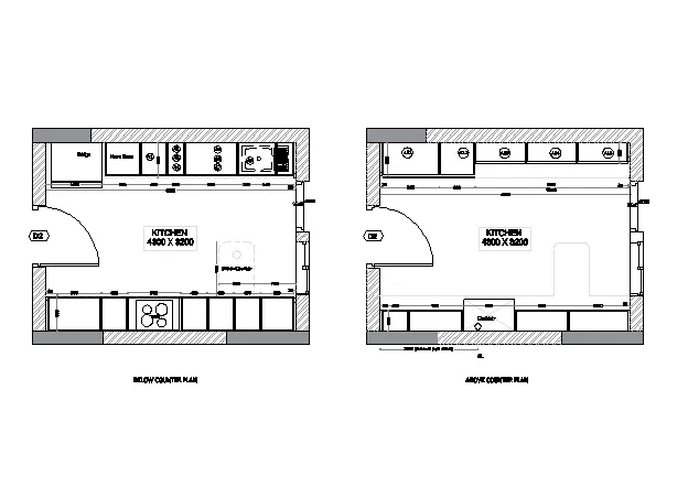
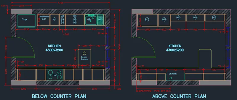
AIM : To draw the kitchen layout as shown in figure
PROCEDURE
STEP 1 :
Type unit or UN in the command box and press enter
Set type of unit as decimal and precision as 0
In Insertion scale set unit as Millimetres
STEP 2 :
Type dimension style manager or D in the command box and press enter
Modify primary units as decimal and precision as 0
STEP 3 :
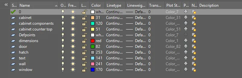
Type layer or LA in the command box and press enter
Create new layers according to drawing given
STEP 4 :
Using line command, offset command, trim command and dimension command draw the layout plan of the kitchen
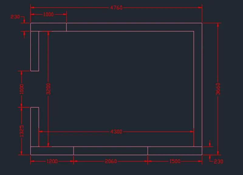
STEP 5 :
Using line command, arc command, trim command and dimension command draw the door and window of the kitchen
Using hatch command hatch the walls
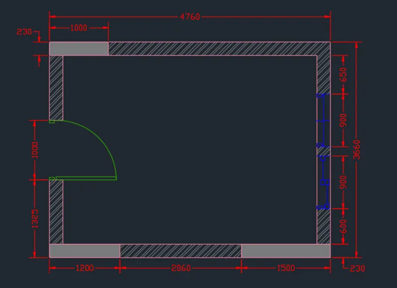
STEP 6 :
Using line command, offset command, trim command and dimension command draw the cabinet in the Kitchen layout
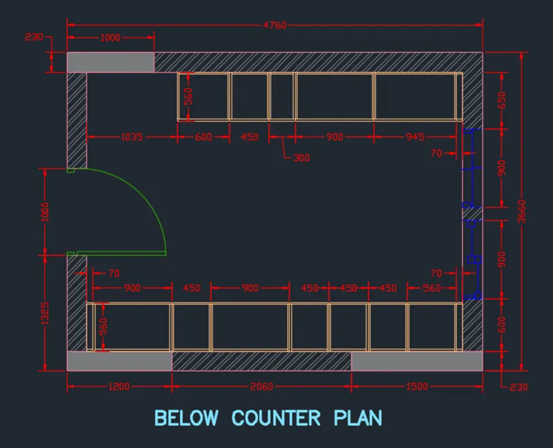
STEP 7 :
Using line command, offset command, text command and dimension command draw the cabinet counter top and cabinet components in the Kitchen layout
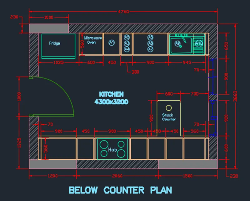
STEP 8 :
Copy the kitchen layout which was drawn for below counter unit
Using line command, offset command, trim command, text command and dimension command draw the above counter plan in the Kitchen layout
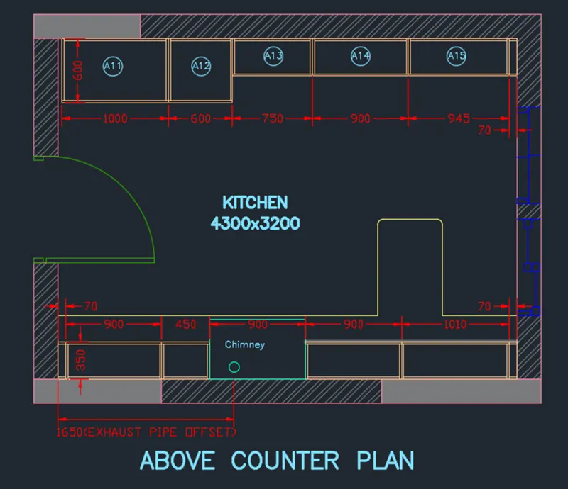
RESULT
The Given figure is drawn using necessary tools in AutoCAD
Q4
AIM : To draw the column detail as shown in figure
PROCEDURE
STEP 1 :
Type unit or UN in the command box and press enter
Set type of unit as engineering and precision as 0’-0”
In Insertion scale set unit as inches
STEP 2 :
Type dimension style manager or D in the command box and press enter
Modify primary units as engineering and precision as 0’-0”
STEP 3 :
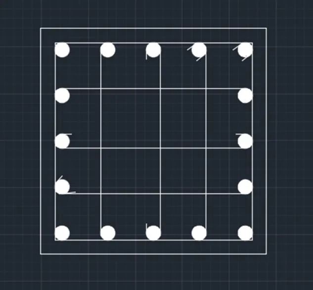
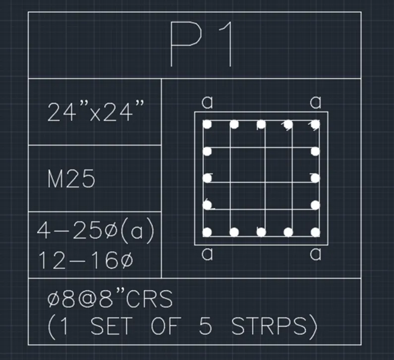
Using rectangle command, offset command, circle command and line command draw the column as given
STEP 4 :
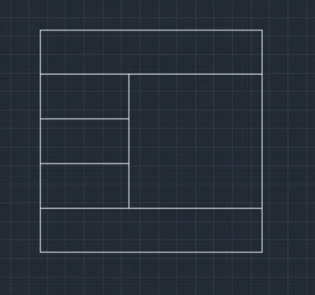
Using line command and draw the table as given in the figure
STEP 5 :
Copy the column drawing and place it in the table and using text command fill the details of P1 column in table
STEP 6 :
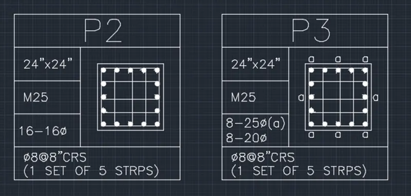
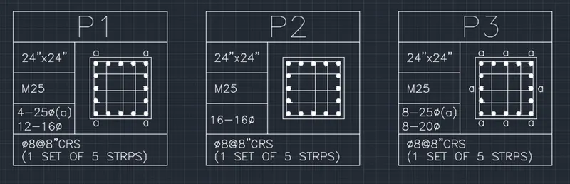
Make 2 copies of P1 as P2 and P3 and change the details as per the column P2 and P3
RESULT
The Given figure is drawn using necessary tools in AutoCAD
Q5
AIM : To draw the column detail as shown in figure
PROCEDURE
STEP 1 :
Type unit or UN in the command box and press enter
Set type of unit as architectural and precision as 0’-0(1/2)”
In Insertion scale set unit as inches
STEP 2 :
Type dimension style manager or D in the command box and press enter
Modify primary units as architectural and precision as 0’-0(1/2)”
STEP 3 :
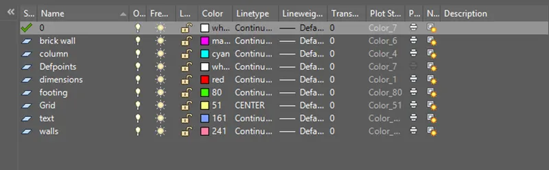
Type layer or LA in the command box and press enter
Create new layers according to drawing given
STEP 4 :
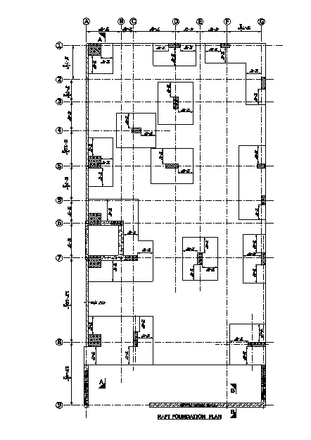
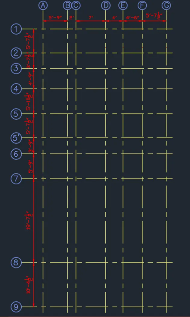
Using line command and draw the grid lines as given in the figure

STEP 5 :
Using Circle command, text command and dimensions command name the grid lines and distance between between the grids
STEP 6 :
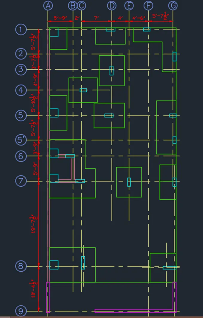
Using line command draw the column, foundation, concrete wall and brick wall as per the given figure
STEP 7 :
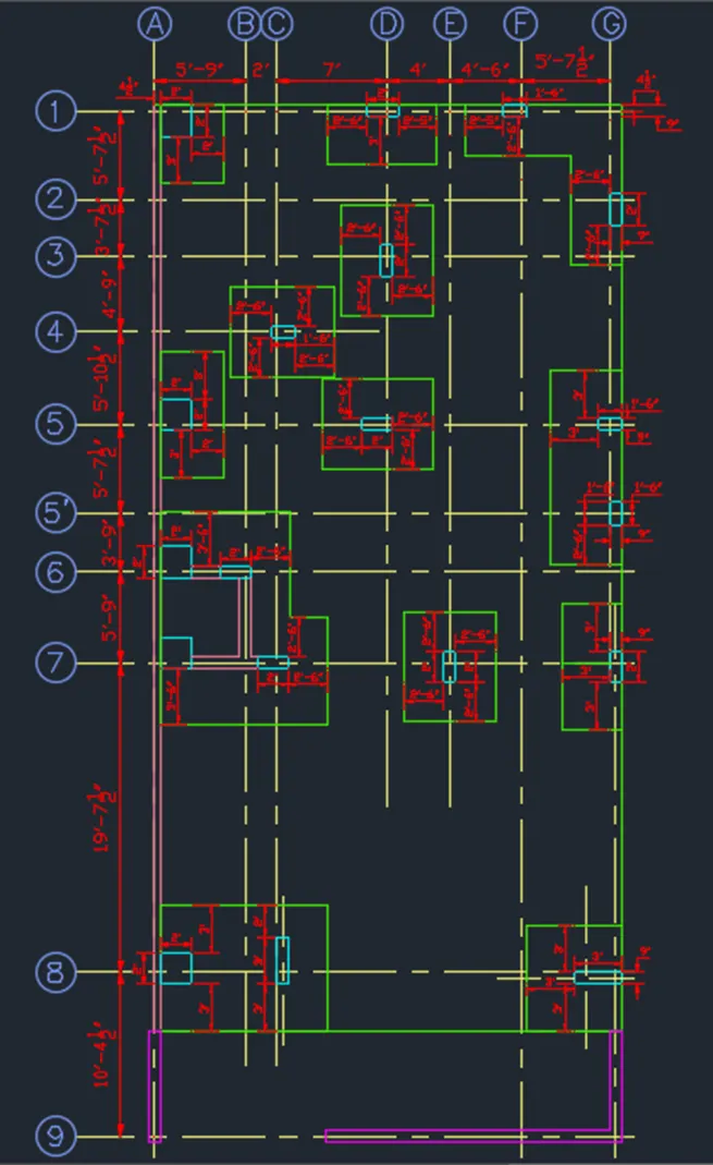
Using dimension command give the dimensions between the column and foundation.
STEP 7 :
Using hatch command and section line draw and text command 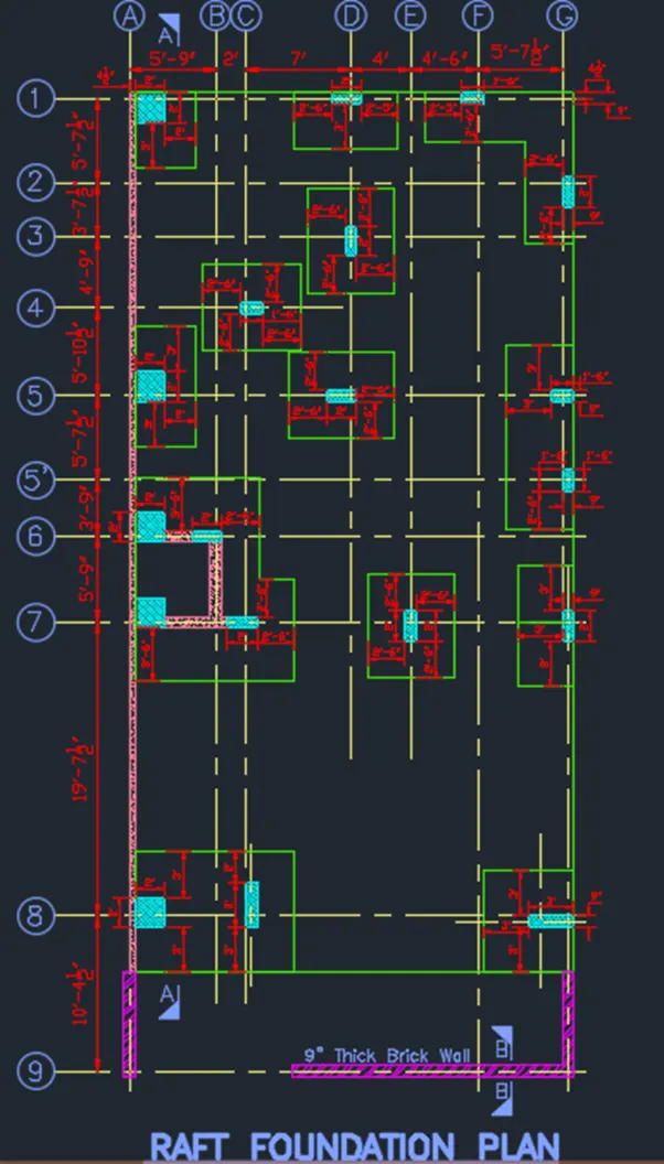
RESULT
The Given figure is drawn using necessary tools in AutoCAD