Creating a Wardrobe detailed drawing, Floor Plan, Kitchen Layout and Column Detail using AutoCad
Q1
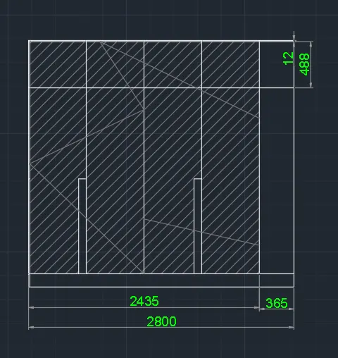
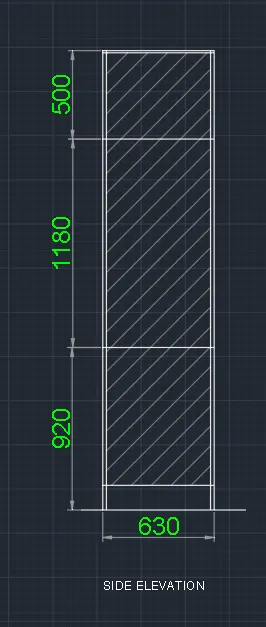
AIM:- to draw the elevation, cross-section, and side view of the wardrobe
- take a line command
- specify the first point and draw a baseline
- then by taking an offset command to specify the optimum offset distance and construct all other lines
- take a trim command and edit the drawing
- create a new layer as dimensions and change the properties as u wish
- then click on the dimension layer and select as the current layer
- take command as dim linear and mention the appropriate dimensions
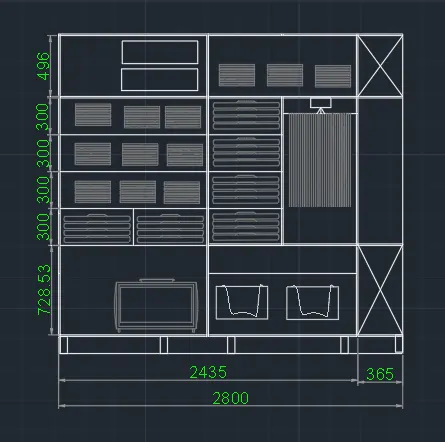
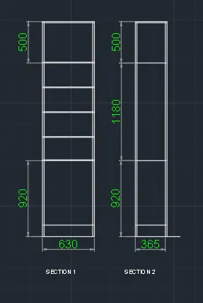
step 2:- to draw the cross-section of the wardrobe showing the compartments
- taking the line and offset command construct the crosssection of the wardrobe as per the given dimensions
- take a dim linear command and mention the dimensions
Q2
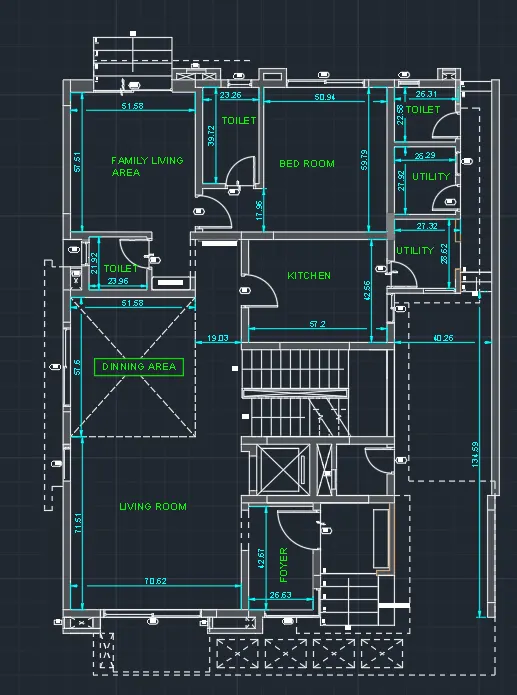
AIM:- to draw the floor plan and mention dimensions and text using layers
- take XLINE command
- draw a horizontal line
- specify the first point and draw a vertical line
- now by taking the offset command to construct the exterior and interior wall as per the given dimensions
- width of exterior wall: 230mm
- width of interior wall: 150mm
- using the commands offset and trim construct all other partitions and rooms
- construct a staircase by taking 10 steps for each flight
- width of the step
- tread: 300mm
- riser: 150mm
- then provide door openings for access into the rooms as per the given width of the door
- the openings for rooms and bathrooms are provided by windows and ventilators as per the given dimensions
- now create a layer for dimension style and text
- select the dimension layer as the current layer
- take dim linear command
- specify the point and mention the dimensions of the rooms
- select the text layer as the current layer
- specify the first point and write the text wherever required and represent the room names
Q3
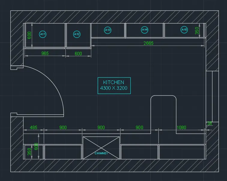
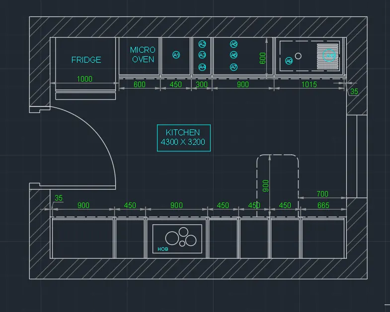
AIM:- to draw the kitchen layout and show dimensions and add text
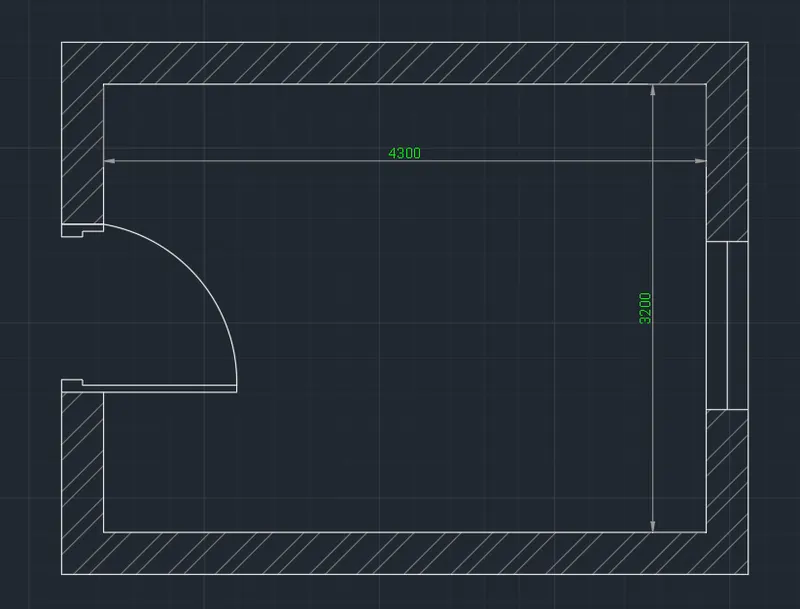
step 1:- to draw the outer wall and insert doors and windows
- take a rectangle command
- specify the first point
- specify the next point as 4300,3200
- Click enter and leave the command
- then take an offset command
- specify the offset distance as 300mm
- select the rectangle and take an offset on the outer side
- then insert the door and window at the required position
step 2:- to draw the layout of the kitchen platform and cupboards
- take an offset command
- specify the offset distance as required
- and draw the cupboards as shown
- specify the dimensions and text wherever required
Q4
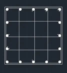
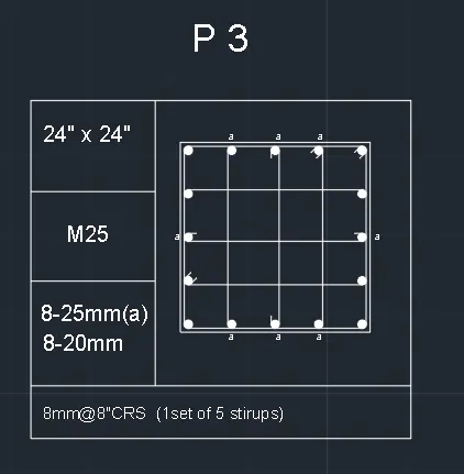
AIM:- to draw the cross-section of the columns showing main reinforcement and stirrup details
step 1:-
- take a rectangle command
- construct a rectangle of size 24" x 24"
- take an offset of 1" to represent the cover to the reinforcement
- show the details of the main reinforcement
- show the details of the stirrups and hook lengths at the end of the stirrups
step 2:-
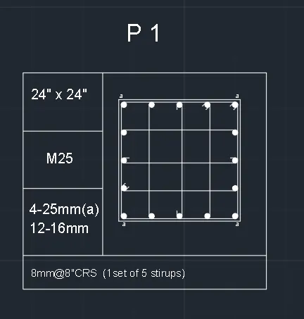
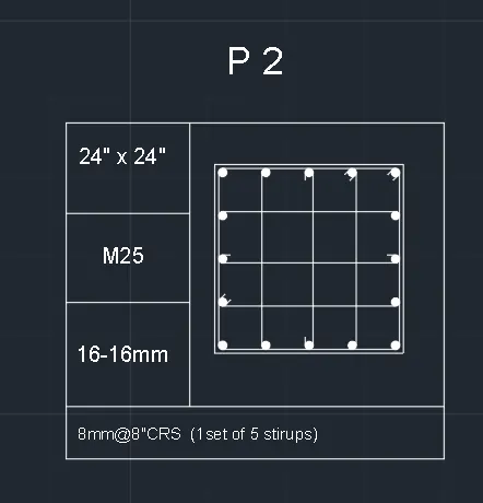
- mention the details of the main reinforcement (dia and number of the bars)
- format the details of the main reinforcement, shear reinforcement, grade of the concrete, size of the column in the tabular format for each of the columns as mention in the question
Q5
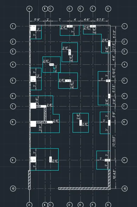
AIM:- to draw the footing details showing the position of the columns with reference to grids and the size of the footings.
- take the command XLINE
- specify the point and draw a horizontal and vertical line
- then create a grid line by taking offsets as mentioned in the drawing
- name the grids as u wish
- then taking the reference of the grids lines and grid numbers mark the position of the columns and the footings as per the mentioned dimensions
- hatch the columns
- represent the plinth beam of the lift pit
- show the dimensions wherever required.