Creating a Wardrobe detailed drawing, Floor Plan, Kitchen Layout and Column Detail using AutoCad
1)
Aim:
To draw the elevation and details of wardrobe.
Introduction:
A wardrobe is a standing closet used for storing clothes.
The earliest wardrobe was a chest, and it was not until some degree of luxury was attained in regal palaces and the castles of powerful nobles that separate accommodation was provided for the apparel of the great.
The name of wardrobe was then given to a room in which the wall-space was filled with closets and lockers, the drawer being a comparatively modern invention.
Commands used:
• Limits command
• Line command
• Offset command
• Hatch command
• Dimlinear command
• Dimstyle command
• Units command
Procedure:
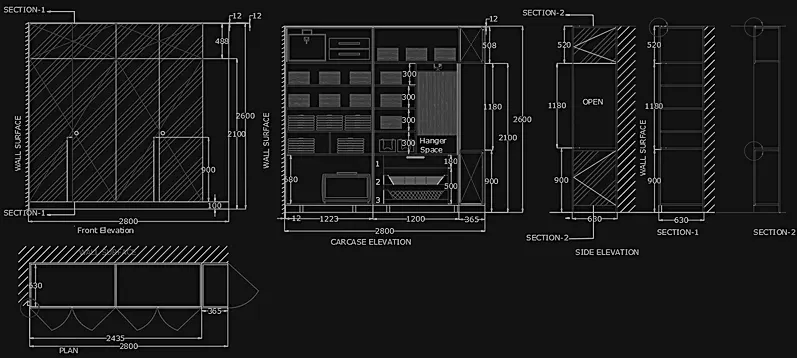
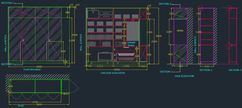
Front elevation:
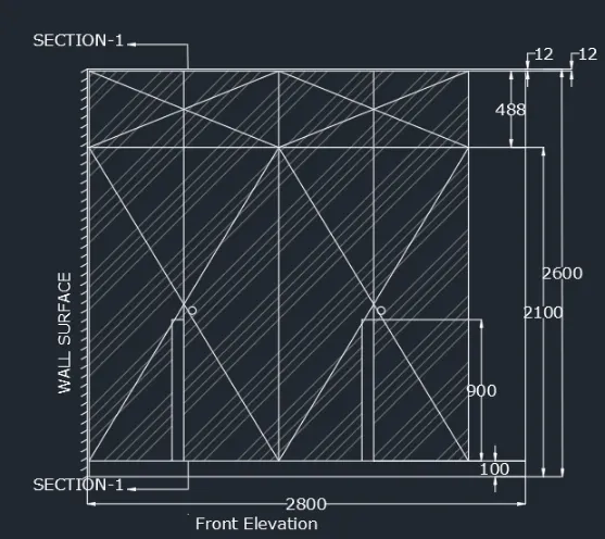
First we have to draw the line with line command of length 2800mm and draw a line again upwards with the length of 2600mm.
And next we have to draw the line backwards from the right corner of top with the length of 2800mm.
Then next join first line and the last line.
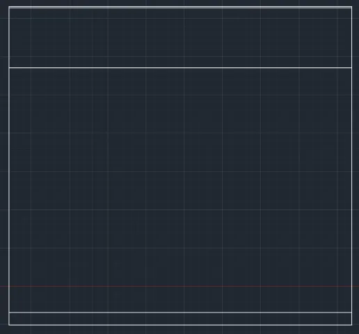
Next divide the vertically 5 times.
Next take the offset command and offset the horizontal line from the top with the length of 500mm.
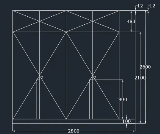
Again offset line to 12mm, and again offset the line from bottom of length 20mm.
Next draw the line crossly from 1st vertical line top to the third line bottom.
Do this step continuously when the figure completes the drawing.
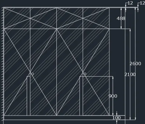
Sketching Carcase Elevation:
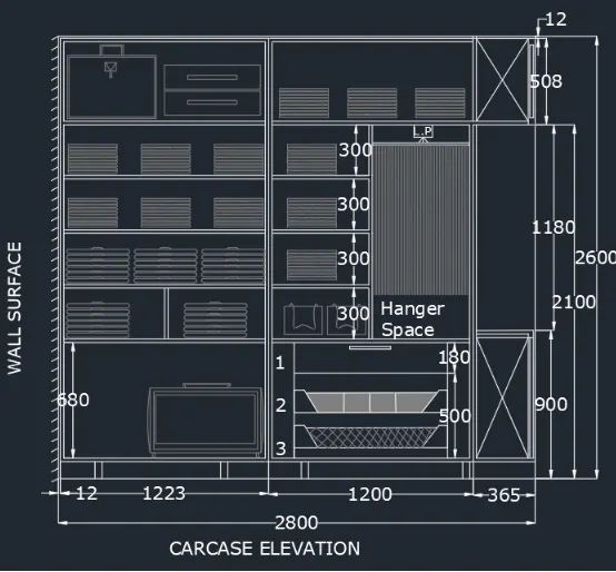
Project the lines to side from the elevation to bottom line.
Using OFFSET command, offset 100mm line, 2100 mm line from the bottom and 12mm thickness with ORTHO on.
Now project the ends of the cabinet from the plan view
Using OFFSET command, offset distance of 20mm (720-680=40; 40/2=20) from the bottom horizontal line from 100mm offsetted
line, set vertical line and top line from 12mm offsetted line.
Using OFFSET command, offset of 1223mm from the left end 12mm line is made. Now take offset of 20mm on both sides of this line using OFFSET command.
Using FILLET command, fillet the corners of the cabinet.
Using OFFSET command, offset line at a distance of 680mm from the bottom 20mm offsetted line, then again offset 20mm from that line, to create the inside partition.
Now create offset of 300mm and 20mm as thickness till it meets the height of 2100mm using OFFSET command
Now, Using DIVIDE command, diving the second portion of cabinet into half to create hanger space.
Using OFFSET command, offset distance as 580mm and the thickness of 20 mm is made.
Now trim off the unwanted line in the hanger space using TRIM command
Using DIVIDE command, divide the 1st shelf of 300mm from bottom left side in the middle of it
Using OFFSET command, offset 100mm from the two sides and bottom, to create drawers in right side.
Using OFFSET command, offset distance of 500mm from the bottom line is made
Using OFFSET command, draw a line from the bottom as offset of 900mm and 500 mm from the top, right side.
Now draw the legs of the cabinet by creating rectangle of 100*50mm using RECTANGLE command.
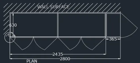
Using the RECTANGULAR command, draw a rectangle of size 2800*630mm
Using the OFFSET command, offset of 12mm inside is made to represent the thickness.
Explode the rectangle using the EXPLODE command.
Using OFFSET command, take offset from the right side of the rectangle for a distance of 365mm and also to two sides of 365mm by 12mm
Take offset of 365mm at a distance of 1217.5mm, i.e, at the mid of 2435mm, and now take the offset of 12mm to the left using OFFSET command.
Using LINE command, draw a clamp on the left side inside the wall of 20*20mm
Now, extend the bottom line to the left most line and trim the joints in the upper portion using TRIM command.
From 1217.5 mm, draw a line to the centre on both sides by OFFSET command, giving offset distance 608.75.( For sketching door)
Trim the Lines such that the line at the bottom portion only exist, now using OFFSET command, offset of 4mm is made on both sides and delete the centre line on both the door portion
Now using LINE command and ARC, draw the door.
Sketching of Side Elevation:
Project the height from the carcase elevation.
Using LINE command, draw a line on left side and Using OFFSET command offset 630mm from the right side.
Using OFFSET command, offset of 20mm is made to show the thickness on the top and the sides
Using OFFSET command, offsets from bottom as 100 mm, 900mm, 20mm thickness and 1180 mm are made.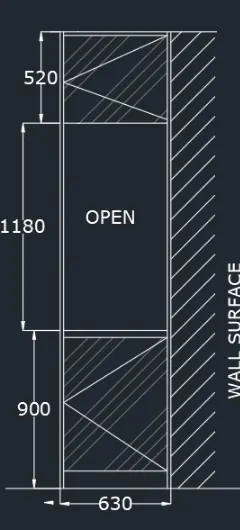
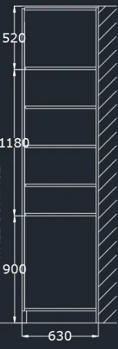
Sketching Section1-1:
Section 1-1 is in the elevation, so we need to project the height from the elevation
Using OFFSET command, offset of 630 mm, which is the width, is made.
Using OFFSET command, provide an offset of 20mm for thickness
For the inside cabinets, project lines from the carcase elevation of 100mm,900mm, 300mm and 20 mm as thickness
Now trim off the unwanted line using TRIM command.
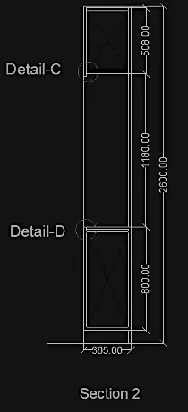
Sketching Section 2-2:
Project the height from the side elevation as the section is from the side elevation
Using OFFSET command, offse of 365mm is made as width
Using OFFSET command, offset on the sides and top of 20mm
Project the 900mm line from the bottom and 520mm line from the top
OUTPUT:
2)
Aim:
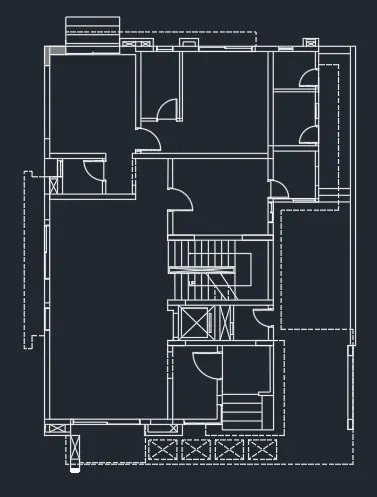
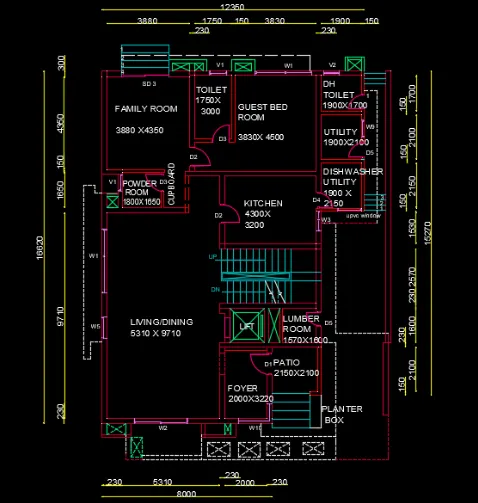
To draw the floor plan of the given building
Introduction:
A floor plan is a diagram that shows you the layout of an area from above.
Floor plans typically show the location of walls, windows, and doors, as well as installations such as furniture, cabinetry, and appliances.
Floor plans are usually drawn to scale and will indicate room types and room dimensions
Procedure:
• Using XLINE command, draw a horizontal and a vertical line
• Using OFFSET command, give an offset of 230mm from the vertical line to draw the wall thickness Sketching Family Room: Using OFFSET command, give an offset of 3880mm from the wall thickness and offset 230mm for the other sides. Using the OFFSET command, draw an offset of 300mm as wall thickness from the horizontal construction line. Draw another offset of 4350mm from the 300mm wall thickness for drawing the family room.
• Sketching Toilet: Using OFFSET command, give an offset of 1750mm from the right wall of family room, also offset of 150mm is made to show the wall thickness. Using the OFFSET command, draw an offset of 250mm from the horizontal construction line for the wall thickness of toilet on outside. Now draw an offset of 3000mm from the wall thickness, so that the toilet is sketched. From the offsetted lines, draw 150mm for the wall thickness inside.
• Sketching Guest Bed Room: Using OFFSET command, draw an offset from the wall of toilet at a distance of 3830mm. Also offset the wall thickness of 230mm. Now using OFFSET command, offset 4500 mm from the horizontal wall and also offset 230mm from that line
• Sketching DH toilet: Using OFFSET command, Take offset from the guest bed room wall of distance 1900mm towards the right side. Also offset the wall thickness 150mm from that line. Now offset a distance of 1700 from the horizontal line, wall thickness of 230mm. Also offset a wall thickness of 150mm. Now using TRIM command, trim off the unwanted lines of horizontal construction line
• Sketching of Utility room: Using OFFSET command, take an offset of 2100 mm downwards the wall of DH toilet. Also offset the wall thickness of 150mm
• Sketching of Dishwasher utility: From the Utility wall, take an offset of 2150mm downwards and also, wall thickness of 150mm.
• Sketching Kitchen: From the left wall of dishwasher utility room, take an offset of 4300mm to the left and wall thickness of 230mm. From the wall of the guest bed room, take an offset of 3200mm downwards and also wall thickness of 230mm. Now extend the topwall of Kitchen upto a distance of 1462mm excluding the wall thickness
• Sketching Cupboard and powder room: From the extended line, give a distance of 1000mm for the cupboard ans wall thickness of 150mm. Using OFFSET command, give an offset of 1800 mm from the wall and also the wall thickness of 230mm. Make the above wall of powder room as 150mm, Now using OFFSET command, take offset of 1650mm from that wall to the bottom. dish powder room 1800 cupboard utility kitchen 4300
• Sketching Living/Dining: Draw an offset of 9710mm from the wall of powder room and also 230mm for the wall thickness. Using TRIM command, trim off the rest of the vertical construction line
• Sketching Foyer: Using OFFSET command, draw offset from the wall of living room 2000mm to the right and wall thickness of 230mm. Draw the width of room 3220mm offsetting from the line extended from the living room. Now offset the wall thickness of 150mm. Again offset 230mm from the lift room and extend it to the right end.
• Sketching Patio: From the wall thickness of 230mm draw an offset of 2100mm downwards. From the wall of foyer draw an offset of 2150mm and a wall thickeness of 150 mm on the right side.
• Sketching lumber room: From the wall of patio, draw an offset of 1600mm towards backside. Offset a wall thickness of 230mm. To the left side, give an offset of 150mm, as wall thickness
• Sketching duct and lift: Using OFFSET command, draw an offset of 500mm from the 150mm wall of lumber room and wall thickness of 230mm. Now take an offset of 1620 mm from the wall for lift. Draw the side walls and front walls of 230mm.
• Sketching Stairs: Thread 300mm and rise 150mm. Divide the stair room and offset 200mm to two sides by the offset from the centre line. Now draw the first step, then offset 300mm upto 11 divisions, And the rest of the portion forms the landing, draw 10 threads from the landing on the other side of division. 300 2570 DN
• Sketching Outside ducts and steps: Create ducts at the front and backside. Steps on back with thread 350mm and side 250mm.
• Openings for Doors, Draw doors and windows: Openings are given by the TRIM command, where ever door is required. For D1=1000mm D2-900mm, D3-800mm, D4=750mm, D5-700 mm is trimmed accordingly. B
• By creating hinge and with CIRCLE command, circle with points with midpoints of hinges are drawn. Vertical line showing the shutter is shown and the rest of the circle is trimmed off.
• Create windows of sizes W1=2700mm,W2=2500mm, W3-900mm, W5=1000mm, W9800mm, V1=800mm, V2=750mm
• Now fillet the corners using FILLET command and Trim off the unwanted lines using TRIM command.
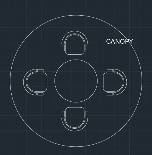
canopy circle:
In the menu bar click on circle > centre, radius specify the centre point as 10,10 and radius 452
In the meu bar click on circle > centre, radius specify the centre point same as the previous circle (10,10) and radius 1398
SEATS:
In the menu bar click on rectangular or in the command prompt type rec,specify the length of the rectangle as 662.3 specify the width of the rectangle as 298.0
In the command prompt type FILLET > RADIUS > 100.00 (to get curve edges in the comer)
In the menu bar> circle > 2-point ( 2 points are the end points of the top line)
In the men bar> circle > centre diameter centre is the midpoint of the line, diameter is 719.0
In the menu bar> circle > centre, diameter centre is the midpoint of the line diameter is 777.2 now, extend the centre line and trim the extra's In the menu bar click fillet blend curves > and select the arc
In the menu bar click fillet blend curves > and select the arc In the menu bar click fillet blend curves > and select the arc
OUTPUT:
3)
Aim:
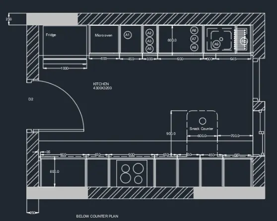
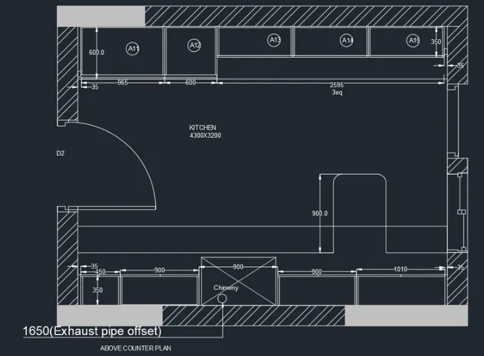
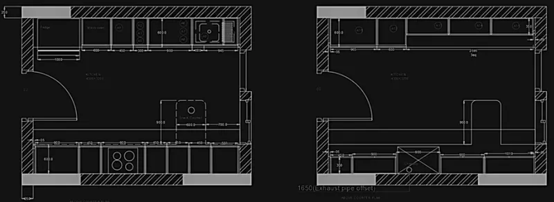
To Create the Kitchen Layout as shown in the Figure
Introduction:
The kitchen layout is the shape that is made by the arrangement of the countertop, major appliances and Storage areas.
This floor plan creates the kitchen's work triangle – the path that you make when moving from the refrigerator to the sink, to the range to prepare a meal.
Procedure:
• Below Counter plan:
i. Sketching the wall:
Draw a rectangle of 4300 and 3200mm using RECTANGLE tool.
Draw an offset of 230mm as wall thickness towards outside using OFFSET command.
ii. Sketching Left cabinet and fridge:
Fridge is drawn on leftmost side by RECTANGULAR command, Take an offset of 1000mm and start drawing slab showing the cabinet below.
Now using OFFSET command, offset 600mm for cabinet below for microwave oven, give an offset of 20mm to show the partition of cabinet below.
For width of cabinet, give 600mm offset, give 20mm inside offset and 10mm offset for thickness.
From 600mm offset of microwave cabinet, give an offset of 450mm for A1.
From that give 300mm offset A2,A3, A4. Now from 300 mm offset give another offset of 900mm for A5, A6, A7.
Now draw 35mm offset from the right side for the hinge and give thickness of 20mm.
From the 35mm draw an offset of 300mm towards left for the cabinet sink drain and rest will be cabinet below the sink, Assuming 300mm from the right.
For all the divisions of cabinet, take 20mm on both side to show the thickness.
To create doors, extend the line of all the divisions and give 10mm offset on both sides in the 10mm offset given for the thickness. Now erase the extended lines and trim the horizontal line for opening of doors.
iii. Sketching Right cabinets and hob:
Using OFFSET command, 35mm offset is made from the left and create a hinge.
For width of cabinet, give 600mm offset, give 20mm inside offset and 10mm offset for thickness.
From 35mm give 900 mm offset. Give an offset of 450mm from 900mm offset.
Again offset a distance of 900mm. Offset a distance of 450mm three times from the respective precedding offset.
From the right side 35mm for hinge and rest distance will be 630mm which shows the top of cabinet. Offset a distance of 20mm on both sides of all offseted lines.
To create doors, extend the line of all the divisions and give 10mm offset on both sides in the 10mm offset given for thickness.Erase the extended line and trim the horizontal line for opening of doors.
Extend the centre line to the thickness for 3 cabinet from the left. Hob is drawn by rectangle and circle tool in the plan of third cabinet from the left
iv. Sketching snack counter:
Using OFFSET command, pffset a distance of 700mm from the left side of the wall and 900mm from the 600mm width of cabinet. Fillet the end of the snack counter with fillet radius 10mm.
• Above counter plan:
Copy the wall of the below counter plan as the dimensions are same.
i. Sketching Right side counter:
Draw a line of width 350mm from the wall, to inside offset 20mm to show the thickness.
Offset a distance of 35mm from the left side of wall.
Now offset 450mm for the top of the cabinet. Offset 900mm for 3 times for the next cabinets.
From the right side offset 35mm, the rest distance of 1095mm will be the cabinet.
For the second 900mm offset, draw a rectangle and from a distance of 1650mm from the left side of wall, draw a circle for the chimney.
For the rest of the offset, offset 20mm on both sides for the thickness.
From the plan, the below counter and snack counter will be also see, sketch that and show it in light colour as same distance as in the below counter plan.
ii. Sketching Left side counter.
From the left side wall take 35mm offset to draw the hinge.
Draw 600mm offset as width from the horizontal wall. Draw 10mm offset to show the door.
Now usinf OFFSET command, draw an offset of 38mm from the 10mm door for the cabinet.
From 35mm hinge, offset 965mm to the right A11. From that offset 600mm for the next cabinet A12.
Take offset of 350mm from the horizontal wall as width of next cabinets.
Offset a distance of 35mm from the right. The rest distance is 2665mm which is divided into 3 equal parts, A13, A14 A15.
Now offset 20mm on both sides of divisions and also 20mm in front for doors.
Now offset 10mm in backside for showing the thickness.
iii. Sketching Doors, sliding doors and windows:
Create door in the left wall of the kitchen on both the plan.
Consider door of 900mm width, trim 900mm from the wall thickness.
Draw a hinge of 20mm and draw circle from center of one hinge to another.
Now draw a vertical line from one hinge to circle to show the opening.
Now trim off the rest of circle.
To sketch the window, consider a window of width 900mm.
From the 600mm width of cabinet, take an offset of 900mm, draw the hinges and shutters of windows using LINE command.
Copy it to the above cunter plan. To sketch sliding doors, take 200mm offset from the window. Give an opening of 900mm,take offset of 900mm from the 200mm offset.
Sketch the shutters of the sliding doors. Copy it in the other plan too.
4)
Aim:
To sketch the column details as given in the figure.
Procedure:
Open AutoCad and set it to imperial
Set the units to feet and inches and limits
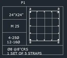
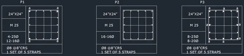
•Sketching P1 (A column of size 24"*24" having 4 bars of 25mm dia and 12 bars of 16mm diameter and connected by 8mm diameter stirrups)
Using RECTANGLE command, draw a rectangle of dimension 24"*24"
Offset of 0.5" is made to show the column outline.
Explode the inner rectangle so that the lines can be selected separately.
Draw circle with tan-tan radius selection with the tangent as the two sides of the column and 0.5" radius. As the four corners are having 25mm diameter bars, mirror the circles and draw horizontal and vertical planes.
Using DIVIDE command, divide the leftmost line of the column with 4 segments
Now create a circle with the centre radius method with radius 0.31" and place the side of the circle with centre of point. vii. Copy the two circle and place it in the position of the points.
Mirror the 16mm diamter bars by drawing vertical mirror plane and delete the points created.
Again divide the horizontal lines into 4 segments and copy the circle and plcae the side of circle in the centre of the point.
Connect the bars by 8mm stirrups for that drawn line with LINE command connecting 16mm diameter bars
Now draw the rings by arc-3 point method and mirror it.
Fillet the corners of the column outline with fillet radius 0.5"
Use DONOUT command, to fill the circle
Using DO command, specify the inner diameter as O and outer diameter as 0.1" for 4 corner reinforcement and 0.62" for inside reinforcement and specify the centre of the donout to get it filled.
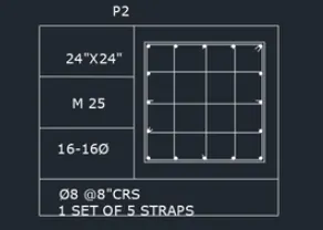
•Sketching P2 (A column of size 24"*24" having 16 bars of 16mm diameter connected by 8mm diameter stirrups)
Using RECTANGLE command, create a rectangle with dimension 24"*24"
Offset 0.5" to show the column outline.
Explode the inner rectangle so that the lines can be selected separately.
Draw circle with tan-tan radius selection with the tangent as the two sides of the column and 0.31" radius.
Using DIVIDE command, divide the leftmost line of the column with 4 segments
Now create a circle with the centre radius method with radius 0.31" and place the side of the circle with centre of point.
Copy the two circle and place it in the position of the points.
Mirror the 16mm diamter bars by drawing vertical mirror plane and delete the points created.
Again divide the horizontal lines into 4 segments and copy the circle and plcae the side of circle in the centre of the point.
Connect the bars by 8mm stirrups for that drawn line with LINE command connecting 16mm diameter bars
Now draw the rings by arc-3 point method and mirror it. xii. Fillet the corners of the column outline with fillet radius 0.31"
Use DONOUT command, to fill the circle xiv. Using DO command, specify the inner diameter as O and outer diameter as 0.31" for 4 corner reinforcement and specify the centre of the donout to get it filled.
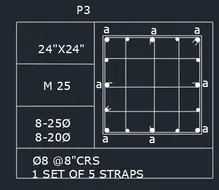
•Sketching P3 (A column of size 24"*24" having 8 bars of 25mm diameter and 8 bars of 20mm diameter and connected by 8mm diameter stirrups)
Using RECTANGLE command, draw a rectangle of dimension 24"*24"
Offset of 0.5" is made to show the column outline.
Explode the inner rectangle so that the lines can be selected separately.
Draw circle with tan-tan radius selection with the tangent as the two sides of the column and 0.5" radius. As the four corners are having25mm diameter bars, mirror the circles and draw horizontal and vertical planes.
Using DIVIDE command, divide the leftmost line of the column with 4 segments
Now create a circle with the centre radius method with radius 0.39" and place the side of the circle with centre of point.
Copy the two circle and place it in the position of the points.
Mirror the 20 mm diamter bars by drawing vertical mirror plane and delete the points created.
Again divide the horizontal lines into 4 segments and copy the circle and plcae the side of circle in the centre of the point.
Connect the bars by 8mm stirrups for that drawn line with LINE command
Now draw the rings by arc-3 point method and mirror it.
Fillet the corners of the column outline with fillet radius 0.5"
Use DONOUT command, to fill the circle
Using Do command, specify the inner diameter as O and outer diameter as 0.1" for 4 corner reinforcement and 0.78" for the 8 reinforcement and specify the center of the donout to get it filled.
OUTPUT:
5)
Aim:
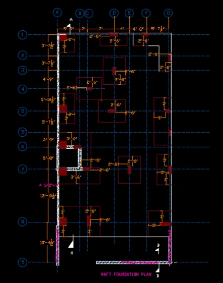
To sketch the Raft layout as shown in figure
Introduction:
A raft is any flat structure for support or transportation over water.
It is usually of basic design, characterized by the absence of a hull.
Procedure:
• Open AutoCad and set imperial units, change the units as architecture
• Sketching Grid lines:
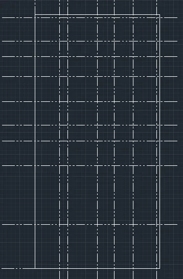
Draw a vertical line with the construction line command, XL-V
Using OFFSET command, offset the vertical line by a distance of 5'9", 2', 7, 4, 4'6", 5' 7 1/2"
Now draw a horizontal line with construction line command XL-H
Using OFFSET command, offset the horizontal line by a distance of 57 1/2", 37 1/2" 4'9" 5' 101/2" 5'71/2"39" 5'9", 13.10' 1/2", 10'41/2"
Change the line type of these lines as ISO dash by clicking on line type and selecting load from the dialogue box and make ISO dash current linetype.
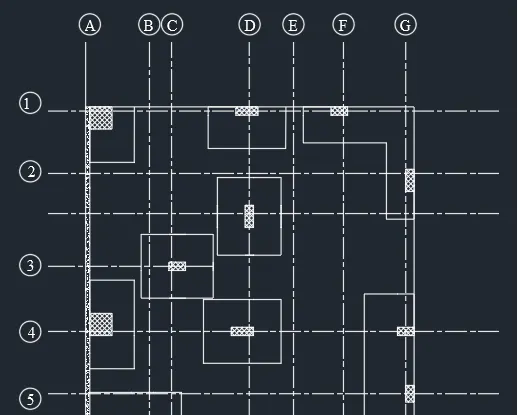
Mark the horizontal lines from 1 to 9 and vertical lines from A to G.
Draw the bottom thickness of wall as 9" with the grid line at the centre.
A thickness of 41/2" is drawn from the grid line inside the left vertical grid line.
• Sketching Column between grid line A & B and 1 & 2
i. From the 41/2" thickness line, draw a rectangle of 24"*24", using RECTANGLE command, giving the base point ii. Explode the rectangle
iii. From the column, offset 2' vertically and 3' horizontally.
iv. By fillet tool, with fillet radius o join the lines drawn to make the mat.
v. Hatch the column and selecting ANS 137 and scale 20
• Sketching Column between grid line C & E and 1 & 2
From the grid point D, draw an offset of 9' 1/2"
Create a rectangle by selecting the base point as 9'1/2" line and giving dimensions as 2" and 9"
Now delete the 9'1/2"line
Explode the rectangle and offset, with a distance of 2'6" vertical line on both sides and 3' horizontal line.
Fillet both the corners with fillet radius as O vi. Hatch the column and selecting ANS 137 and scale 20
• Sketching Column between grid line E & G and 1&2 and F & G and 2 & 3
From the grid point D, draw an offset of 4'1/2"
Create a rectangle by selecting the base point as 9'1/2" line and giving dimensions as 18" and 9"
Now delete the 4'1/2" line
Explode the rectangle and give offset with adistance of 2'6" vertical lines on left side and 2'6" horizontal line
Fillet both the corners with fillet radius as o
Hatch the column and selecting ANS 137 and scale 20
For the next colum, offsetof 4'1/2" is made upwards the grid line 2
Create rectangle by selecting the 4'1/2" line as base point and dimension 9"*24" Explode the rectangle
Offset 2'6" horizontally and vertically from the columns.
Fillet both the corners with fillet radius as o xii. Hatch the column and selecting ANS 137 and scale 20
• Sketching Column between grid line C & E and 2 & 4
From the grid point 2, draw an offset of 2.10'1/2"
From grid point D, offset a distance of 4' 1/2"
Create a rectangle by selecting base point as intersection of two offsetted lines and giving dimensions as 9" and 24"
TRIM the offsetted line
Explode the rectangle and give offset with a distance of 2'6" on all the sides
Fillet both the corners with fillet radius as o
Hatch the column and selecting ANS 137 and scale 20
• Sketching Column between grid line A&D and 1 & 5
From the grid point 4, draw an offset of 4'1/2"
From grid point A, offset a distance of 7' 1/2"
Create a rectangle by selecting base point as intersection of two offsetted lines and giving dimensions as 9" and 18"
TRIM the offsetted line
Explode the rectangle and give offset with a distance of 2'6" on all the sides
Fillet both the corners with fillet radius as o vii. Hatch the column and selecting ANS 137 and scale 20
• Sketching Column between grid line A & B and 4 & 5
From the grid point 5, draw an offset of 4'1/2"
Create a rectangle by selecting base point as intersection of 4'1/2" and giving dimensions as 24" and 24"
Delete the offsetted line
Explode the rectangle and give offset with a distance of 3' on left and right sides and 2' towards front
Fillet both the corners with fillet radius as o
Hatch the column and selecting ANS 137 and scale 20
• Sketching Column between grid line C & E and 4 & 5
From the grid point 5, draw an offset of 4'1/2" upwards
From grid point D, offset a distance of 41/2"
Create a rectangle by selecting base point as intersection of 4'1/2" from the grid point 5 and grid line D and giving dimensions as 9" and 24"
Delete the offsetted line
Explode the rectangle and give offset with a distance of 2'6" on all the sides
Fillet both the corners with fillet radius as O
Hatch the column and selecting ANS 137 and scale 20
• Sketching Column between grid line F & G and 4 & 6
From the grid point 5, draw an offset of 4'1/2"
Create a rectangle by selecting base point as intersection of 4'1/2" and the wall and giving dimensions as 9" and 18"
Delete the offsetted line
Explode the rectangle and give offset with a distance of 3' on one side and 3' towards the front
Fillet both the corners with fillet radius as o
Hatch the column and selecting ANS 137 and scale 20
From the grid point 5, draw an offset of 9"
Create a rectangle by selecting base point as intersection of 9" from the wall and giving dimensions as 9" and 18"
Delete the offsetted line
Explode the rectangle and give offset with a distance of 3' on one side and 3' towards the front
Fillet both the corners with fillet radius as o
Hatch the column and selecting ANS 137 and scale 20
• Sketching Column between grid line F & G and 6 & 8
From the grid point 7. draw an offset of 10'1/2"
Create a rectangle by selecting base point as intersection of 10'1/2" and the wall and grid line D and giving dimensions as 9" and 2
Delete the offsetted line
Explode the rectangle and give offset with a distance of 3' on left and 3' on right side and 3' towards front
Fillet both the corners with fillet radius as O
Hatch the column and selecting ANS 137 and scale 20
• Sketching Column between grid line D&F and 6 & 8
From the grid point 7 draw an offset of 10'1/2"
From grid point E, offset a distance of 4' 1/2"
Create a rectangle by selecting base point as intersection of two offsetted lines and giving dimensions as 24" and 9"
Delete the offsetted line
Explode the rectangle and give offset with a distance of 2'6" on all the sides
Fillet both the corners with fillet radius as O
Hatch the column and selecting ANS 137 and scale 20
• Sketching Column between grid line A & D and 5 & 8
From the grid point 6, draw an offset of 4'1/2"
Create a rectangle by selecting base point as intersection of 4'1/2" and wall and giving dimensions as 24" and 24"
Delete the offsetted line
Draw a 9" thickness wall from the column at a distance of 3'9"
From the corner, draw another colum by rectangle 9"*2'
Draw the wall downwards at a distance of 5'8 -1/4" and rightwards 24-1/2"
Draw another column of 9"*2' on the rightmost side
Mirror the 24"* 24" column on the other side, with mirror line the midpoint between grid 6 and 7
Give offset with a distance of 2'6" to the front from the wall and column
Give offset distance 3' to the right and left side
Hatch the wall by AR CONC of scale 1 and selecting ANS 137 and scale 20
• Sketching Column between grid line A&D and 5 & 8
From the grid point 8, draw an offset of 9" downwards
Create a rectangle by selecting base point as intersection of 9" and wall and giving dimensions as 24 and 24"
Delete the offsetted line
Explode the rectangle and extend the base of rectangle and from grid point C. offset 4'1/2" and create a rectangle of 9*2'6"
Give offset with a distance of 2'6" to the front and left of the 9"*26" and offset of 3' from the 2*2' rectangle
Hatch the column and selecting ANS 137 and scale 20
• Sketching Column between grid line A & D and 5 & 8
From the grid point 8, draw an offset of 4'1/2 downwards
Create a rectangle by selecting base point as intersection of 4'1/2" and wall and giving dimensions as 3' and 9"
Delete the offsetted line
Give offset with a distance of 3
Hatch the column and selecting ANS 137 and scale 20
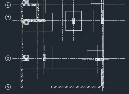
OUTPUT: