Creating a Wardrobe detailed drawing, Floor Plan, Kitchen Layout and Column Detail using AutoCad
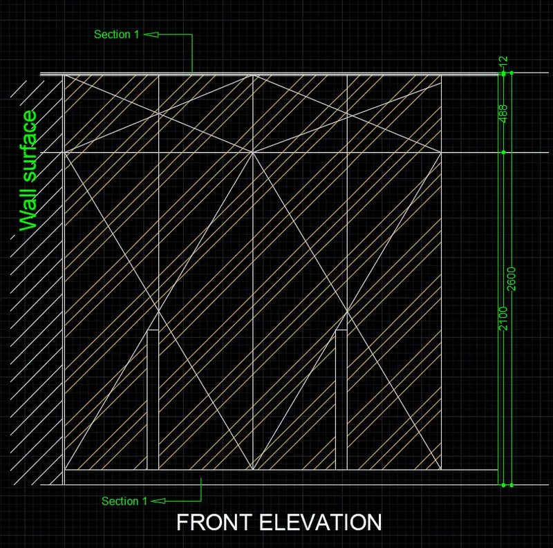
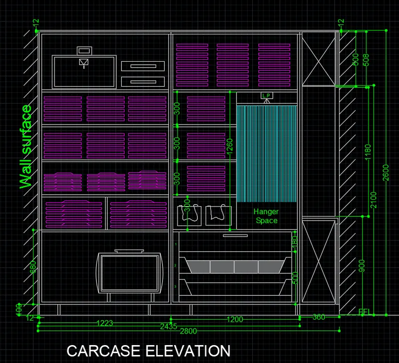
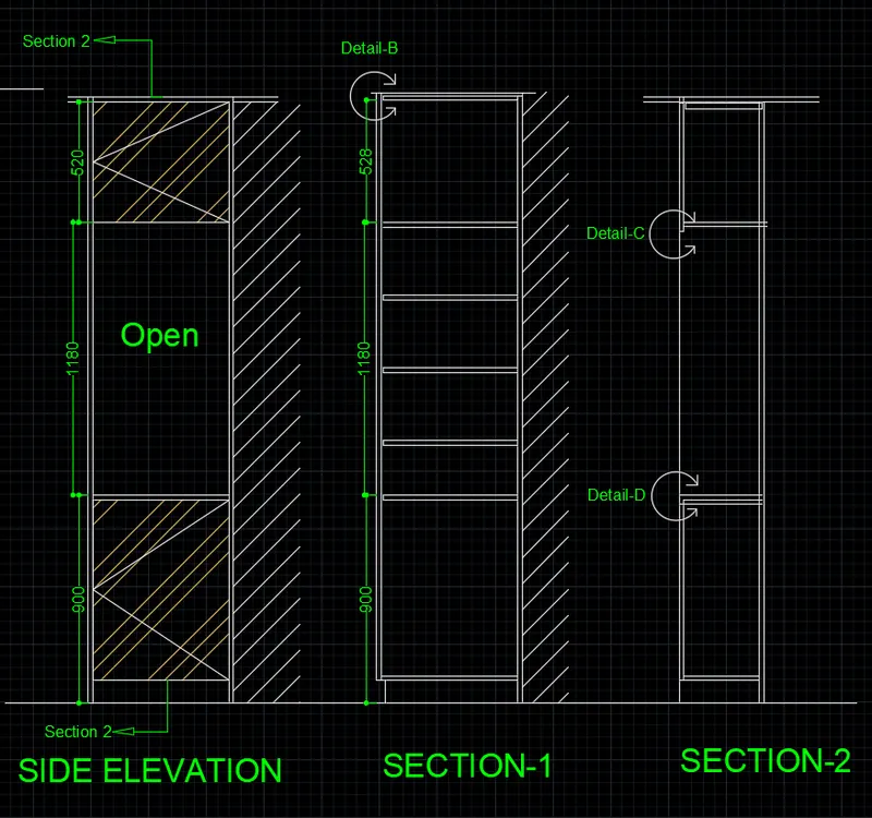
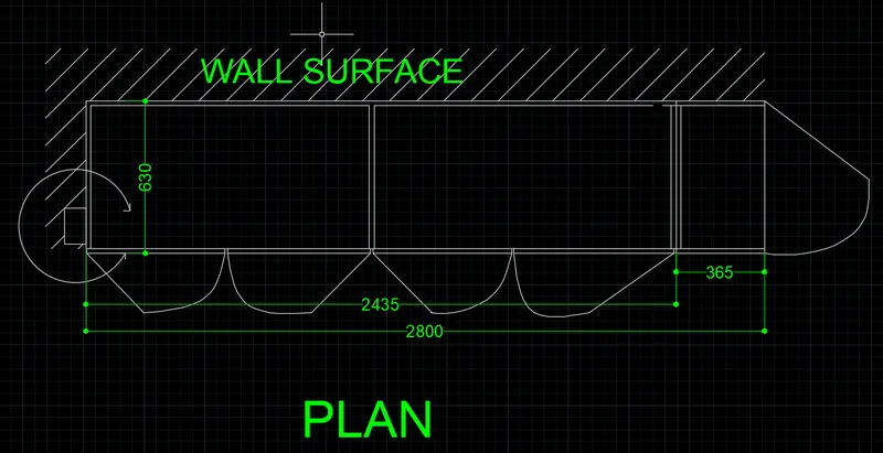
1. Draw the elevation and details of a wardrobe as shown in the Figure below. After sketching, you need to provide the dimensions and text with the use of layers. Use proper text styles and dimension methods to document it. Also, assume dimensions, wherever needed.
Note: All dimensions are in mm.
AIM:
To Draw the Elevation and details of a Wardrobe as shown in the figure.
REQUIRED TOOLS:
SCALE
LAYER
LINE
RECTANGLE
OFFSET
TEXT
DIMENSION
CIRCLE
FILLET
M TEXT
TRIM
MULTILEADER
HATCH
PROCEDURE:
STEP-1
IMPORTING PDF FILES INTO DRAWING:
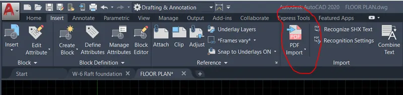
Importing the pdf file into the current drawing for a better understanding of the dimensions of the given drawing file.
INVOKING THE TOOL:
INSERT > PDF IMPORT > SELECT RESPECTED DOWNLOADED DRW. FILE >
STEP-2
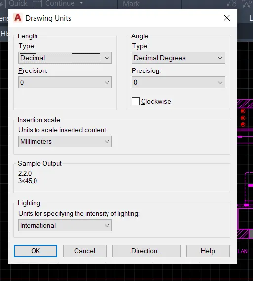
SETTING OUT UNITS:
COMMAND: UN>
UNITS: Decimal
PRECISION: 0
INSERTION SCALE: MM
STEP-3
SCALING:
COMMAND: SC>
Select the object: select by window crossing method >
specify base point: select the base point of the object
specify scale factor or [copy/Reference]: select Reference
specify reference length:
Specify new length or (points): >
STEP-4
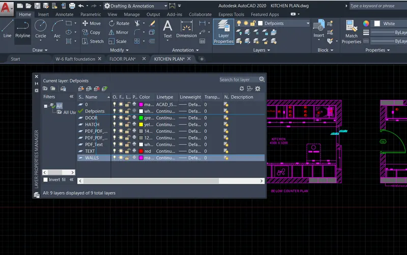
CREATING LAYERS:
INVOKING THE TOOL:
RIBBON: HOME > LAYER PROPERTIES > NEW LAYER > COLOR > LINETYPE > LINEWEIGHT>
STEP-5
Sketching the drawing as per the given reference drawing and dimensions by using the different commands like
LINE, RECTANGLE, OFFSET, TRIM, CIRCLE, ETC.,
STEP-6
DIMENSIONS:
Given the dimensions as required places, by using different dimensioning types.
Linear Dimensioning
COMMAND: DIMLIN>
Continue dimensioning
COMMAND: DIMCON>
STEP-7
TEXT:
written the text as given in reference drawing by using
MTEXT:
COMMAND: MT>
TEXT:
COMMAND: DT>
STEP-8
MULTILEADER:
INVOKING THE TOOL:
RIBBON: ANNOTATE> LEADERS > MULTILEADER
COMMAND: MLEADER>
For creating the annotation of the sections.
STEP-9
HATCH:
INVOKING THE TOOL:
COMMAND: HATCH >
Select the required patterns and color >
pick an internal point or [select object]:
RESULT:
Sketched the drawing by using various Tools.
Q2. Draw the floor plan as shown in the Figure. Use the proper drafting tools to sketch the plan. Do not hatch or draw the furniture. You need to draw the floor plan with the following:
Note: You can also import the Floor_Plan.pdf into your current drawing and start working on the project. You need to scale the imported pdf file using reference option. All dimensions are in mm.
- Walls (Exterior and Interior)
Wall Thickness: Exterior Wall- 230mm, Interior Wall: 150 mm (Wherever Required)
- Doors and Windows: Assume the size of the doors and window.
2.1 Stairs: Tread-300mm, Riser-150mm
- Insert Text wherever required
- Insert the dimensions using proper dimension techniques
AIM:
To draw the floor plan as shown in the figure.
REQUIRED TOOLS:
SCALE
LAYER
XLINE
LINE
RECTANGLE
OFFSET
TEXT
TRIM
FILLET
DIMENSION
CIRCLE
MOVE
COPY
ARC
M TEXT
MULTILEADER
PROCEDURE:
STEP-1
IMPORTING PDF FILES INTO DRAWING:
Importing the pdf file into the current drawing for a better understanding of the dimensions of the given drawing file.
INVOKING THE TOOL:
INSERT > PDF IMPORT > SELECT RESPECTED DOWNLOADED DRW. FILE >
STEP-2
SETTING OUT UNITS:
COMMAND: UN>
UNITS: Decimal
PRECISION: 0
INSERTION SCALE: MM
STEP-3
SCALING:
COMMAND: SC>
Select the object: select by window crossing method >
specify base point: select the base point of the object
specify scale factor or [copy/Reference]: select Reference
specify reference length:
Specify new length or (points): >
STEP-4
XLINE:
COMMAND: L>
Specify a point: Horizontal
specify a point: Vertical
OFFSET
COMMAND: OFF>
External walls 230mm
Internal walls 150mm
Vertical lines are offset as per the given room dimensions along with the thickness of the walls.
Horizontal lines are also offset as per room dimensions.
TRIM:
COMMAND: TR>>
By using the trim command all extended lines and extra lines are trimmed.
LINE:
COMMAND: L>
Line command is used for creating the doors and windows, as the clear distance of openings.
DOTTED LINES:
Creating one dotted line layer and loaded the ACAD_ISO 03W100 line type.
Draw the dotted lines as where it is required.
TEXT:
COMMAND: MTEXT
Texting the respected room name along with dimensions.
Justification- Middle Center, Top left corner
DIMENSIONS:
COMMAND: DIMLIN:
Plot the dimensions as room-wise and Break the dimension line by Break option in Dimensions.
RESULT:
Sketching Floor plan Drawing by using various tools, and given the dimensions to all rooms.
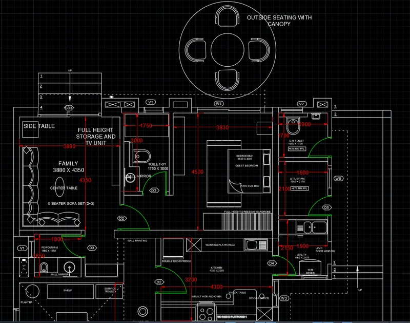
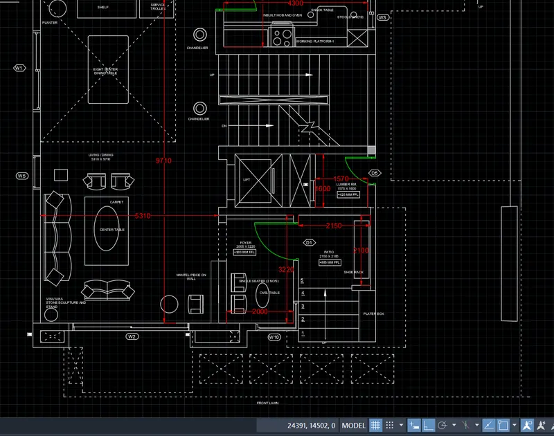
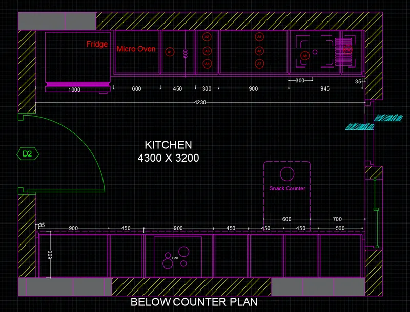
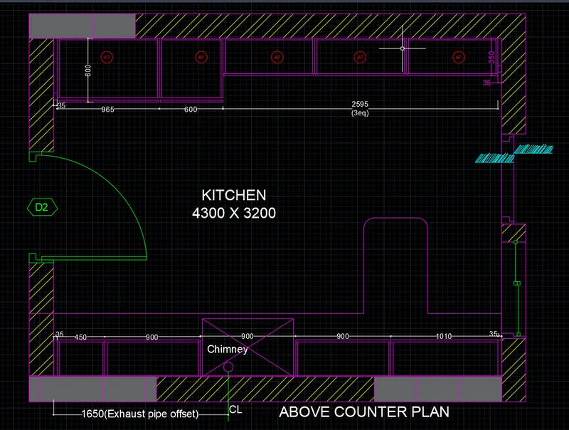
Q3. Create the Kitchen Layout as shown in the Figure below. Also, use proper dimension techniques to dimension the kitchen layout. Also, insert text wherever required. All dimensions are in mm.
AIM:
To draw the Kitchen Layout as shown in the figure.
REQUIRED TOOLS:
SCALE
LAYER
XLINE
LINE
RECTANGLE
OFFSET
TEXT
TRIM
FILLET
DIMENSION
CIRCLE
ARC
MOVE
COPY
M TEXT
MULTILEADER
PROCEDURE:
STEP-1
IMPORTING PDF FILES INTO DRAWING:
Importing the pdf file into the current drawing.
INVOKING THE TOOL:
INSERT > PDF IMPORT > SELECT RESPECTED DOWNLOADED DRW. FILE >
STEP-2
SETTING OUT UNITS:
COMMAND: UN>
UNITS: Decimal
PRECISION: 0
INSERTION SCALE: mm
STEP-3
SCALING:
COMMAND: SC>
Select the object: select by window crossing method >
specify base point: select the base point of the object
specify scale factor or [copy/Reference]: select Reference
specify reference length:
Specify new length or (points): >
XLINE:
COMMAND: XL>
Specify first point: select the point
Specify next point: Create a horizontal line
specify next point create one vertical line
OFFSET
COMMAND: OFF>
External walls 230mm
Internal walls 150mm
Vertical lines are offset as per the given room dimensions along with the thickness of the walls.
Horizontal lines are also offset as per room dimensions.
TRIM:
COMMAND: TR>>
By using the trim command all extended lines and extra lines are trimmed.
TEXT:
COMMAND: MTEXT
Texting the respected room name along with dimensions.
Justification- Middle Center, Top left corner
DIMENSIONS:
SETTING THE DIMENSIONS:
Dimension Style manager: DST>/D>
Symbols and Arrow > Arrowhead > Dot>
Primary Units> Decimal > precision:0 >
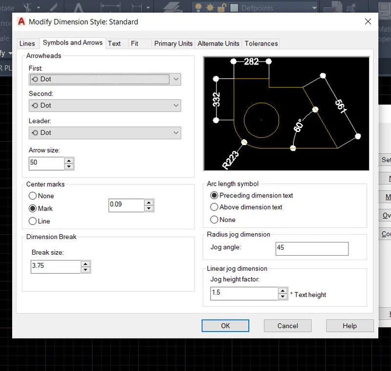
After setting the dimensions
COMMAND: DIMLIN> for dimensioning the linear type lines
COMMAND: DIMCON> continue dimension in the line.
HATCH:
COMMAND: H>
Select the required patterns > ANSI32
Scale the Hatch pattern: based on drawing scale requirement
pick an internal point or [select object]:
RESULT:
Sketch out the given drawing by using the various tools.
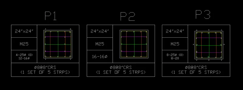
4. Sketch the column details as shown in Figure. Insert dimensions and text in the figure. Refer to the bar sizes from the schedule.
8mm ---- 0.31 Inches
25mm--- 1 inch
16mm—0.62 inches
AIM:
To Sketch the column details as shown in the figure.
REQUIRED TOOLS:
TABLE
RECTANGLE
CIRCLE
LINE
OFFSET
TRIM
MTEXT
MOVE
COPY
PROCEDURE:
Step-1
Setout the Units:
COMMAND: UN>
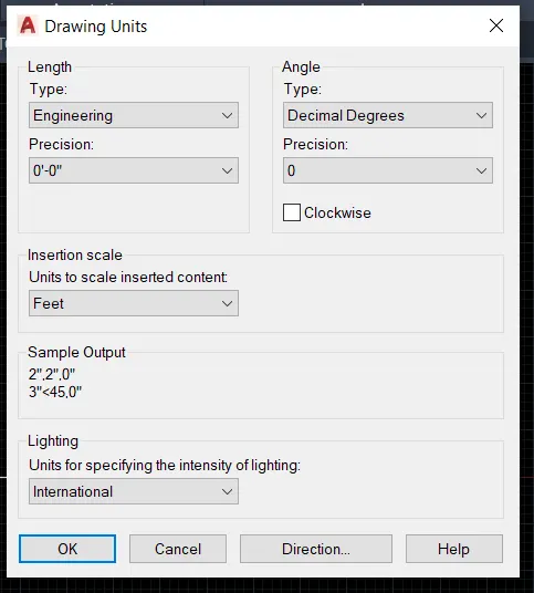
Create the column details:
RECTANGLE:
COMMAND: REC>
Specify first corner point: select the point on the window
Specify the other corner point: 24",24"
EXPLODE THE RECTANGLE:
COMMAND: EXPLODE>
Select object: select the rectangle>
OFFSET:
COMMAND: OFF>
Specify the offset distance: 1'
select the line and inside the offset four side
COMMAND: OFF>
Specify the offset distance: 5.69"'
select the line and inside the offset four side
COMMAND: OFF>
Specify the offset distance: 12.31"
select the lines and inside the offset two sides
SAME PROCEDURE FOR P1,P2,P3
CIRCLE:
COMMAND: C > t>
For creating the Rebers of P1
25mm= 1'
Specify point on the object for first tangent of circle: select Horizontal line
Specify point on the object for second tangent of circle: select vertical line
specify radius of circle: 0.5"
FOR ALL CORNERS OF P1 AS SAME
16mm= 0.62"
Specify point on the object for first tangent of circle: select Horizontal line
Specify point on the object for second tangent of circle: select vertical line
specify radius of circle: 0.31"
FOR ALL 16mm REBARS AS SAME IN P1
COMMAND: C > t>
For creating the rebars of P2
Specify point on the object for first tangent of circle: select Horizontal line
Specify point on the object for second tangent of circle: select vertical line
specify radius of circle: 0.31"
FOR ALL 16mm REBARS AS SAME IN P2
COMMAND: C > t>
For creating the rebars of P3
Specify point on the object for first tangent of circle: select Horizontal line
Specify point on the object for second tangent of circle: select vertical line
specify radius of circle: 0.5"
FOR ALL 25mm REBARS AS SAME IN P3
COMMAND: C > t>
For creating the rebars of P3
Specify point on the object for first tangent of circle: select Horizontal line
Specify point on the object for second tangent of circle: select vertical line
specify radius of circle: 0.395"
FOR ALL 20mm REBARS AS SAME IN P3
CREATE A TABLE:
INVOKING THE TABLE:
RIBBON > ANNOTATE> TABLE
COMMAND: TABLE>
Table with 2 columns and 4 rows.
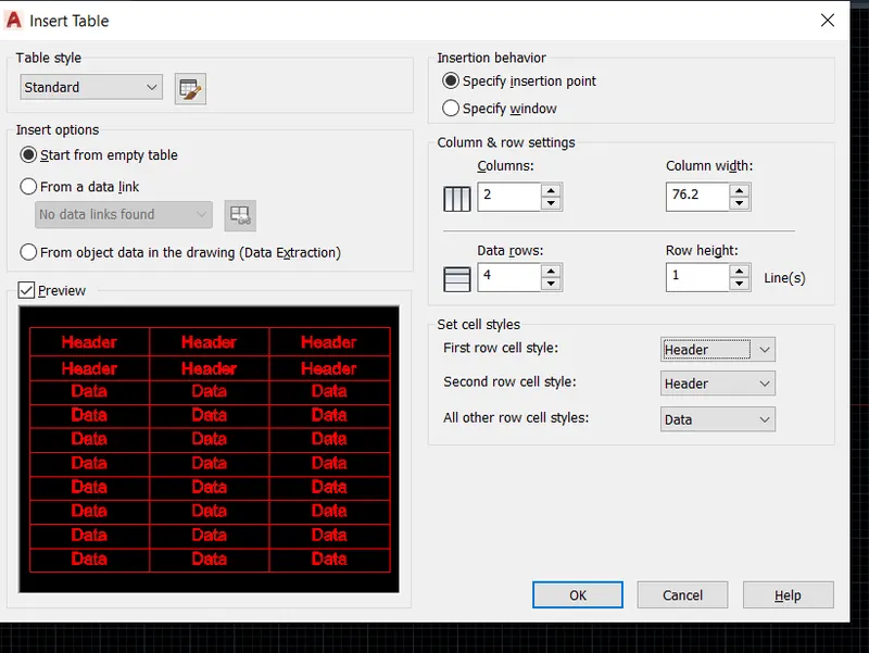
EDITING THE TABLE:
Edit the table as a required shape for scheduling the column details
Merging the tables and resize the table as per requirement.
TEXT:
Write the column details in the table box.
Insert the created column drawing in the table.
COLORING THE STRAPS: For easy understanding of the type of straps.
INVOKING THE TOOL
HOME tab> Properties > By layer
select the required color.
RESULT:
Sketching the given column schedule by using various tools and coomands.
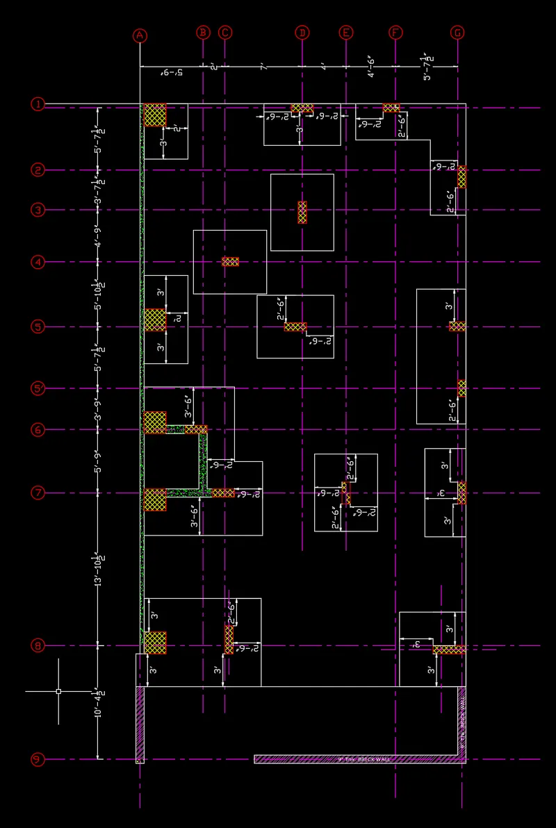
Q 5. Draw the Raft Layout as shown in the Figure. Assume the column size as per your knowledge. You can take the sizes as: 24”x24”, 9” x 24”, 9” x 18”, and 9’ x 24”. You can import the raft_foundation.pdf to ensure the missing dimensions.
AIM:
To Draw the Raft foundation Layout as shown in the figure.
REQUIRED TOOLS:
XLINE
OFFSET
TRIM
LINE
RECTANGLE
TEXT
HATCH
DIMENSIONS
PROCEDURE:
STEP-1
IMPORTING PDF FILES INTO DRAWING:
Importing the Raft foundation layout pdf file into the current drawing
INVOKING THE TOOL:
INSERT > PDF IMPORT > SELECT RESPECTED DOWNLOADED DRW. FILE >
STEP-2
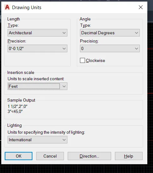
SETTING OUT UNITS:
COMMAND: UN>
UNITS: ARCHITECTURAL
PRECISION: 0'-0 1/2"
INSERTION SCALE: Feet
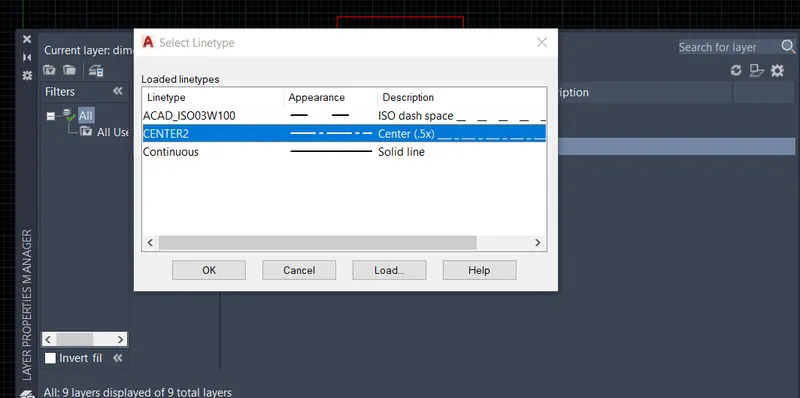
CREATE LAYERS:
Layer properties > New layer> linetype> CENTER2 Load the line type
CREATE GRID LINES:
XLINE:
COMMAND: XL>
Specify first point: select the point
Specify next point: Create a horizontal line
specify next point create one vertical line
OFFSET:
VERTICAL OFFSET LINES:
COMMAND: OFF>
Specify the offset distance: 5'-9"
select the line and right side the offset
COMMAND: OFF>
Specify the offset distance: 2'-0"
select the line and right side offset
COMMAND: OFF>
Specify the offset distance: 7'-0"
select the lines and right side the offset
Specify the offset distance: 4'-0"
select the line and right side the offset
COMMAND: OFF>
Specify the offset distance: 4'-6"
select the line and right side offset
COMMAND: OFF>
Specify the offset distance: 5'-7.5"
select the lines and right side the offset
HORIZONTAL OFFSET LINES:
COMMAND: OFF>
Specify the offset distance: 10'-4.5"
select the line and Upside the offset
COMMAND: OFF>
Specify the offset distance: 13'-10.5"
select the line and upside offset
COMMAND: OFF>
Specify the offset distance: 5'-9"
select the line and Upside the offset
COMMAND: OFF>
Specify the offset distance: 3'-9"
select the line and upside offset
COMMAND: OFF>
Specify the offset distance: 5'-7.5"
select the line and Upside the offset
COMMAND: OFF>
Specify the offset distance: 5'-10.5"
select the line and upside offset
COMMAND: OFF>
Specify the offset distance: 4'-9"
select the line and Upside the offset
COMMAND: OFF>
Specify the offset distance: 3'-7.5"
select the line and upside offset
COMMAND: OFF>
Specify the offset distance: 5'-7.5"
select the line and upside offset.
CREATE THE FOOTINGS AND COLUMNS:
Size of columns: 24" X 24" 9" X 24", 9" X 18"
Size of footings: taken the offset measurements from the reference drawing.
HATCHING:
COMMAND: H >
Select the required patterns > ANSI32 (For Brick wall)
Scale the Hatch pattern: based on drawing scale requirement
pick an internal point or [select object]:
COMMAND: H >
Select the required patterns > ARC-CONC (concrete)
Scale the Hatch pattern: based on drawing scale requirement
pick an internal point or [select object]:
COMMAND: H >
Select the required patterns > ANSI37 (column marking)
Scale the Hatch pattern: based on drawing scale requirement
pick an internal point or [select object]:
RESULT:
Sketch out the raft foundation layout by using the XLine command and other various commands.