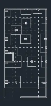
Creating a Wardrobe detailed drawing, Floor Plan, Kitchen Layout and Column Detail using AutoCad
1.
Aim: To draw a given cross section of wardrobe using autocad.
procedure: The following steps should be followed as a procedure to draw a given cross section of a wardrobe using autocad
- To draw the given cross section of a wardrobe in autocad, the following steps should be followed as a procedure. At first open the AutoCAD and set dimensions that the dimensions are in mm.
- Then enter the Line command in AutoCAD and after that enter the first point of the given diagram as that line should be started at the point in the coordinate system.
- Draw a rectangle using the autocad command enter the dimensions as per the given requirement as per the table.
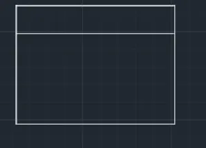
- Then with that point draw a rectangle using rectangle command using the dimensions of the rectangle as length is 2800 and width is 2100
- by using the offset command in autocad make offsset of 480 for the outer wall ie enter the dimension of the offset as 480.
- then select the last line of the rectangle and make offset of 12 ie the width of the both sides of the cross section of a wardrobe by using the offset command in autocad.
- next make offset of that line 1223 ie the width of the inner lines is equal to 1200, ie enter the offset command and give the width of 150.
- next make the offset of the line left corner of the rectangle to get the length of the inner spaces of the wardrobe by using the offset command in autocad give the offset lenth as 120 delete the unwanted lines by using the trim command in autocad.
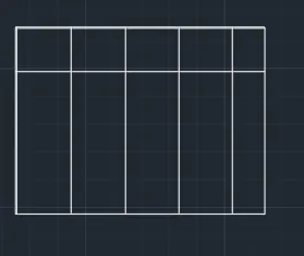
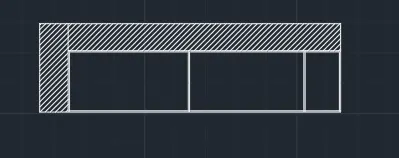
- draw the lines and the required lines by using the line command in the autocad then trim the extra lines as the required table that has been present in the wardrobe by using the line command or offset of the lines which has been present the lines is drawn and the extra lines which has been present is trim using the trim command in autocad then we get required lines in the wardbrobe as shown in the figure below.
- next make offset of that line 1223 ie the width of the inner lines is equal to 1200, ie enter the offset command and give the width of 150.
- next make the offset of the line left corner of the rectangle to get the length of the inner spaces of the wardrobe by using the offset command in autocad give the offset lenth as 120 delete the unwanted lines by using the trim command in autocad.then select the last line of the rectangle and make offset of 12 ie the width of the both sides of the cross section of a wardrobe by using the offset command in autocad.
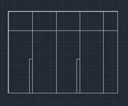
- and next by using the hatch command in autocad make the hatcing the required places as per the column ie enter the hatch command H enter and then select the required hatch pattern in the hatch settings and then scale it as per the diagram.
- continue the process of hatching for the remaing down cloumn remaning and then select the hatch serings and pattern as required as shown in the figure.
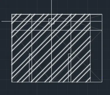
- copy the rectangle as given by using the copy command in the autocad and then select the centre line and then copy the rectangle.
- Draw a rectangle using the autocad command enter the dimensions as per the given requirement as per the table.
- Then with that point draw a rectangle using rectangle command using the dimensions of the rectangle as length is 2800 and width is 2100
- by using the offset command in autocad make offsset of 480 for the outer wall ie enter the dimension of the offset as 480.
- then select the last line of the rectangle and make offset of 12 ie the width of the both sides of the cross section of a wardrobe by using the offset command in autocad.
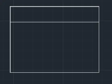
- draw the lines and the required lines by using the line command in the autocad then trim the extra lines as the required table that has been present in the wardrobe by using the line command or offset of the lines which has been present the lines is drawn and the extra lines which has been present is trim using the trim command in autocad then we get required lines in the wardbrobe as shown in the figure below.
- next make the offset of the line left corner of the rectangle to get the length of the inner spaces of the wardrobe by using the offset command in autocad give the offset lenth as 120 delete the unwanted lines by using the trim command in autocad.then select the last line of the rectangle and make offset of 12 ie the width of the both sides of the cross section of a wardrobe by using the offset command in autocad.
- Trim the unwanted lines for the door and the other openings the length of the line of that doors as per the given dimensions.
- Then enter the Line command in AutoCAD and after that enter the first point of the given diagram as that line should be started at the point in the coordinate system.
- next make offset of that line 300 ie the width of the inner setion of wardrobe is equal to 300, ie enter the offset command and give the width of 300.
- next make the offset of the line right corner of the rectangle to get the length of the another inner cross section of wardrobe by using the offset command in autocad give the offset lenth as 1180.
- next make offset of that line 300 ie the width of the inner cross secion of wardrobe is equal to 300, ie enter the offset command and give the width of 300
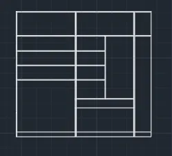
- and by using the multitext command or by copying the text which has been present in the another column the header text has been written or edited and edit the text as per the required and paste it on the row which has been present and edit the text and place the texting height as per the required table as shown in the figure below.
- and next by using the hatch command in autocad make the hatcing the required places as per the column ie enter the hatch command H enter and then select the required hatch pattern in the hatch settings and then scale it as per the diagram.
- continue the process of hatching for the remaing down wardbrobe cross section remaning and then select the hatch serings and pattern as required as shown in the figure.
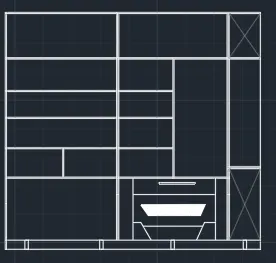
- next by using the rectangle command in autocad draw a rectangle in the fourth cloumn and then give the dimensions as per the table and the inner cross section as per the diagram and then make it offset of that rectangle to make it offset and then offset dimensions is taken as per the table and make the lines by using the circle command and then copy all the lines and then make sure that copy that lines in the required places as per the diagram.
- and next by using the hatch command in autocad make the hatcing the required places as per the column ie enter the hatch command H enter and then select the required hatch pattern in the hatch settings and then scale it as per the diagram.
- continue the process of hatching for the remaing down wardbrobe cross section remaning and then select the hatch serings and pattern as required as shown in the figure.
2.
To draw a given floor plan using autocad.
procedure: The following steps should be followed as a procedure to draw a given floor plan using autocad
- To draw the given floor plan in autocad, the following steps should be followed as a procedure. At first open the AutoCAD and set dimensions that the dimensions are in mm.
- Then enter the Line command in AutoCAD and after that enter the first point of the given diagram as that line should be started at the point in the coordinate system.
- Then with that point draw a rectangle using rectangle command using the dimensions of the rectangle as length is 3800 and width is 4350.
- by using the offset command in autocad make offsset of 230 for the outer wall ie enter the dimension of the offset as 230.
- then select the last line of the rectangle and make offset of 3830 ie the width of the both bedrooms by using the offset command in autocad.
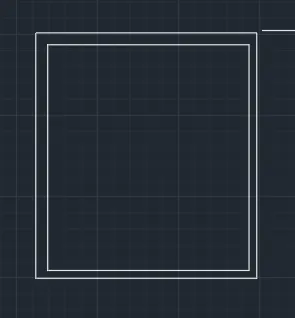
- next make offset of that line 150 ie the width of the inner wall is equal to 150, ie enter the offset command and give the width of 150.
- next make the offset of the line left corner of the rectangle to get the length of the bedrooms by using the offset command in autocad give the offset lenth as 150.
- next make offset of that line 150 ie the width of the inner wall is equal to 150, ie enter the offset command and give the width of 150.
- next make the offset of the line left corner of the rectangle to get the length of the bedrooms by using the offset command in autocad give the offset lenth as 150.
- Then with that point draw a rectangle using rectangle command using the dimensions of the rectangle as length is 1750 and width is 3000.
- by using the offset command in autocad make offsset of 230 for the outer wall ie enter the dimension of the offset as 230.
- then select the last line of the rectangle and make offset of 3830 ie the width of the both bedrooms by using the offset command in autocad.
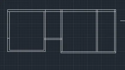
- next make offset of that line 150 ie the width of the inner wall is equal to 150, ie enter the offset command and give the width of 150.
- next make the offset of the line left corner of the rectangle to get the length of the bedrooms by using the offset command in autocad give the offset lenth as 150.
- next make offset of that line 150 ie the width of the inner wall is equal to 150, ie enter the offset command and give the width of 150.
- extend the line using the command extend that entre E double enter and select the line which has to be extended.
- connect the lines using the line command and close the entire walls of outer cross section by drawing the lines using the lines command.
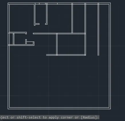
- next make offset of that line 2000 ie the width of the inner wall is equal to 3200, ie enter the offset command and give the width of 150.
- by using the offset command in autocad make offsset of 9" for the outer wall ie enter the dimension of the offset as 300.
- make the offet of 2150 and from that line make offset of 2000 to get the width of the living room and the kitchen and make offset from that line of 150 for the inner wall and 300 as the outer wall as diameter.
- Trim the unwanted lines for the door and the other openings the length of the line of that doors as per the given dimensions.
- for stair case make the offset of the line left corner of the rectangle to get the length of the staircase 300 and raiser 150 by using the offset command in autocad give the offset lenth as 150.
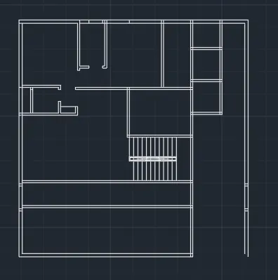
- next make the offset of the line to get the length of the toilets by using the offset command in autocad give the offset lenth as 150 in both sides.
- next make the offset of the line left corner of the rectangle to get the length of the one of the bathrooms by using the offset command in autocad give the offset lenth as 5310.
- next make the offset of the line right corner of the rectangle to get the length of the another bathroom by using the offset command in autocad give the offset lenth as 9510.
- next make offset of that line 150 ie the width of the inner wall is equal to 300 ie enter the offset command and give the width of 150
- delete the unwanted lines by using the trim command in autocad.
- next make the offset of the line right corner of the rectangle to get the length of the another bathroom by using the offset command in autocad give the offset lenth as 1570.
- next make offset of that line 1500 ie the width of the inner walls of lift is equal to 1600, ie enter the offset command and give the width of 150
- by using the offset command in autocad make offsset of 300 for the outer wall ie enter the dimension of the offset as 300.
- make the offet of 2000 and from that line make offset of 3200 to get the width of the living room and the kitchen and make offset from that line of 150 for the inner wall and 300 as the outer wall as diameter.
- Trim the unwanted lines for the door and the other openings the length of the line of that doors as per the given dimensions.
- next make offset of that line 2000 ie the width of the inner wall is equal to 3200, ie enter the offset command and give the width of 150.
- by using the offset command in autocad make offsset of 9" for the outer wall ie enter the dimension of the offset as 300.
- make the offet of 2150 and from that line make offset of 2000 to get the width of the living room and the balcony and make offset from that line of 150 for the inner wall and 300 as the outer wall as diameter.
- Trim the unwanted lines for the door and the other openings the length of the line of that doors as per the given dimensions.
- for stair case make the offset of the line left corner of the rectangle to get the length of the staircase 300 and raiser 150 by using the offset command in autocad give the offset lenth as 150.
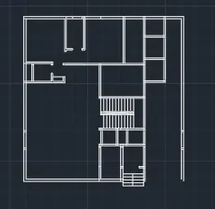
- next by using the rectangle command in autocad draw a rectangle in the fourth cloumn and then give the dimensions as per the table and the inner cross section as per the diagram and then make it offset of that rectangle to make it offset and then offset dimensions is taken as per the table and make the lines by using the circle command and then copy all the lines and then make sure that copy that lines in the required places as per the diagram.
- and next by using the hatch command in autocad make the hatcing the required places as per the column ie enter the hatch command H enter and then select the required hatch pattern in the hatch settings and then scale it as per the diagram.
- continue the process of hatching for the remaing down wall inner and outer cross section remaning and then select the hatch serings and pattern as required as shown in the figure.
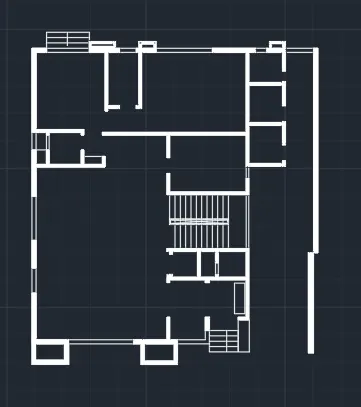
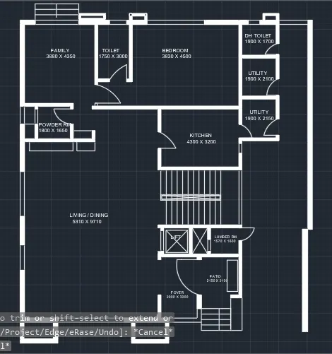
- and by using the multitext command or by copying the text which has been present in the another column the header text has been written sizes of the rooms or edited and edit the text as per the required and paste it on the row which has been present and edit the text and place the texting height as per the required table as shown in the figure below.
- edit the text as per the required and paste it on the row which has been present and edit the text and place the texting height as per the required table as shown in the figure below.
- to draw the door by using the autocad commands that by line command we can draw the line and by arc command we can draw the arc and by rectangle command we can draw the chouckets and then trim the unwanted lines. repeat the process for each and every door point side as per the required floor plan.
- enter the dimensions of the rooms as per the given dimensions using the Multi text command in autocad and enter the dimensions wich is required in the given floor plan to gte the required floor plan of the bathrooms and vanity and all other rooms.
- and by using the multitext command or by copying the text which has been present in the another column the header text has been written sizes of the rooms or edited and edit the text as per the required and paste it on the row which has been present and edit the text and place the texting height as per the required table as shown in the figure below.
3.
Aim: To draw a given cross section of kitchen using autocad.
procedure: The following steps should be followed as a procedure to draw a given cross section of a kitchen using autocad
- To draw the given cross section of a kitchen in autocad, the following steps should be followed as a procedure. At first open the AutoCAD and set dimensions that the dimensions are in mm.
- Then enter the Line command in AutoCAD and after that enter the first point of the given diagram as that line should be started at the point in the coordinate system.
- Draw a rectangle using the autocad command enter the dimensions as per the given requirement as per the table.
- Then with that point draw a rectangle using rectangle command using the dimensions of the rectangle as length is 4300 and width is 2300
- by using the offset command in autocad make offsset of 480 for the outer wall ie enter the dimension of the offset as 480.
- then select the last line of the rectangle and make offset of 12 ie the width of the both sides of the cross section of a wardrobe by using the offset command in autocad.
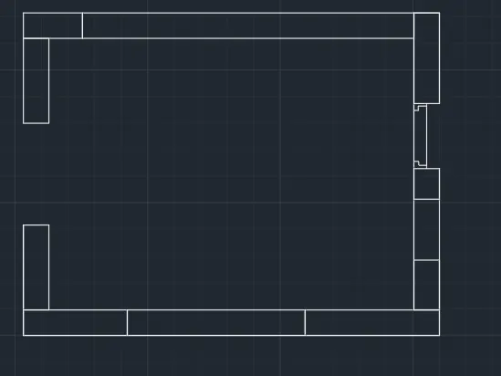
- next make offset of that line 600 ie the width of the inner lines is equal to 450, ie enter the offset command and give the width of 300.
- next make the offset of the line left corner of the rectangle to get the length of the inner spaces of the wardrobe by using the offset command in autocad give the offset lenth as 300 delete the unwanted lines by using the trim command in autocad.
- next make the offset of the line left corner of the rectangle to get the length of the one of the bathrooms by using the offset command in autocad give the offset lenth as 450.
- next make the offset of the line right corner of the rectangle to get the length of the another bathroom by using the offset command in autocad give the offset lenth as 900.
- next make offset of that line 450 ie the width of the inner wall is equal to 300 ie enter the offset command and give the width of 450
- delete the unwanted lines by using the trim command in autocad.
- next make the offset of the line right corner of the rectangle to get the length of the another bathroom by using the offset command in autocad give the offset lenth as 945.
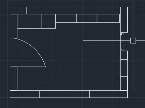
- to draw the door by using the autocad commands that by line command we can draw the line and by arc command we can draw the arc and by rectangle command we can draw the chouckets and then trim the unwanted lines. repeat the process for each and every door point side as per the required floor plan.
- enter the dimensions of the rooms as per the given dimensions using the Multi text command in autocad and enter the dimensions wich is required in the given floor plan to gte the required floor plan of the bathrooms and vanity and all other rooms.
- next make offset of that line 600 ie the width of the inner lines is equal to 450, ie enter the offset command and give the width of 300.
- next make the offset of the line left corner of the rectangle to get the length of the inner spaces of the wardrobe by using the offset command in autocad give the offset lenth as 300 delete the unwanted lines by using the trim command in autocad.
- next make the offset of the line left corner of the rectangle to get the length of the one of the bathrooms by using the offset command in autocad give the offset lenth as 450.
- next make the offset of the line right corner of the rectangle to get the length of the another bathroom by using the offset command in autocad give the offset lenth as 900.
- next make offset of that line 450 ie the width of the inner wall is equal to 300 ie enter the offset command and give the width of 450
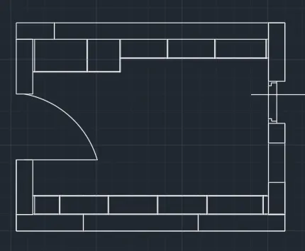
- give the dimensions of that usimg the dimensions settings in autocad and then make the settings in the annatation as shown in the figure below.
- and by using the multitext command or by copying the text which has been present in the another column the header text has been written size or edited and edit the text as per the required and paste it on the row which has been present and edit the text and place the texting height as per the required table as shown in the figure below.
- edit the text as per the required and paste it on the row which has been present and edit the text and place the texting height as per the required table as shown in the figure below.
- to draw the door by using the autocad commands that by line command we can draw the line and by arc command we can draw the arc and by rectangle command we can draw the chouckets and then trim the unwanted lines. repeat the process for each and every door point side as per the required kitchen cross section.
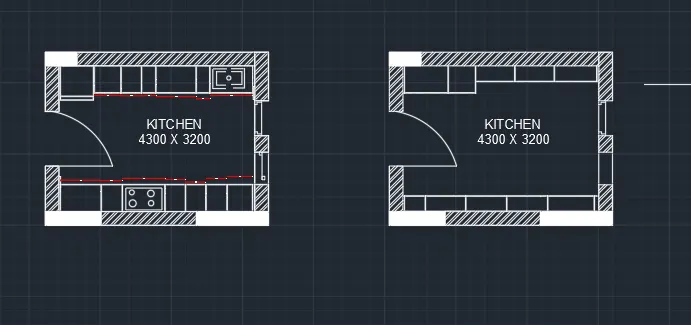
- enter the dimensions of the kitchen cross section as per the given dimensions using the Multi text command in autocad and enter the dimensions wich is required in the given floor plan to gte the required floor plan of the bathrooms and vanity and all other rooms.
- and by using the multitext command or by copying the text which has been present in the another column the header text has been written sizes of the rooms or edited and edit the text as per the required and paste it on the row which has been present and edit the text and place the texting height as per the required table as shown in the figure below.
4.
Aim: To draw a given table schdule using autocad.
procedure: The following steps should be followed as a procedure to draw a given section table using autocad
- To draw the given section table in autocad, the following steps should be followed as a procedure. At first open the AutoCAD and set dimensions that the dimensions are in feets and inches.
- Then enter the Line command in AutoCAD and after that enter the first point of the given diagram as that line should be started at the point in the coordinate system.
- Draw a rectangle using the autocad command enter the dimensions as per the given requirement as per the table.
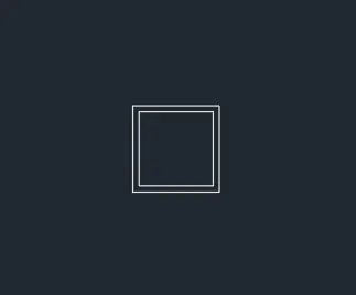
- Draw the outer dimensions given by the table by using line command in autocad ie draw the lines and draw the inner and outer lines by using the autocad command.
- Draw the outer dimensions given by the table by using line command in autocad ie draw the lines and draw the inner and outer lines by using the autocad command.
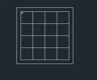
- Draw a rectangle using the autocad command enter the dimensions as per the given requirement as per the table.
- Draw the outer dimensions given by the table by using line command in autocad ie draw the lines and draw the inner and outer lines by using the autocad command.
- Draw the outer dimensions given by the table by using line command in autocad ie draw the lines and draw the inner and outer lines by using the autocad command.
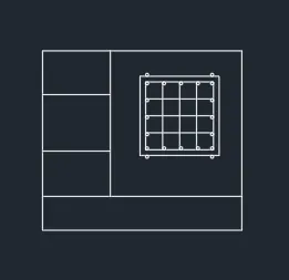
- Draw the outer dimensions given by the table by using line command in autocad ie draw the lines and draw the inner and outer lines by using the autocad command.
- by using the multi text command in auocad by selecting the multi text command then using the settings option we can get the size of the text given.
- draw the bottom line and the required lines by using the line command in the autocad then trim the extra lines as the required table.
- rotate the text which has been given as per the table and then make sure that the text settings which has been make as per the table settings and make sure that the text heatings is in bold in the settings os annative in the autocad.
- draw the bottom line and the required lines by using the line command in the autocad then trim the extra lines as the required table.
- draw the lines and the required lines by using the line command in the autocad then trim the extra lines as the required table that has been present in the table by using the line command or offset of the lines which has been present the lines is drawn and the extra lines which has been present is trim using the trim command in autocad then we get required lines in the table as shown in the figure below.
- and by using the multitext command or by copying the text which has been present in the another column the header text has been written or edited and edit the text as per the required and paste it on the row which has been present and edit the text and place the texting height as per the required table as shown in the figure below.
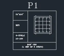
- Draw the outer dimensions given by the table by using line command in autocad ie draw the lines and draw the inner and outer lines by using the autocad command.
- by using the multi text command in auocad by selecting the multi text command then using the settings option we can get the size of the text given.
- draw the bottom line and the required lines by using the line command in the autocad then trim the extra lines as the required table.
- rotate the text which has been given as per the table and then make sure that the text settings which has been make as per the table settings and make sure that the text heatings is in bold in the settings os annative in the autocad.
- draw the bottom line and the required lines by using the line command in the autocad then trim the extra lines as the required table.
- draw the lines and the required lines by using the line command in the autocad then trim the extra lines as the required table that has been present in the table by using the line command or offset of the lines which has been present the lines is drawn and the extra lines which has been present is trim using the trim command in autocad then we get required lines in the table as shown in the figure below.
- and by using the multitext command or by copying the text which has been present in the another column the header text has been written or edited and edit the text as per the required and paste it on the row which has been present and edit the text and place the texting height as per the required table as shown in the figure below.
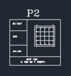
- next by using the rectangle command in autocad draw a rectangle in the fourth cloumn and then give the dimensions as per the table and the size of the column as per the table and then make it offset of that rectangle to make it offset and then offset dimensions is taken as per the table and make the circles by using the circle command and then copy all the circles and then make sure that copy that circles in the required places as per the table.
- and draw the remaing circles by using the circle command in the autocad and then copy the circles and place it as per the table.
- and by using the multitext command or by copying the text which has been present in the another column the header text has been written or edited and edit the text as per the required and paste it on the row which has been present and edit the text and place the texting height as per the required table as shown in the figure below.
- and by using the multitext command or by copying the text which has been present in the another column the header text has been written or edited and edit the text as per the required and paste it on the row which has been present and edit the text and place the texting height as per the required table as shown in the figure below.
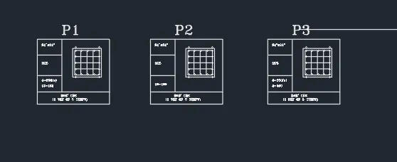
- draw and complete the table by using the command and then edit the tables by using multi text commands as shown in figure below.
5.
To draw a given floor plan column cross section placing schdule using autocad.
procedure: The following steps should be followed as a procedure to draw a given floor plan column cross section placing schdule using autocad
- To draw the given floor plan column cross section placing schdule in autocad, the following steps should be followed as a procedure. At first open the AutoCAD and set dimensions that the dimensions are in feets and inches.
- Then enter the Line command in AutoCAD and after that enter the first point of the given diagram as that line should be started at the point in the coordinate system.
- Then with that point draw a rectangle using rectangle command using the dimensions of the rectangle as length is and width is 26.
- by using the offset command in autocad make offsset of 4.5" for the outer wall ie enter the dimension of the offset as 4.5".
- then select the last line of the rectangle and make offset of 9" ie the width of the both sides by using the offset command in autocad.
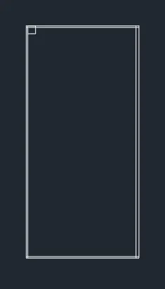
- next make offset of that line 5'9" ie the width of the inner lines is equal to 2', ie enter the offset command and give the width of 7' ans in the line seetings select the required line type to change the line type .
- next make the offset of the line left corner of the rectangle to get the length of the inner spaces of the wardrobe by using the offset command in autocad give the offset lenth as 4'6" delete the unwanted lines by using the trim command in autocad in the line seetings select the required line type to change the line type.
- next make the offset of the line left corner of the rectangle to get the length of the one of the liner lines of the column by using the offset command in autocad give the offset lenth as 5'7.5" in the line seetings select the required line type to change the line type.
- next make the offset of the line right corner of the rectangle to get the length of the another in the line seetings select the required line type to change the line type by using the offset command in autocad give the offset lenth as 4'9" in the line seetings select the required line type to change the line type.
- next make offset of that line 5'10.5" ie the width of the inner wall is equal to 5'7.5" ie enter the offset command and give the width of 3'9" in the line seetings select the required line type to change the line type
- delete the unwanted lines by using the trim command in autocad in the line seetings select the required line type to change the line type.
- next make the offset of the line right corner of the rectangle to get the length of the another in the line seetings select the required line type to change the line type by using the offset command in autocad give the offset lenth as 13'10.5" in the line seetings select the required line type to change the line type.
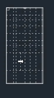
- next make the offset of the line left corner of the rectangle to get the length of the one of the liner lines of the column by using the offset command in autocad give the offset lenth as 3'7.5" in the line seetings select the required line type to change the line type.
- next make the offset of the line right corner of the rectangle to get the length of the another in the line seetings select the required line type to change the line type by using the offset command in autocad give the offset lenth as 4'9" in the line seetings select the required line type to change the line type.
- next make offset of that line 5'10.5" ie the width of the inner wall is equal to 5'7.5" ie enter the offset command and give the width of 3'9" in the line seetings select the required line type to change the line type
- place the columns as per the required places and then make that copy all the columns and rotate as per the required schdule column cross section placing.
- delete the unwanted lines by using the trim command in autocad in the line seetings select the required line type to change the line type.
- next make the offset of the line right corner of the rectangle to get the length of the another in the line seetings select the required line type to change the line type by using the offset command in autocad give the offset lenth as 13'10.5" in the line seetings select the required line type to change the line type.
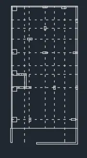
- next make offset of that line 2.5' ie the width of the inner lines is equal to 2', ie enter the offset command and give the width of 3' ans in the line seetings select the required line type to change the line type .
- next make the offset of the line left corner of the rectangle to get the length of the inner spaces of the wardrobe by using the offset command in autocad give the offset lenth as 3' delete the unwanted lines by using the trim command in autocad in the line seetings select the required line type to change the line type.
- next make the offset of the line left corner of the rectangle to get the length of the one of the liner lines of the column by using the offset command in autocad give the offset lenth as 2.5' in the line seetings select the required line type to change the line type.
- next make the offset of the line right corner of the rectangle to get the length of the another in the line seetings select the required line type to change the line type by using the offset command in autocad give the offset lenth as 3'6" in the line seetings select the required line type to change the line type.
- next make offset of that line 2'10.5" ie the width of the inner wall is equal to 2'7.5" ie enter the offset command and give the width of 3'6" in the line seetings select the required line type to change the line type
- and next by using the hatch command in autocad make the hatcing the required places as per the column ie enter the hatch command H enter and then select the required hatch pattern in the hatch settings and then scale it as per the diagram.
- continue the process of hatching for the remaing down wall inner and outer cross section remaning and then select the hatch serings and pattern as required as shown in the figure.
- and next by using the hatch command in autocad make the hatcing the required places as per the column ie enter the hatch command H enter and then select the required hatch pattern in the hatch settings and then scale it as per the diagram.
- continue the process of hatching for the remaing down wall inner and outer cross section remaning and then select the hatch serings and pattern as required as shown in the figure.
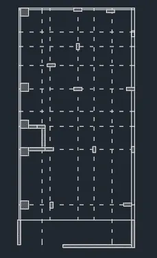
- next make offset of that line 2.5' ie the width of the inner lines is equal to 2', ie enter the offset command and give the width of 3' ans in the line seetings select the required line type to change the line type .
- next make the offset of the line left corner of the rectangle to get the length of the inner spaces of the wardrobe by using the offset command in autocad give the offset lenth as 3' delete the unwanted lines by using the trim command in autocad in the line seetings select the required line type to change the line type.
- next make the offset of the line left corner of the rectangle to get the length of the one of the liner lines of the column by using the offset command in autocad give the offset lenth as 2.5' in the line seetings select the required line type to change the line type.
- next make the offset of the line right corner of the rectangle to get the length of the another in the line seetings select the required line type to change the line type by using the offset command in autocad give the offset lenth as 3'6" in the line seetings select the required line type to change the line type.
- next make offset of that line 2'10.5" ie the width of the inner wall is equal to 2'7.5" ie enter the offset command and give the width of 3'6" in the line seetings select the required line type to change the line type
- and next by using the hatch command in autocad make the hatcing the required places as per the column ie enter the hatch command H enter and then select the required hatch pattern in the hatch settings and then scale it as per the diagram.
- continue the process of hatching for the remaing down wall inner and outer cross section remaning and then select the hatch serings and pattern as required as shown in the figure.
- and next by using the hatch command in autocad make the hatcing the required places as per the column ie enter the hatch command H enter and then select the required hatch pattern in the hatch settings and then scale it as per the diagram.
- continue the process of hatching for the remaing down wall inner and outer cross section remaning and then select the hatch settings and pattern as required as shown in the figure.