Creating a Wardrobe detailed drawing, Floor Plan, Kitchen Layout and Column Detail using AutoCad
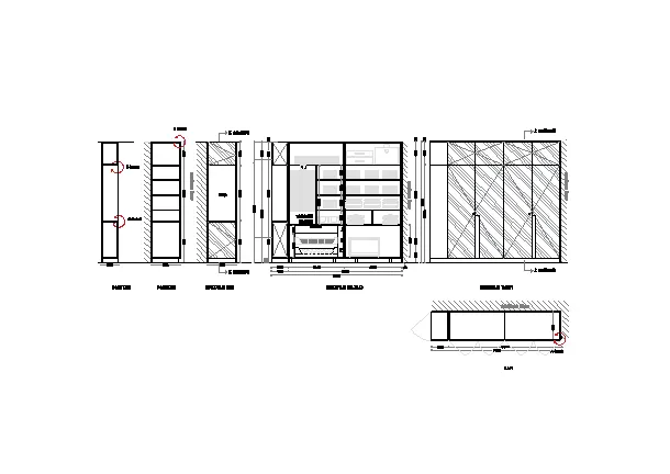
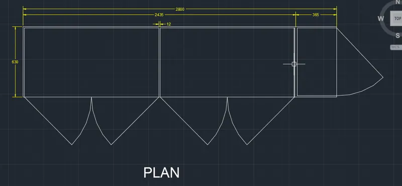
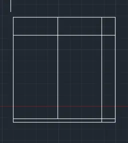
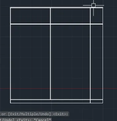
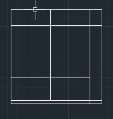
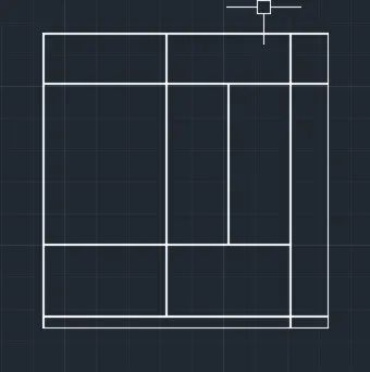
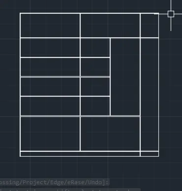
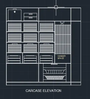
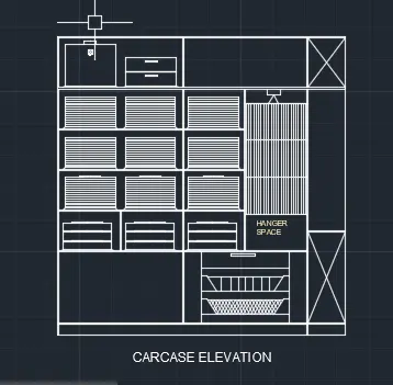
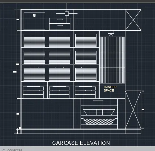
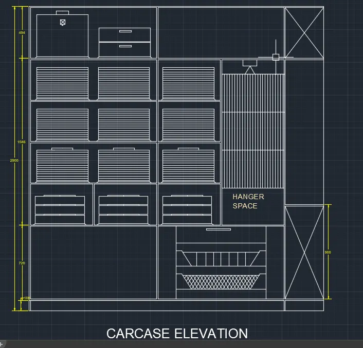
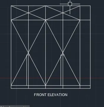
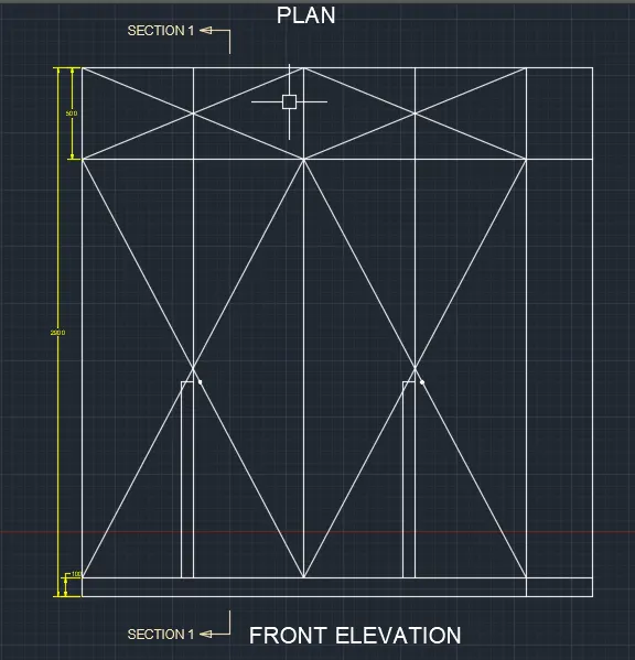
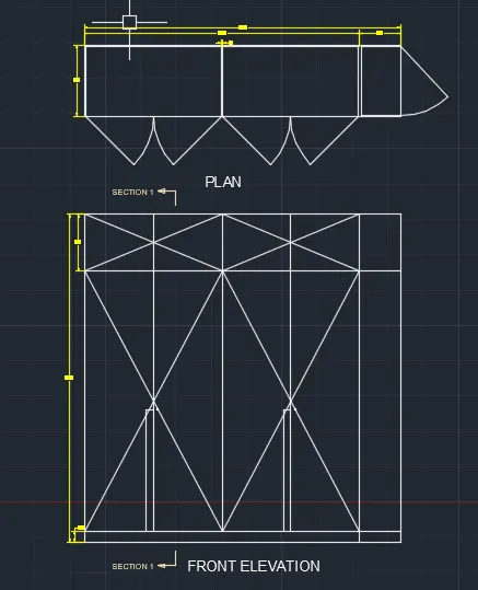
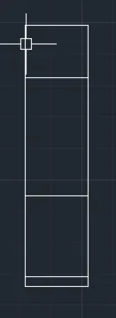
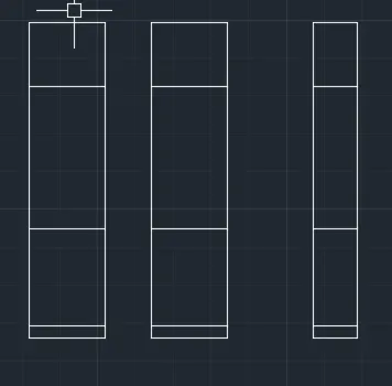
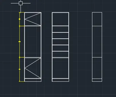
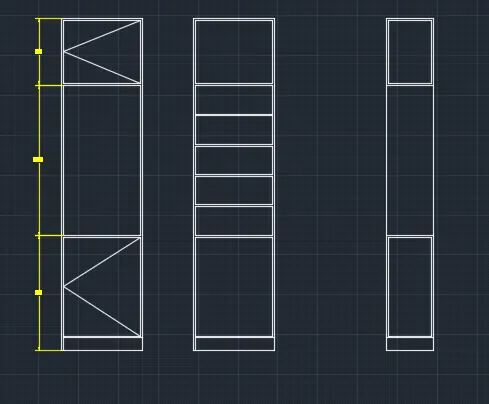
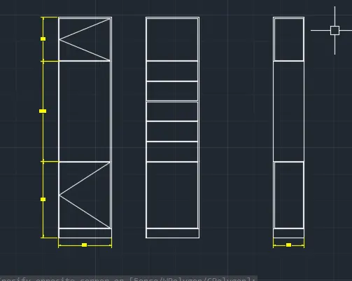
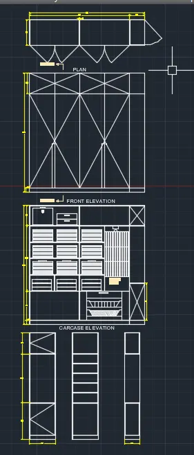
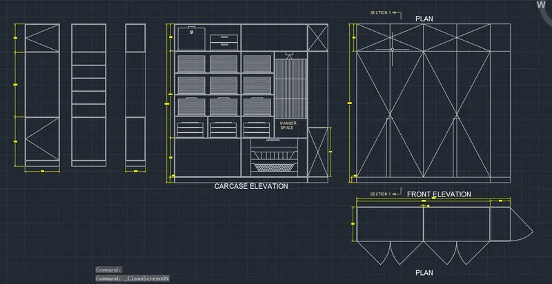
1. Draw the elevation and details of a wardrobe as shown in the Figure below. After sketching, you need to provide the dimensions and text with the use of layers. Use proper text styles and dimension methods to document it. Also, assume dimensions, wherever needed.
Note: All dimensions are in mm.
AIM :
Draw the elevation and details of a wardrobe as shown in the Figure By useing AUTOCAD Tool
PROCEDURE :
Draw the elevation and details of a wardrobe as shown in the Figure below. After sketching, you need to provide the dimensions and text with the use of layers. Use proper text styles and dimension methods to document it. Also, assume dimensions, wherever needed.
Note: All dimensions are in mm.
OPEN ATOCAD
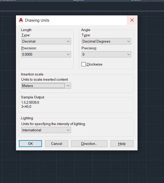
CHENGE UNITS AS YOUR REQURED
Units command UN Enter chenge units asyour requred
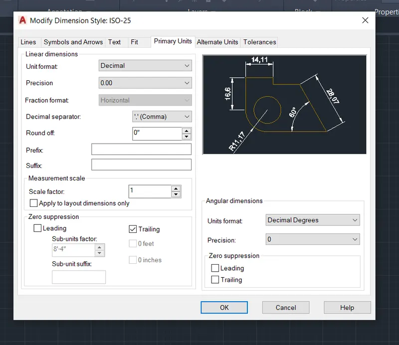
next DIMSTYLE
Next limits
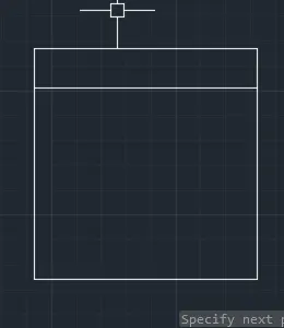
Command: L
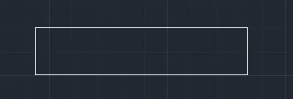
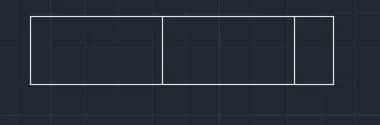
LINE
Specify first point:
Specify next point or [Undo]: 2800
Specify next point or [Undo]: 630
Specify next point or [Close/Undo]: 2800
Specify next point or [Close/Undo]: C
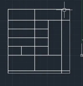
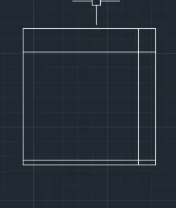
Command: O
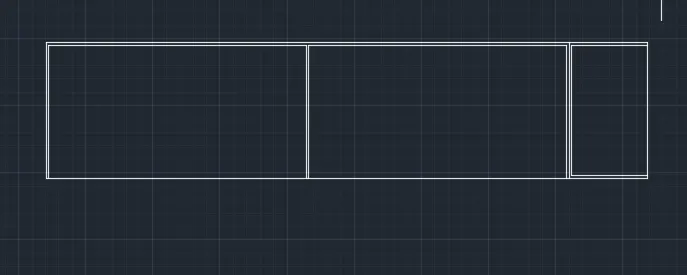
OFFSET
Current settings: Erase source=No Layer=Source OFFSETGAPTYPE=0
Specify offset distance or [Through/Erase/Layer] <365.0000>: 365
Select object to offset or [Exit/Undo] <Exit>:
Specify point on side to offset or [Exit/Multiple/Undo] <Exit>:
Select object to offset or [Exit/Undo] <Exit>:
Command: Specify opposite corner or [Fence/WPolygon/CPolygon]:
Command: CO
COPY 1 found
Current settings: Copy mode = Multiple
Specify base point or [Displacement/mOde] <Displacement>:
>>Enter new value for ORTHOMODE <1>:
Resuming COPY command.
Specify base point or [Displacement/mOde] <Displacement>:
Specify second point or [Array] <use first point as displacement>: _m2p First point of mid: Second point of mid:
Specify second point or [Array/Exit/Undo] <Exit>: *Cancel*
Command: O
OFFSET
Current settings: Erase source=No Layer=Source OFFSETGAPTYPE=0
Specify offset distance or [Through/Erase/Layer] <365.0000>: 12
Select object to offset or [Exit/Undo] <Exit>:
Specify point on side to offset or [Exit/Multiple/Undo] <Exit>:
Select object to offset or [Exit/Undo] <Exit>:
Specify point on side to offset or [Exit/Multiple/Undo] <Exit>:
Select object to offset or [Exit/Undo] <Exit>:
Specify point on side to offset or [Exit/Multiple/Undo] <Exit>:
Select object to offset or [Exit/Undo] <Exit>:
Specify point on side to offset or [Exit/Multiple/Undo] <Exit>:
Select object to offset or [Exit/Undo] <Exit>:
Specify point on side to offset or [Exit/Multiple/Undo] <Exit>:
Select object to offset or [Exit/Undo] <Exit>: *Cancel*
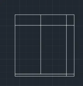
Command: O
OFFSET
Current settings: Erase source=No Layer=Source OFFSETGAPTYPE=0
Specify offset distance or [Through/Erase/Layer] <12.0000>: 6
Select object to offset or [Exit/Undo] <Exit>:
Specify point on side to offset or [Exit/Multiple/Undo] <Exit>:
Select object to offset or [Exit/Undo] <Exit>:
Specify point on side to offset or [Exit/Multiple/Undo] <Exit>:
Select object to offset or [Exit/Undo] <Exit>: *Cancel*
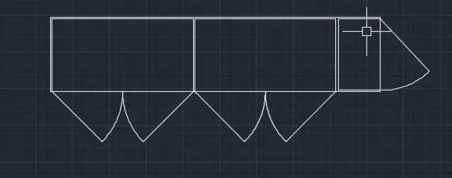
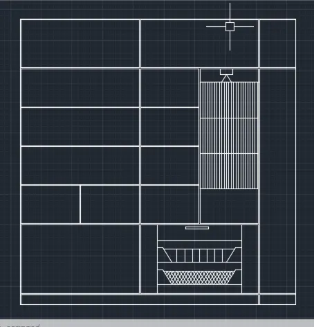
Command: F
FILLET
Current settings: Mode = TRIM, Radius = 0.0000
Select first object or [Undo/Polyline/Radius/Trim/Multiple]:
Select second object or shift-select to apply corner or [Radius]:
SECTION
Command: L
LINE
Specify first point:
Specify next point or [Undo]: 2800
Specify next point or [Undo]: 500
Specify next point or [Close/Undo]: 2400
Specify next point or [Close/Undo]: 2800
Specify next point or [Close/Undo]: C
Command: L
LINE
Specify first point:
Specify next point or [Undo]:
Specify next point or [Undo]: *Cancel*
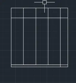
Command: O
OFFSET
Current settings: Erase source=No Layer=Source OFFSETGAPTYPE=0
Specify offset distance or [Through/Erase/Layer] <6.0000>: 365
Select object to offset or [Exit/Undo] <Exit>:
Specify point on side to offset or [Exit/Multiple/Undo] <Exit>:
Select object to offset or [Exit/Undo] <Exit>:
Specify point on side to offset or [Exit/Multiple/Undo] <Exit>:
Select object to offset or [Exit/Undo] <Exit>: *Cancel*
RESULT :
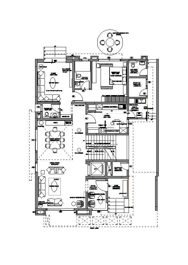
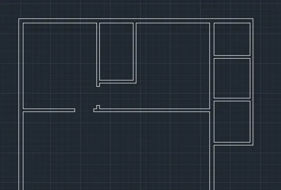
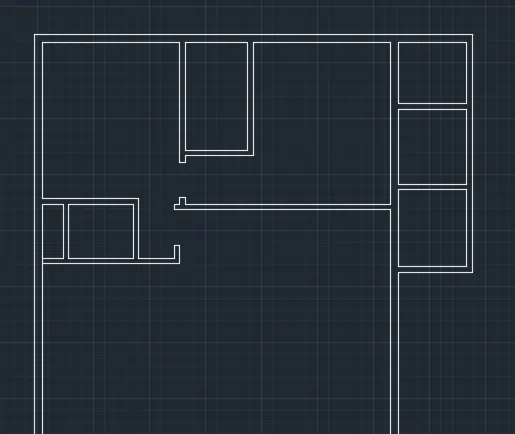
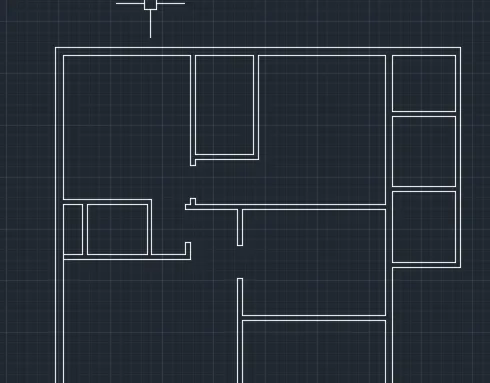
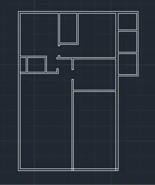
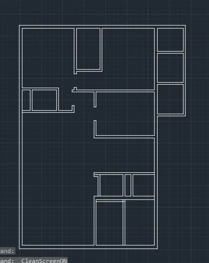
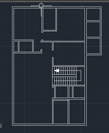
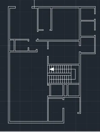
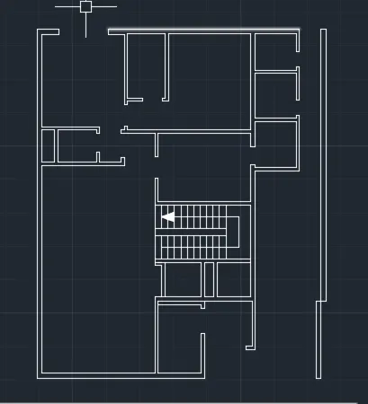
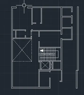
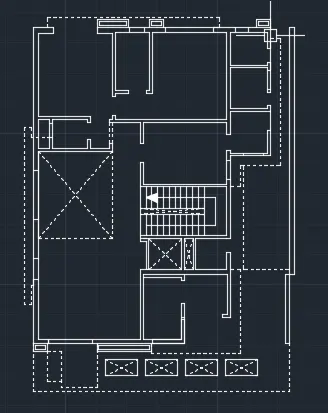
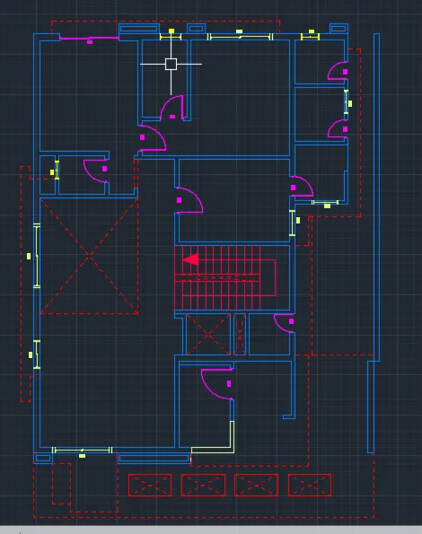
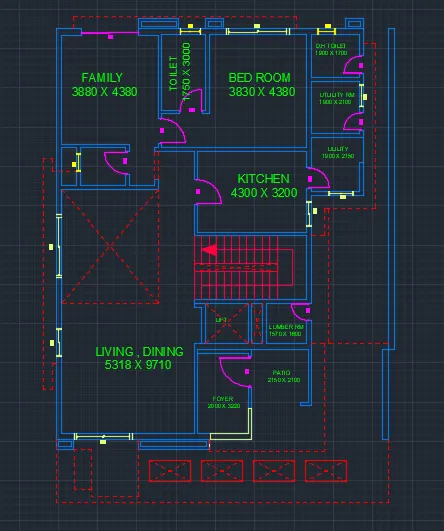
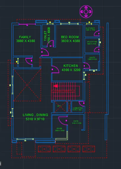
Q2. Draw the floor plan as shown in the Figure. Use the proper drafting tools to sketch the plan. Do not hatch or draw the furniture. You need to draw the floor plan with the following:
Note: You can also import the Floor_Plan.pdf into your current drawing and start working on the project. You need to scale the imported pdf file using reference option. All dimensions are in mm.
- Walls (Exterior and Interior)
Wall Thickness: Exterior Wall- 230mm, Interior Wall: 150 mm (Wherever Required)
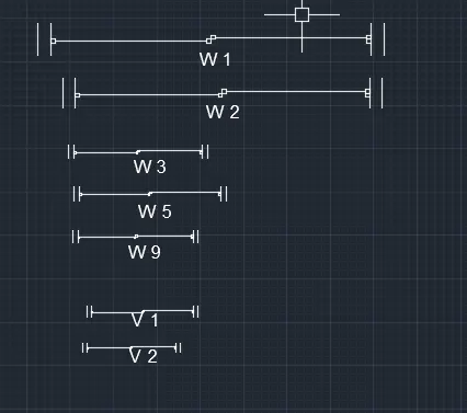
- Doors and Windows: Assume the size of the doors and window.
2.1 Stairs: Tread-300mm, Riser-150mm
- Insert Text wherever required
- Insert the dimensions using proper dimension techniques
AIM :
THE FLOOR PLAN SHOWN HERE IS DONE WITH THE HELP OF THE FOLLOWING AUTOCAD TOOLS
PROCEDURE :
Note: You can also import the Floor_Plan.pdf into your current drawing and start working on the project. You need to scale the imported pdf file using reference option. All dimensions are in mm.
- Walls (Exterior and Interior)
Wall Thickness: Exterior Wall- 230mm
Interior Wall: 150 mm (Wherever Required)
- Doors and Windows: Assume the size of the doors and window.
2.1 Stairs: Tread-300mm, Riser-150mm
- Insert Text wherever required
- Insert the dimensions using proper dimension techniques
OPEN ATOCAD
CHENGE UNITS AS YOUR REQURED
Units command UN Enter chenge units asyour requred
next DIMSTYLE
Next limits
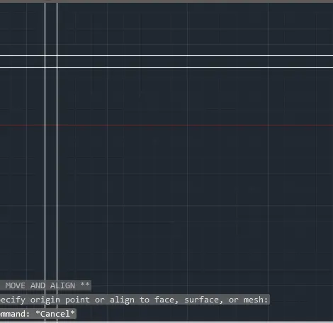
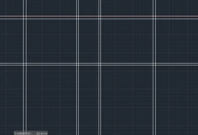
- THE OUTER LINE OF THE PLAN IS FIRST MARKED WITH THE HELP OF HOROZONTAL AND VERTICAL CONSTRUTION LINES.
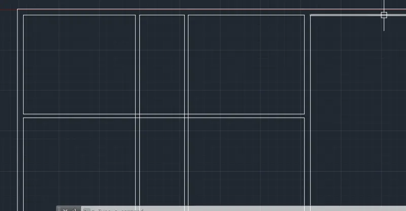
- AN OFFSET OF 230mm FOR EXTRINAL WALL AND 150mm FOR INTERNAL WALLS.
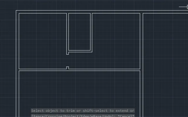
- BESED ON THE DIMENSIONS OF THE ROOM MENTIONED ANOTHER OFFSET IS DRAWN FOR WHICH A WALL OFFSET OF EITHER 150 OR 230mm IS DRAWN TO CREATE A ROOMS OF REQUIURED DIMENSION.
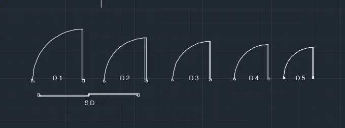
- THE DOORS ARE DRAWN WITH THE HELP OF LINE AND ARC TOOL.
- THE DOTTED LINES ARE DRAWN BY SELECTION THE LINE TYPE AND ADJUSTING THE SCALE OF THE LINE AS WELL.
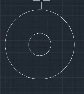
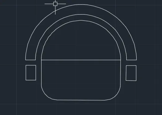
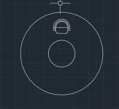
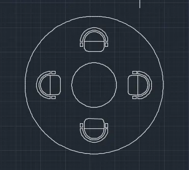
- THE OUTER SITTING TABLE IS DRAWN WITH THE HELP OF CIRCLE , LINE , AND ARC TOOLS.
- THE UNWANTED LINES AND TRIMMED AND DELETED LATER.
RESULT :
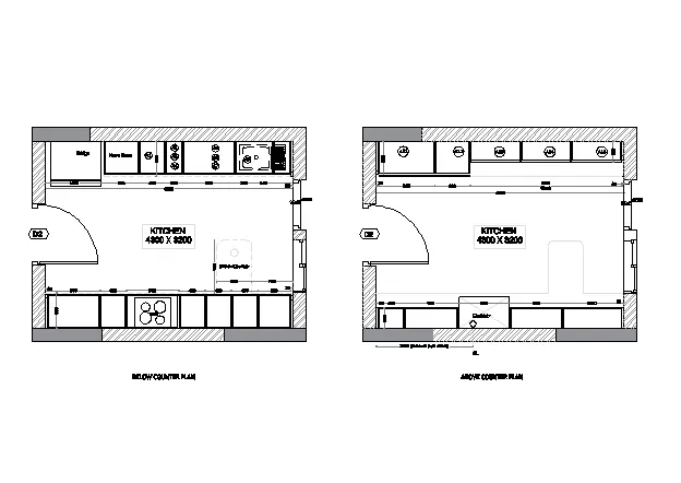
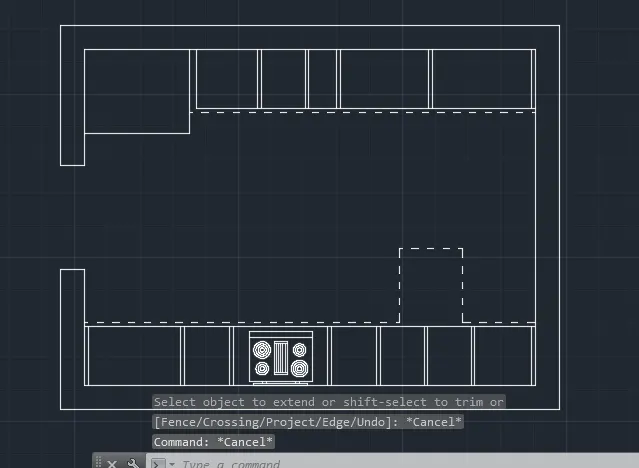
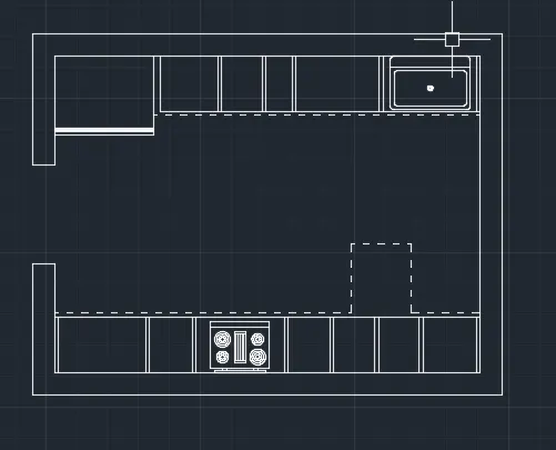
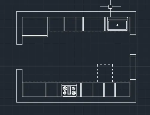
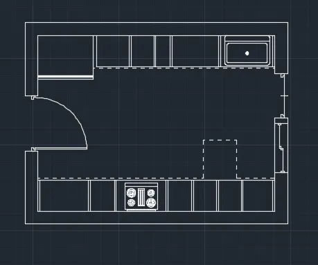
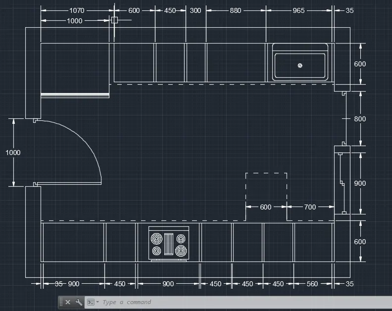
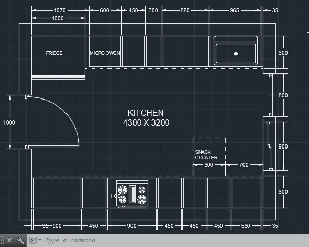
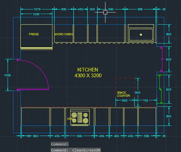
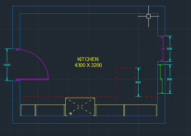
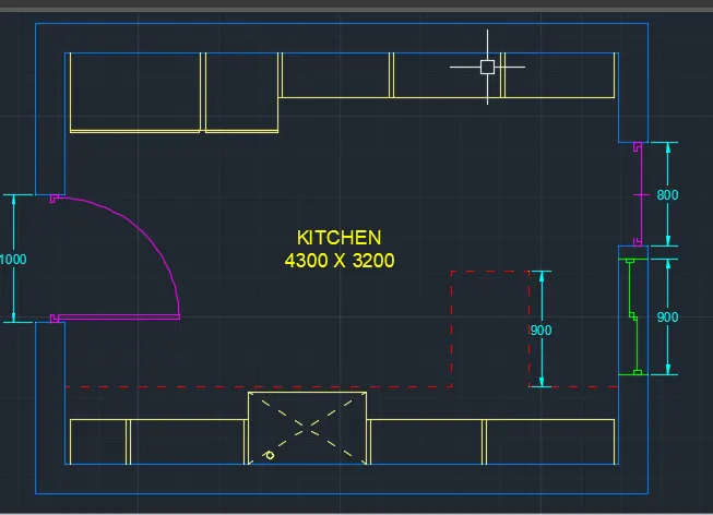
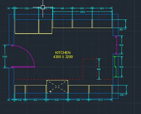
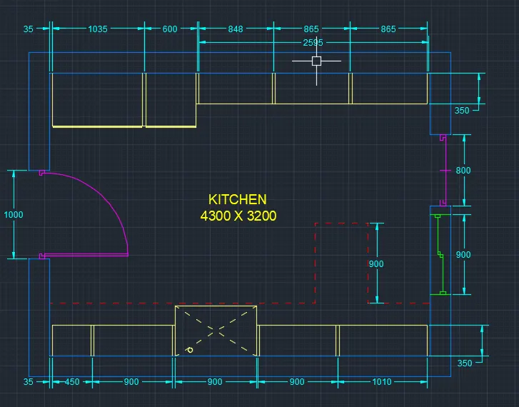
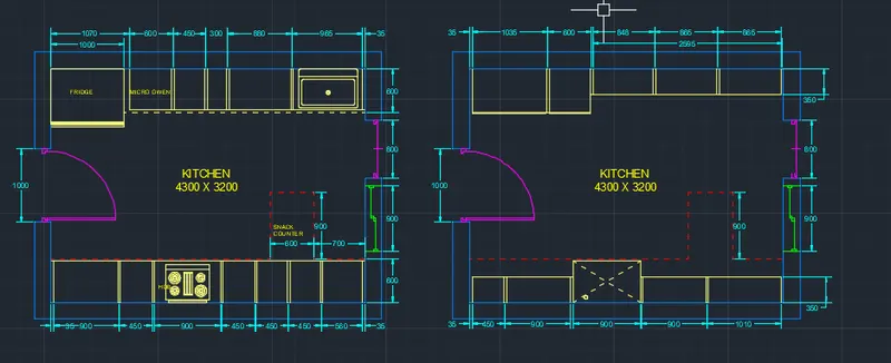
Q3. Create the Kitchen Layout as shown in the Figure below. Also, use proper dimension techniques to dimension the kitchen layout. Also, insert text wherever required. All dimensions are in mm.
AIM :
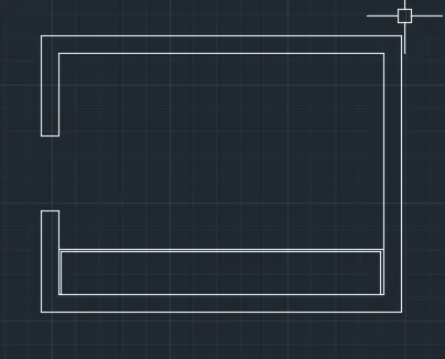
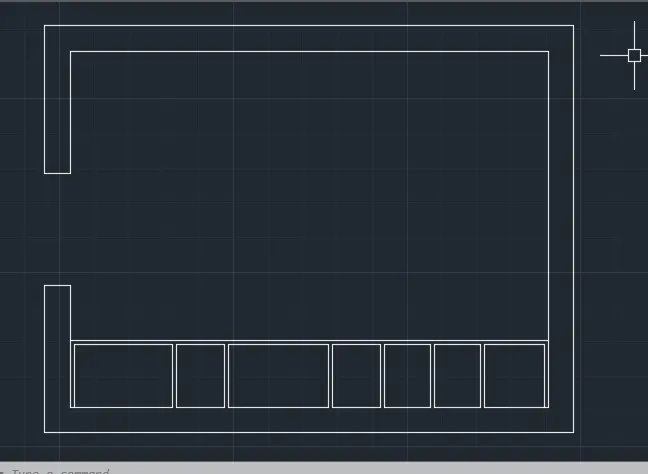
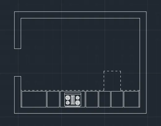
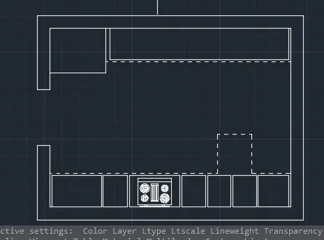
THE KITCHEN PLAN IS DRAWN WITH THE HELP OF THE FOLLOWING AUTOCAD TOOLS
PROCEDURE :
OPEN ATOCAD
CHENGE UNITS AS YOUR REQURED
Units command UN Enter chenge units asyour requred
next DIMSTYLE
Next limits
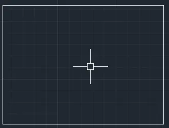
- THE OUTER EDGES OF THE KITCHEN PLAND ARE MARKED WITH THE HELP OF HORIZONTAL AND VERTICAL CONSTRUCTION LINES.
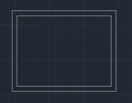
- AN OFFSET OF 230mm IS DRAWN TO MARK THE WALLS OF THE KITCHEN.
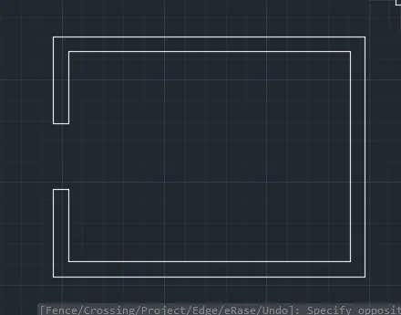
- THE COUNTERS IN THE KITCHEN IS DRAWN WITH OFFSET AGAIN AND THE REQUIRED SEMENTS ARE CREATED AS PER THE DIMENSIONS.
- THIS IS THEN COPIED TO CREATE THE TOP PART OF THE KITCHEN AREA AND THE COUTER REIONS ARE EDITED AS THE DIMESIONS.
- THE HATCHING IS PROVIDED WITH THE HELP OT HATCH COMMAND TO MARK THE WALL REGION.
- THE EXTRA AND UNWANTED LINES ARE TRIMMED AND DELETED LATER.

RESULT :
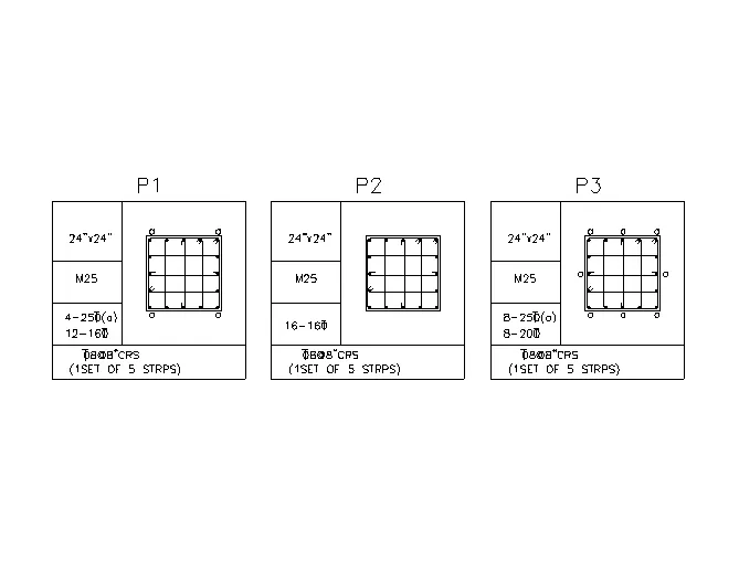
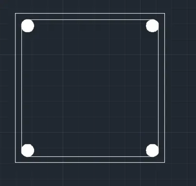
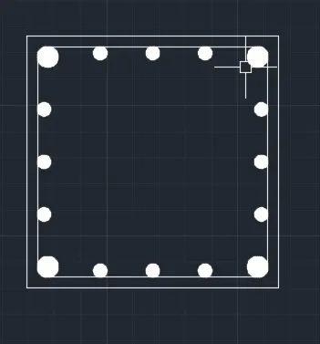
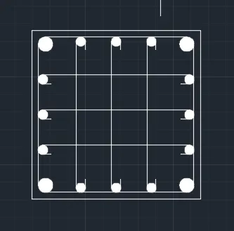
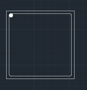
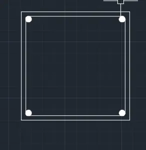
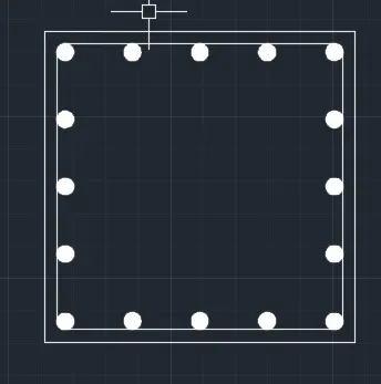
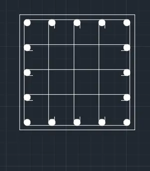
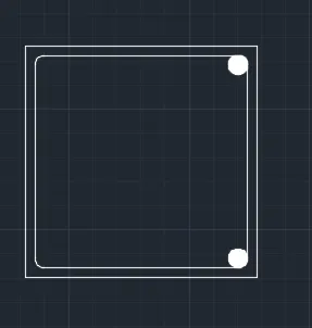
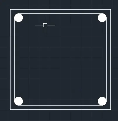
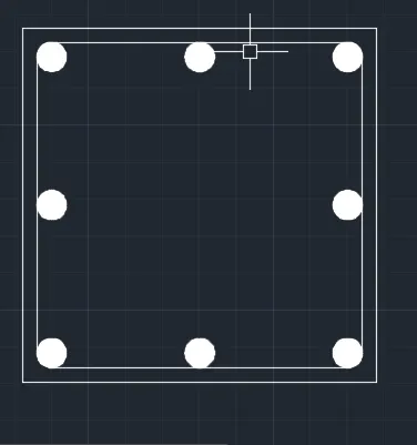
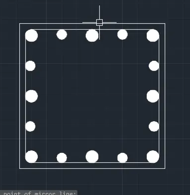
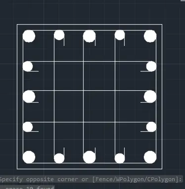
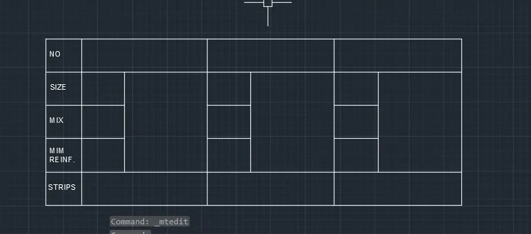
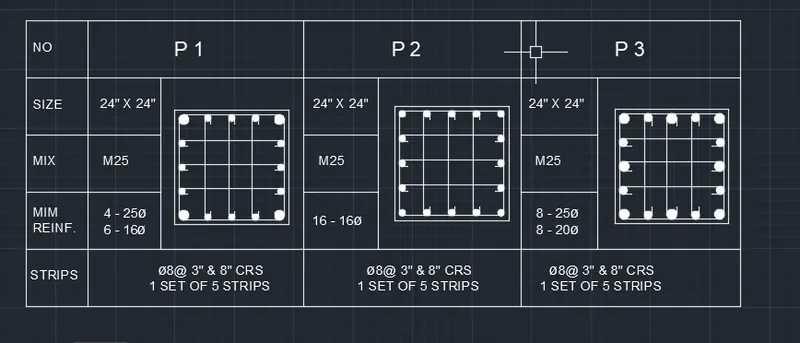
Q4. Sketch the column details as shown in Figure. Insert dimensions and text in the figure. Refer to the bar sizes from the schedule.
8mm ---- 0.31 Inches
25mm--- 1 inches
16mm—0.62 inches
AIM :
Sketch the column details as shown in Figure by useing AUTOCAD TOOL
PROCEDURE :
OPEN ATOCAD
CHENGE UNITS AS YOUR REQURED
Units command UN Enter chenge units asyour requred
next DIMSTYLE
Next limits
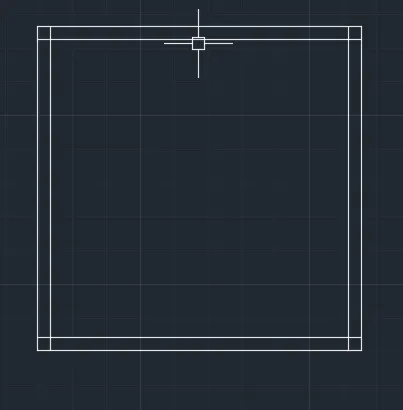
Command: L
LINE
Specify first point:
Specify next point or [Undo]: 24"
Specify next point or [Undo]: 24"
Specify next point or [Close/Undo]: 24"
Specify next point or [Close/Undo]: c
Command: O
OFFSET
Current settings: Erase source=No Layer=Source OFFSETGAPTYPE=0
Specify offset distance or [Through/Erase/Layer] <Through>: 0.984"
Select object to offset or [Exit/Undo] <Exit>:
Specify point on side to offset or [Exit/Multiple/Undo] <Exit>:
Select object to offset or [Exit/Undo] <Exit>:
Specify point on side to offset or [Exit/Multiple/Undo] <Exit>:
Select object to offset or [Exit/Undo] <Exit>:
Specify point on side to offset or [Exit/Multiple/Undo] <Exit>:
Select object to offset or [Exit/Undo] <Exit>:
Specify point on side to offset or [Exit/Multiple/Undo] <Exit>:
Select object to offset or [Exit/Undo] <Exit>: *Cancel*
Command: F
FILLET
Current settings: Mode = TRIM, Radius = 0'-0.00"
Select first object or [Undo/Polyline/Radius/Trim/Multiple]: R
Specify fillet radius <0'-0.00">: 0
Select first object or [Undo/Polyline/Radius/Trim/Multiple]: M
Select first object or [Undo/Polyline/Radius/Trim/Multiple]:
Select second object or shift-select to apply corner or [Radius]:
Select second object or shift-select to apply corner or [Radius]:
Select first object or [Undo/Polyline/Radius/Trim/Multiple]:
Select second object or shift-select to apply corner or [Radius]:
Select first object or [Undo/Polyline/Radius/Trim/Multiple]:
Select second object or shift-select to apply corner or [Radius]:
Select first object or [Undo/Polyline/Radius/Trim/Multiple]:
Select second object or shift-select to apply corner or [Radius]:
Select first object or [Undo/Polyline/Radius/Trim/Multiple]:
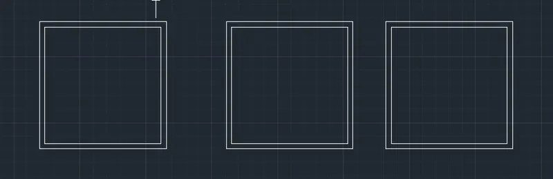
Command: CO
COPY
Select objects: Specify opposite corner: 8 found
Select objects:
Current settings: Copy mode = Multiple
Specify base point or [Displacement/mOde] <Displacement>:
Specify second point or [Array] <use first point as displacement>:
Specify second point or [Array/Exit/Undo] <Exit>:
Specify second point or [Array/Exit/Undo] <Exit>: *Cancel*
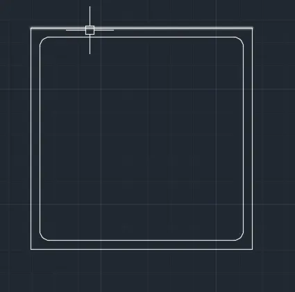
Command: F
FILLET
Current settings: Mode = TRIM, Radius = 0'-0.00"
Select first object or [Undo/Polyline/Radius/Trim/Multiple]: R
Specify fillet radius <0'-0.00">: 0.984"
Select first object or [Undo/Polyline/Radius/Trim/Multiple]:
Select second object or shift-select to apply corner or [Radius]:
Command: FILLET
Current settings: Mode = TRIM, Radius = 0'-0.98"
Select first object or [Undo/Polyline/Radius/Trim/Multiple]:
Select second object or shift-select to apply corner or [Radius]:
Command: FILLET
Current settings: Mode = TRIM, Radius = 0'-0.98"
Select first object or [Undo/Polyline/Radius/Trim/Multiple]:
Select second object or shift-select to apply corner or [Radius]:
Command: FILLET
Current settings: Mode = TRIM, Radius = 0'-0.98"
Select first object or [Undo/Polyline/Radius/Trim/Multiple]:
Select second object or shift-select to apply corner or [Radius]:
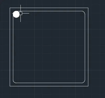
Command: C
CIRCLE
Specify center point for circle or [3P/2P/Ttr (tan tan radius)]:
Specify radius of circle or [Diameter]: 0.984"
Command: H
HATCH
Pick internal point or [Select objects/Undo/seTtings]: Selecting everything...
Selecting everything visible...
Analyzing the selected data...
Analyzing internal islands...
Pick internal point or [Select objects/Undo/seTtings]: *Cancel*
Command: MI
MIRROR 2 found
Specify first point of mirror line:
Specify second point of mirror line:
Erase source objects? [Yes/No] <No>:
Command: Specify opposite corner or [Fence/WPolygon/CPolygon]:
Command: MI
MIRROR 4 found
Specify first point of mirror line:
Specify second point of mirror line:
Erase source objects? [Yes/No] <No>:
Command: C
CIRCLE
Specify center point for circle or [3P/2P/Ttr (tan tan radius)]:
Specify radius of circle or [Diameter] <0'-0.98">: 0.629"
Command: H
HATCH
Pick internal point or [Select objects/Undo/seTtings]: Selecting everything...
Selecting everything visible...
Analyzing the selected data...
Analyzing internal islands...
Pick internal point or [Select objects/Undo/seTtings]:
Command: DIV
DIVIDE
Select object to divide:
Enter the number of segments or [Block]: 4
Command: DIVIDE
Select object to divide:
Enter the number of segments or [Block]: 4
Command: DIVIDE
Select object to divide:
Enter the number of segments or [Block]: 4
Command: DIVIDE
Select object to divide:
Enter the number of segments or [Block]: 4
Command: CO
COPY 2 found
Current settings: Copy mode = Multiple
Specify base point or [Displacement/mOde] <Displacement>:
Specify second point or [Array] <use first point as displacement>:
Specify second point or [Array/Exit/Undo] <Exit>:
Specify second point or [Array/Exit/Undo] <Exit>:
Specify second point or [Array/Exit/Undo] <Exit>: *Cancel*
Command: L
LINE
Specify first point:
Specify next point or [Undo]:
Specify next point or [Undo]: *Cancel*
Command:
Command:
Command: _arc
Specify start point of arc or [Center]:
Specify second point of arc or [Center/End]: _e
Specify end point of arc:
Specify center point of arc (hold Ctrl to switch direction) or [Angle/Direction/Radius]: _d
Specify tangent direction for the start point of arc (hold Ctrl to switch direction):
SAME AS
RESULT :
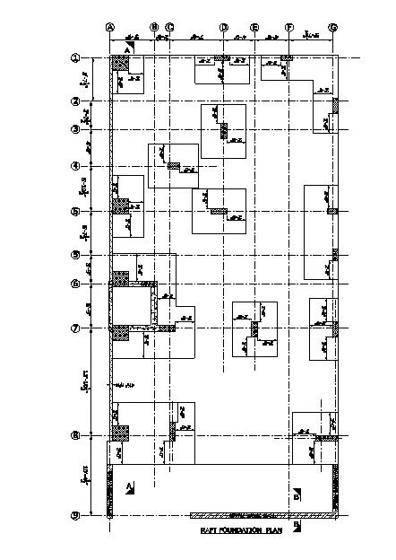
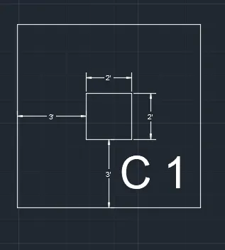
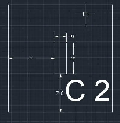
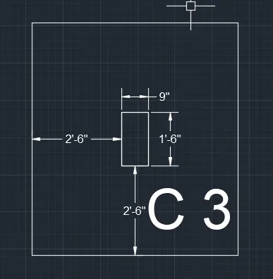
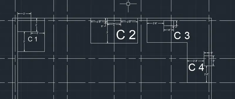
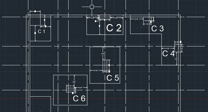
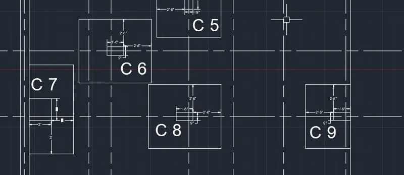
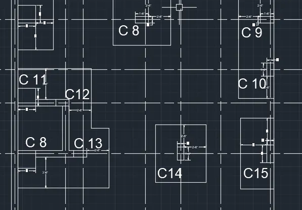
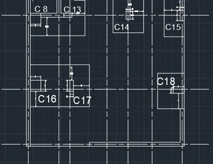
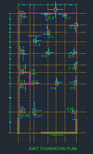
Q 5. Draw the Raft Layout as shown in the Figure. Assume the column size as per your knowledge. You can take the sizes as: 24”x24”, 9” x 24”, 9” x 18”, and 9’ x 24”. You can import the raft_foundation.pdf to ensure the missing dimensions.
AIM :
To Draw the Raft Layout as shown in the Figure by useing AUTOCAD Tool
PROCEDURE :
OPEN ATOCAD
CHENGE UNITS AS YOUR REQURED
Units command UN Enter chenge units asyour requred
next DIMSTYLE
Next limits
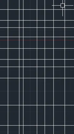
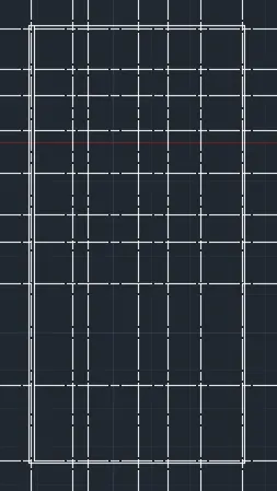
- GRID LINES AS PER THE MEASREMENTS ARE DRAWN IN ORDER TO LOCATE THE COLUMNS EXACTLY.
- THE COLUMNS ARE DRAWN AS PER THE SPECIFICATIONS MEASURING FROM THE GRID LINES.
- THE FOOTING FOR THE COLUMNS ARE DRAWN BY DRAWING RECTANGULARS OR THE MEASURED SIZES AND PLACING THEM OVER THE COLUMN AT THE REUIRED LOCATIONS.
- THE CATILEVER DISTANCES FROM THE COLUMN EDGES ARE ADJUSTED WHEREVER REQUIRED.
- THE EXTRA GRID LINES AND FOOTING LINES ARE TRIMMED AND DELETED.
- HATCHING IS PROVIDED TO MENTION THE WALL AND RETAINING WALL FORTHE RAFT.
RESULT :