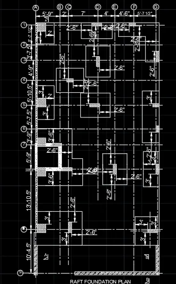
Creating a Wardrobe detailed drawing, Floor Plan, Kitchen Layout and Column Detail using AutoCad
1. WARDROBE DETAILED DRAWING
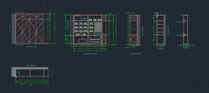
Aim: To draw the elevation and details of a wardrobe as shown in the figure above, in AutoCAD. Introduction: The Wardrobe detailed drawing is created in AutoCAD using primarily the Line tool and after sketching. the dimensions and text are provided with the use of layers. The procedure of drawing is explained in detail with diagrams of each step and the final result is given.
Procedure:
STEP 1
- Go to START MENU. select AutoCAD.
- In the Command line type in: STARTUP [ENTER]
- Enter new value of startup:1
- Go to Application Menu and select New
- In the Startup dialog box set Metric as the default settings.
- In the Advanced Setup and select the 'Decimal' unit of measurement and select precision as ' 0.00
- Set the limits by entering LIMITS in the Command tab. The lower-left corner is specified as 0,0; and the upper-right corner is specified as 8000,8000.
- Enter 'UNITS' command in the command tab.
- In the Drawing Units dialog box, select 'Decimal' in Type: ' 0' in Precision; and 'Millimeters' in Insertion scale.
- Click on 'OK.
STEP 2
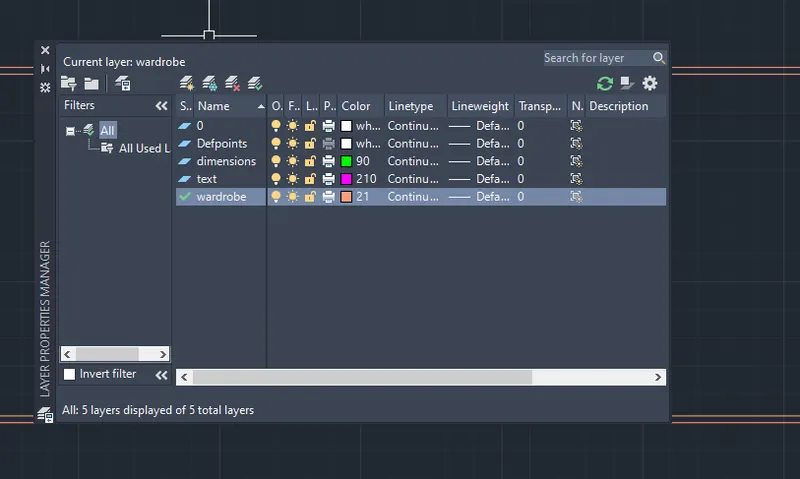
- Click on 'Layer Properties' in the Layer panel on the Ribbon.
- Click on 'New Layer' to create the following layers - Wardrobe, Dimension and Text.
- Specify different colors for the different layers and then close the Layer Properties Manager dialog box.
STEP 3 (PLAN)
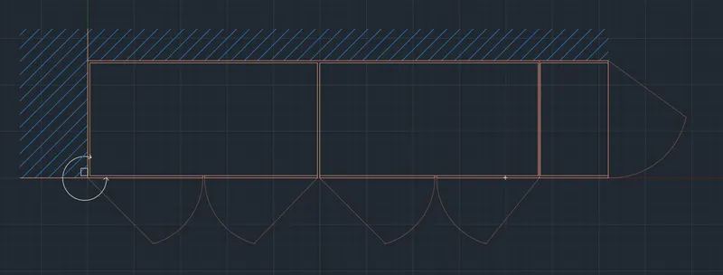
- Select the Wardrobe layer.
- Select the Line tool by entering 'LINE' command in the command tab.
- Specify the starting coordinate of point 1 as 0,0 in the command line.
- Specify the next coordinate of point 2 as @2800,0 in the command line.
- Specify the next coordinate of point 3 as @0,630 in the command line.
- Specify the next coordinate of point 4 as@-2800,0 in the command line.
- Click Close' on the command line.
- Select the Offset tool by entering OFFSET' command in the command tab.
- Enter 365 as offset distance in the command line.
- Select the right vertical edge of the object created before.
- Click on the inside of the object.
- Repeat offset, specify a distance of 1187, select the previous offsetted line and click towards the left of the selected line.
- Repeat offset, specify a distance of 12, select the outer edges and partition lines of the wardrobe individually and click on the inside of the selected line.
- Press 'Esc' to cancel the OFFSET command.
- Select the Line tool from the ribbon and draw a small box shaped (50X30) object at the bottom left corner of the wardrobe plan.
- Press 'Esc' to cancel the LINE command.
- Then the unwanted lines are Trimmed, and Erased to edit the drawing as per requirement.
- For the wardrobe doors, select PLINE tool and draw lines to represent the door swing.
- Next select the wardrobe doors, right click, select Properties and change the Transparency to 60.
- Draw a rectangle, using REC command, Specify the first point outside the top left corner of the wardrobe, and specify the second corner as the bottom right corner of the wardrobe.
- Select the Hatch tool, by entering H command, select JIS_LC_20 pattern, and set the hatch scale as per requirement, pick the point as the rectangle created earlier. Press Esc.
- Erase the outer rectangle.
- Selec the Arc tool from the ribbon, select the 3 Point option, and draw an arc as shown in the given diagram.
- Select the Line tool from the ribbon and draw arrows at the ends of the above arc.
- Press Esc.
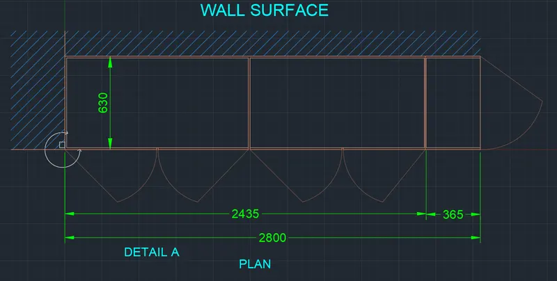
- Select the Dimensions and text layer.
- Enter 'DST command in the command tab to open the Dimension Style manager dialog box.
- Click on the Modify tab.
- Under the Symbols and Arrows option change the Arrow size to 30.
- Under the Text option change the Text height to 60.
- Click 0K. Then click on Set Current and Close the dialog box.
- Select the Dimension tool by entering 'DIM' in the command line.
- Select the first point and second point of the object to be measured, then drag the dimension line to the desired location. Repeat for all
- the objects to be measured.
- Enter 'MTEXT' command in the command line.
- Create the text box, scale the text to the desired size.
- Copy the text box to all desired locations.
- Enter ED in the command line, and edit the texts as required.
- Click Enter and press Esc.
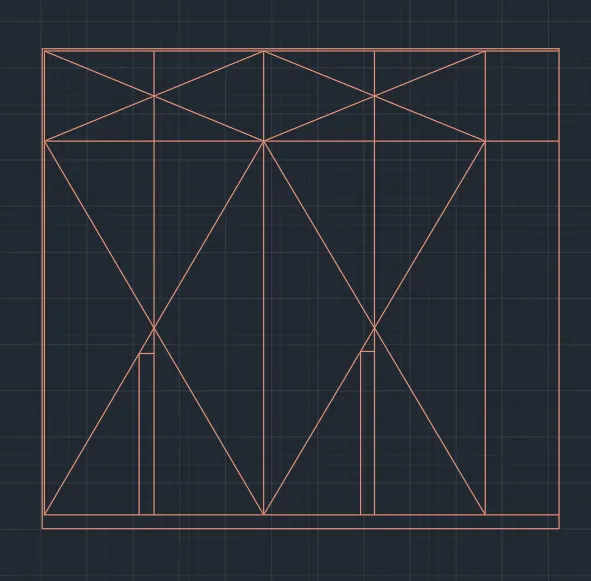
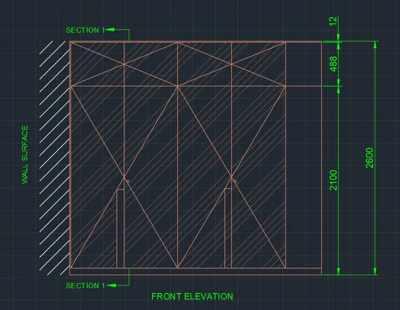
STEP 4 (FRONT ELEVATION)
- Select the Wardrobe layer.
- Select the Line tool by entering 'LINE' command in the command tab.
- Specify the start point.
- Point the cursor in the upward direction and enter a distance of 2600.
- Next point the cursor towards left and enter a distance of 2800.
- Point the cursor in the downward direction and enter a distance of 2600.
- Select Close in the command line.
- Select the Offset tool by entering OFFSET' command in the command tab.
- Specify a Offset of 12, Select the outer edges of the wardrobe and click on the inside to offset individually.
- Repeat offset, specify a distance of 100, select the bottom line (floor line) and click on the upwards.
- Repeat offset, specify a distance of 488, select the top outer edge of the wardrobe and click on the inside.
- Repeat offset, specify a distance of 365, select the right outer edge of the wardrobe and click on the inside.
- Select the Divide tool from the Ribbon, select the bottom horizontal line of the wardrobe remaining after the offset of 365, divide into 4 segments.
- Select the Line tool by entering 'LINE' command in the command tab.
- Draw lines from the three segment points to create the wardrobe doors.
- Press Esc.
- Erase the divide points.
- Then the unwanted lines are Trimmed, and Erased to edit the drawing as per requirement.
- Select the Polyline tool from the ribbon, and draw diagonal lines across the front face of the wardrobe as shown in the given image.
- Press Esc.
- Select the Line tool and draw the wardrobe handles as shown in the figure. Press Esc.
- Select the Circle tool from the ribbon, and specify the centre of circle, and specify radius of circle as 20.
- Enter CO in the command line, select the circle created earlier and copy it to the desired locations (to represent door knobs). Press Esc.
- Draw a rectangle, using REC command, Specify the first point outside the top left corner of the wardrobe, and specify the second corner as the bottom right corner of the wardrobe.
- Select the Hatch tool, by entering H command, select JIS_LC_20 pattern, and set the hatch scale as per requirement, pick the point as the rectangle created earlier. Press Esc.
- Erase the outer rectangle.
- Enter 'H' in the command line, select ANS134 pattern and pick point face of the wardrobe
- In the Hatch editor, increase the Transparency of the pattern to 60.
- Press Esc.
- Press Esc.
- Select the Dimensions and text layer.
- Select the Dimension tool by entering 'DIM' in the command line.
- Select the first point and second point of the object to be measured, then drag the dimension line to the desired location. Repeat for all the objects to be measured.
- Enter 'MTEXT' command in the command line.
- Create the text box, scale the text to the desired size.
- Copy the textbox to all desired locations.
- Enter ED in the command line, and edit the texts as required.
- Click Enter and press Esc.
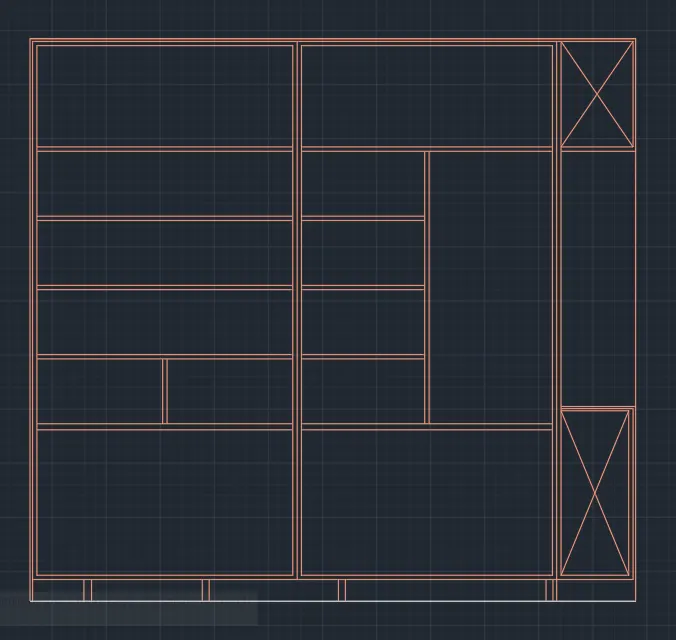
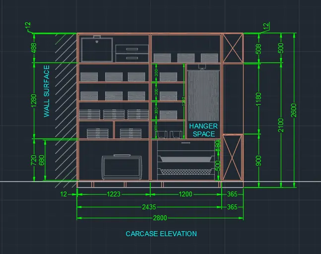
STEP 5 (CARCASE ELEVATION)
- Select the Wardrobe layer.
- Select the Line tool by entering 'LINE' command in the command tab.
- Specify the start point.
- Point the cursor in the upward direction and enter a distance of 2600.
- Next point the cursor towards left and enter a distance of 2800.
- Point the cursor in the downward direction and enter a distance of 2600.
- Select Close in the command line.
- Extend the bottom line on either side.
- Draw a rectangle, using REC command, Specify the first point outside the top left corner of the wardrobe, and specify the second corner as the bottom right corner of the wardrobe.
- Select the Hatch tool, by entering H command, select JIS_LC_20 pattern, and set the hatch scale as per requirement, pick the point as the rectangle created earlier. Press Esc.
- Erase the outer rectangle.
- Select the Offset tool by entering OFFSET' command in the command tab.
- Specify a Offset of 12, Select the outer edges of the wardrobe and click on the inside to offset individually.
- Repeat offset, specify a distance of 100, select the bottom line (floor line) and click on the upwards.
- Repeat offset, specify a distance of 1223, select the left inner edge of the wardrobe and click on the inside.
- Repeat offset, specify a distance of 1200, select the last offsetted line and click towards right.
- Repeat offset, specify a distance of 20, select the last offsetted lines and click to provide thickness of the wardrobe partions as per the given diagram.
- Repeat offset, specify a distance of 508, select the top edge of the wardrobe and click downwards.
- Repeat offset, specify a distance of 1260, select the last offsetted line and click downwards.
- Repeat offset, specify a distance of 20, provide thickness to the last two offsetted lines.
- Repeat offset, specify a distance of 300 select the last offsetted line and click downwards.
- Repeat offset, specify a distance of 20, prov'de thickness to the previous offsetted line.
- Repeat offset, specify a distance of 300, select the last offsetted line and click downwards.
- Repeat offset, specify a distance of 20, prov'de thickness to the previous offsetted line.
- Repeat offset, specify a distance of 300, select the last offsetted line and click downwards.
- Repeat offset, specify a distance of 20, provide thickness to the previous offsetted line.
- Repeat offset, specify a distance of 300, select the last offsetted line and click downwards.
- Repeat offset, specify a distance of 20, provide thickness to the previous offsetted line.
- Press Esc.
- Enter 'Tr' in the command prompt, click Enter twice and select the unwanted portion of lines.
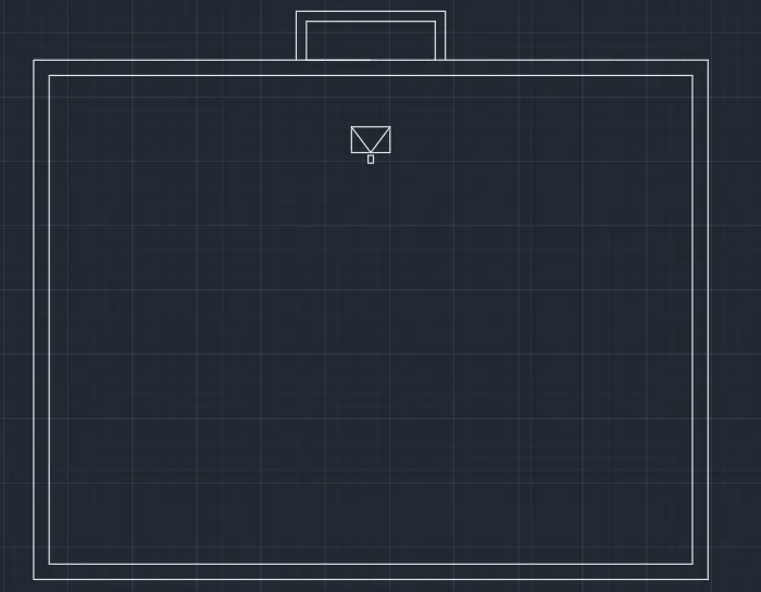
- To create the brief case, select the Rectangle tool by entering 'rec' command in the command tab.
- Specify a start point.
- Specify length of rectangle as 500 in the command line.
- Specify width of rectangle as 380 in the command line.
- Move the cursor upwards and click ENTER.
- Select the Offset tool by entering OFFSET' command in the command tab.
- Specify a Offset of 12, Select the outer edge, click on the inside of the rectangle to offset.
- Press Esc.
- Select the Line tool by entering 'LINE' command in the command tab.
- Draw lines to create the handle and lock of the brief case.
- Press Esc.
- Select the entire object, right click, go to Properties and change Transparency to 60.
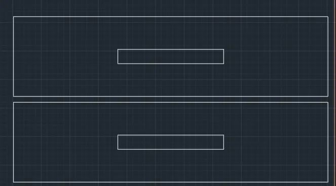
- To create the chest of drawers, select the Rectangle tool by entering 'rec' command in the command tab.
- Specify a start point.
- Select Dimensions option in the command line.
- Specify length of rectangle as 550 in the command line.
- Specify width of rectangle as 140 in the command line.
- Move the cursor upwards and click ENTER.
- Again enter 'rec' command in the command tab.
- Specify a start point inside the rectangle of dimension 550 x 140.
- Select Dimensions option in the command line.
- Specify length of rectangle as 185 in the command line.
- Specify width of rectangle as 25 in the command line.
- Move the cursor upwards and click ENTER.
- Enter CO command in the command prompt.
- Select the drawer image created just before.
- Specify a base point and copy it below the above top drawer.
- Press Esc.
- Select the entire object, right click, go to Properties and change Transparency to 60.
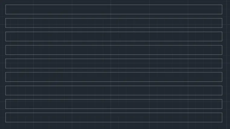
- To create the clothes, select the Rectangle tool by entering 'rec' command in the command tab.
- Specify a start point.
- Select Dimensions option in the command line.
- Specify length of rectangle as 280 in the command line.
- Specify width of rectangle as 12 in the command line.
- Move the cursor upwards and click ENTER.
- Enter CO command in the command prompt.
- Select the rectangle created just before.
- Specify base point as the bottom left corner of the rectangle.
- Click on Array option in the command prompt.
- Enter number of times to array as 9.
- Click on Fit option in the command line.
- Specify the second point as suitable.
- Press Esc.
- Again enter CO in the command line.
- Select the array of objects created earlier and copy them to all desired locations.
- Press Esc.
- Select the entire object, right click, go to Properties and change Transparency to 60.
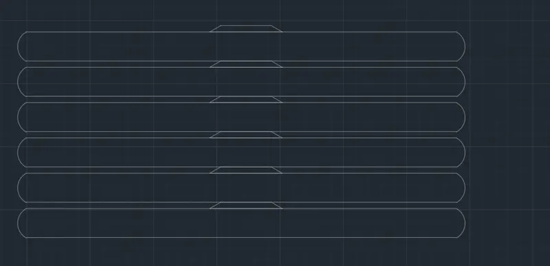
- To create the shirts, select the Rectangle tool by entering 'rec' command in the command tab.
- Specify a start point.
- Select Dimensions option in the command line.
- Specify length of rectangle as 340 in the command line.
- Specify width of rectangle as 23 in the command line.
- Move the cursor upwards and click ENTER.
- Select the Arc tool from the ribbon and draw arcs at both the ends.
- Trim the unwanted lines.
- Select the Line tool by entering 'LINE' command in the command tab.
- Draw lines to create the collar of the shirt.
- Press Esc.
- Enter CO command in the command prompt.
- Select the rectangle created just before.
- Specify base point as the bottom left corner of the rectangle.
- Click on Array option in the command prompt.
- Enter number of times to array as 6.
- Click on Fit option in the command line.
- Specify the second point as suitable.
- Press Esc.
- Again enter CO in the command line.
- Select the array of objects created earlier and copy them to all desired locations.
- Press Esc.
- Select the entire object, right click, go to Properties and change Transparency to 60.
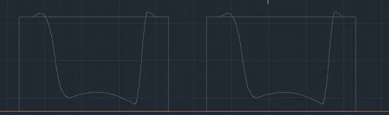
- To create the basket, select the Rectangle tool by entering 'rec' command in the command tab.
- Specify a start point.
- Select Dimensions option in the command line.
- Specify length of rectangle as 200 in the command line.
- Specify width of rectangle as 120 in the command line.
- Move the cursor upwards and click ENTER.
- Enter PLINE in the command prompt
- Draw a line to depict a piece of cloth in the box.
- Press Esc.
- Enter CO in the command line.
- Select the object created earlier and copy it to the desired location.
- Press Esc.
- Select the entire object, right click, go to Properties and change Transparency to 60.
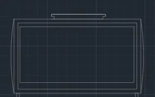
- To create the suitcase, select the Rectangle tool by entering 'rec' command in the command tab.
- Specify a start point.
- Select Dimensions option in the command line.
- Specify length of rectangle as 650 in the command line.
- Specify width of rectangle as 380 in the command line.
- Move the cursor upwards and click ENTER.
- Select the Offset tool by entering OFFSET' command in the command tab.
- Specify a Offset of 20, Select the outer edge, click on the inside of the rectangle to offset.
- Press Esc.
- Select the offsetted rectangle and click on the Explode tool on the ribbon.
- Press Esc.
- Select the Offset tool by entering OFFSET' command in the command tab.
- Specify a Offset distance of 20, select the top side of the rectangle, click on the inside of the rectangle to offset.
- Repeat offset, specify a Offset distance of 12, select the left and right sides of the rectangle individually, click on the inside of the
- rectangle to offset.
- Repeat offset, specify a Offset distance of 40, select the left and bottom line of the rectangle, click on the inside of the rectangle to
- Press Esc.
- Select the Line tool by entering 'LINE' command in the command tab.
- Draw the suitcase handle and support as shown in the given image.
- Press Esc.
- Select the Arc tool from the ribbon and draw arcs at both the ends.
- Enter CO in the command line.
- Select the object created earlier and copy it to the desired location.
- Press Esc.
- Select the entire object, right click, go to Properties and change Transparency to 60.
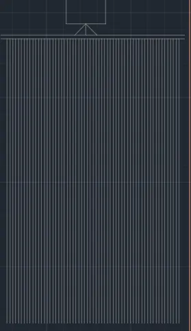
- Select the Line tool by entering 'LINE' command in the command tab.
- Draw lines to create the hanger rod.
- Press Esc.
- Again select the Line tool by entering 'LINE' command in the command tab.
- Draw a vertical line of length 880.
- Press Esc.
- Enter CO command in the command prompt.
- Select the line, specifi a base point, click on the Array option in the command line and enter number of items as 60.
- Then click on Fit and enter 8.
- Press Esc.
- Select the entire object, right click, go to Properties and change Transparency to 60.
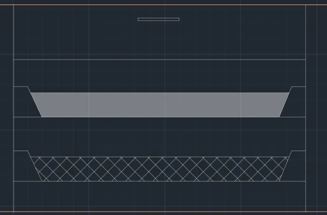
- Select the Line tool by entering 'LINE' command in the command tab.
- Draw two vertical lines of lenght 680 and three horizontal lines of length 900 to create the shelves.
- Press Esc.
- Enter PLINE in the command prompt
- Draw lines to draw the top portion of the shelves as shown in the figure.
- Press Esc.
- Select the Rectangle tool by entering 'REC' command in the command tab.
- Draw the handle of the top drawer.
- Press Esc.
- Select the Line tool by entering 'LINE' command in the command tab.
- Draw lines to create sections at the miidle rack.
- Press Esc.
- Enter 'H' in the command line, select SOLID pattern and pick point as the inside of the middle shelf.
- Enter 'H' in the command line, select ANS137 pattern and pick point as the inside of the bottom shelf.
- In the Hatch editor, increase the Transparency of the pattern to 60.
- Press Esc.
- Select the Dimensions and text layer.
- Select the Dimension tool by entering 'DIM' in the command line.
- Select the first point and second point of the object to be measured, then drag the dimension line to the desired location. Repeat for all
- the objects to be measured.
- Enter 'MTEXT' command in the command line.
- Create the text box, scale the text to the desired size.
- Copy the text box to all desired locations.
- Enter ED in the command line, and edit the texts as required.
- Click Enter and press Esc.
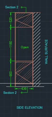
STEP 6 (SIDE ELEVATION)
- Select the Wardrobe layer.
- Select the Line tool by entering 'LINE' command in the command tab.
- Specify the start point.
- Point the cursor in the upward direction and enter a distance of 2600.
- Next point the cursor towards right and enter a distance of 630.
- Point the cursor in the downward direction and enter a distance of 2600.
- Select Close in the command line.
- Extend the top and bottom lines on either side.
- Select the Offset tool by entering OFFSET' command in the command tab.
- Specify a Offset distance of 12, select the top, left and right sides individually, click on the inside to offset.
- Repeat offset, specify a Offset distance of 100, select the bottom line of the rectangular figure, click on the inside of the rectangle to
- Repeat offset, specify a Offset distance of 800, select the last offsetted line of the figure, click on the inside of the rectangle to offset.
- Repeat offset, specify a Offset distance of 1180, select the last offsetted line of the figure, click on the inside of the rectangle to offset.
- Repeat offset, specify a Offset distance of 20, select the previous offsetted lines, click downwards to offset.
- Press Esc.
- Enter 'Tr' in the command prompt, click Enter twice and select the unwanted portion of lines.
- Press Esc.
- Rurn Ortho off.
- Select the Line tool by entering 'LINE' command in the command tab.
- Draw diagonal lines at the top and bottom sections as shown in the given diagram.
- Press Esc.
- Draw a rectangle, using REC command, Specify the first point outside the top left corner of the wardrobe, and specify the second corner as the bottom right corner of the wardrobe.
- Select the Hatch tool, by entering H command, select JIS_LC_20 pattern, and set the hatch scale as per requirement, pick the point as the rectangle created earlier. Press Esc.
- Erase the outer rectangle.
- Enter 'H' in the command line, select ANS134 pattern and pick point as the top and bottom portion of the side elevation.
- In the Hatch editor, increase the Transparency of the pattern to 60.
- Press Esc.
- Select the Dimensions and text layer.
- Select the Dimension tool by entering 'DIM' in the command line.
- Select the first point and second point of the object to be measured, then drag the dimension line to the desired location.
- Repeat for all the objects to be measured.
- Enter 'MTEXT' command in the command line.
- Create the text box, scale the text to the desired size.
- Copy the textbox to all desired locations.
- Enter ED in the command line, and edit the texts as required.
- Click Enter and press Esc.
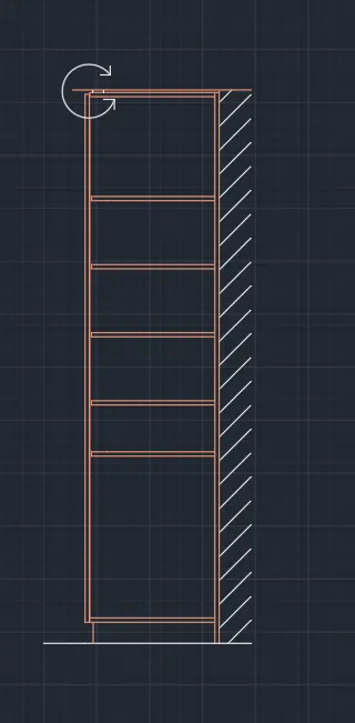
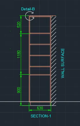
STEP 7 (SECTION-I)
- Select the Wardrobe layer.
- Select the Line tool by entering 'LINE' command in the command tab.
- Specify the start point.
- Point the cursor in the upward direction and enter a distance of 2600.
- Next point the cursor towards right and enter a distance of 630.
- Point the cursor in the downward direction and enter a distance of 2600.
- Select Close in the command line.
- Extend the top and bottom lines on either side.
- Select the Offset tool by entering OFFSET' command in the command tab.
- Specify a Offset distance of 12, select the top, left and right sides individually, click on the inside to offset.
- Repeat offset, specify a Offset distance of 100, select the bottom line of the rectangular figure, click on the inside of the rectangle to offset.
- Repeat offset, specify a Offset distance of 800, select the last offsetted line of the figure, click on the inside of the rectangle to offset.
- Repeat offset, specify a Offset distance of 300, select the last offsetted line, click upwards four times to offset.
- Repeat offset, specify a Offset distance of 20, select the previous offsetted lines individually, click downwards to offset and provide thickness to the shelves.
- Press Esc.
- Enter 'Tr' in the command prompt, click Enter twice and select the unwanted portion of lines to be trimmed.
- Press Esc.
- Draw a rectangle, using REC command, Specify the first point outside the top left corner of the wardrobe, and specify the second corner as the bottom right corner of the wardrobe.
- Select the Hatch tool, by entering H command, select JIS_LC_20 pattern, and set the hatch scale as per requirement, pick the point as the rectangle created earlier. Press Esc.
- Erase the outer rectangle.
- Press Esc.
- Selec the Arc tool from the ribbon, select the 3 Point option, and draw an arc as shown in the given diagram.
- Select the Line tool from the ribbon and draw arrows at the ends of the above arc.
- Press Esc.
- Select the Dimensions and text layer.
- Select the Dimension tool by entering 'DIM' in the command line.
- Select the first point and second point of the object to be measured, then drag the dimension line to the desired location. Repeat for all the objects to be measured.
- Select the Dimensions and text layer.
- Select the Dimension tool by entering 'DIM' in the command line.
- Select the first point and second point of the object to be measured, then drag the dimension line to the desired location. Repeat for all the objects to be measured.
- Enter 'MTEXT' command in the command line.
- Create the text box, scale the text to the desired size.
- Copy the text box to all desired locations.
- Enter ED in the command line, and edit the texts as required.
- Click Enter and press Esc.
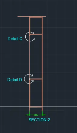
STEP 7 (SECTION-2)
- Select the Wardrobe layer.
- Select the Line tool by entering 'LINE' command in the command tab.
- Specify the start point.
- Point the cursor in the upward direction and enter a distance of 2600.
- Next point the cursor towards right and enter a distance of 365.
- Point the cursor in the downward direction and enter a distance of 2600.
- Select Close in the command line.
- Select the Offset tool by entering OFFSET' command in the command tab.
- Specify a Offset distance of 12, select the top, left and right sides individually, click on the inside to offset.
- Repeat offset, specify a Offset distance of 100, select the bottom line of the rectangular figure, click on the inside of the rectangle to offset.
- Repeat offset, specify a Offset distance of 800, select the last offsetted line of the figure, click on the inside of the rectangle to offset.
- Repeat offset, specify a Offset distance of 1180, select the last offsetted line of the figure, click on the inside of the rectangle to offset.
- Repeat offset, specify a Offset distance of 20, select the previous offsetted lines individually, click downwards to offset and privide thickness to the shelves.
- Press Esc.
- Enter 'Tr' in the command prompt, click Enter twice and select the unwanted portion of lines to be trimmed.
- Press Esc.
- Selec the Arc tool from the ribbon, select the 3 Point option, and draw an arc as shown in the given diagram.
- Select the Line tool from the ribbon and draw arrows at the ends of the above arc.
- Press Esc.
- Enter CO in the command line, select the direction circle created before and copy it to the desired location.
- Press Esc.
- Select the Dimensions and text layer.
- Select the Dimension tool by entering 'DIM' in the command line.
- Select the first point and second point of the object to be measured, then drag the dimension line to the desired location. Repeat for all the objects to be measured.
- Enter 'MTEXT' command in the command line.
- Create the text box, scale the text to the desired size.
- Copy the textbox to all desired locations.
- Enter ED in the command line, and edit the texts as required.
- Click Enter and press Esc.
RESULT
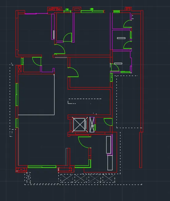
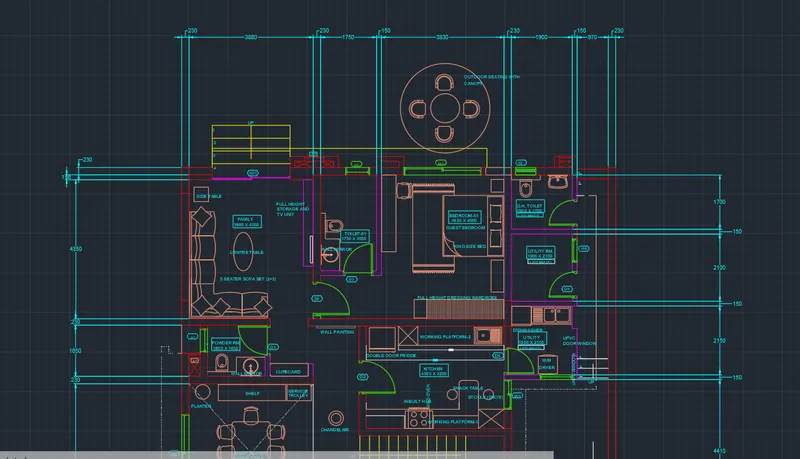
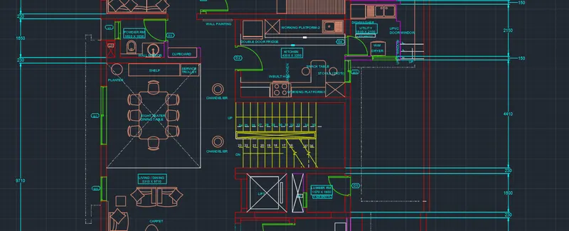
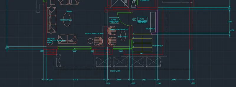
2.- FLOOR PLAN
Aim: To draw the floor plan as shown in the figure above, in AutoCAD.
Introduction:- The Floor plan is created in AutoCAD using primarily the Xline and Line tools and after sketching, the objects, dimensions and
texts are provided with the use of layers. The procedure of drawing is explained in detail with diagrams of each step and the final result is given.
Procedure:
STEP 1
- Go to START MENU, select AutoCAD
- In the Command line type in: STARTUP [ENTER]
- Enter new value of startup: 1
- Go to Application Menu and select New
- In the Startup dialog box set Metric as the default settings.
- In the Advanced Setup and select the 'Decimal' unit of measurement and select precision as'o
- Set the limits by entering LIMITS in the Command tab. The lower-left corner is specified as 0,0; and the upper-right corner is specified as 20000,20000.
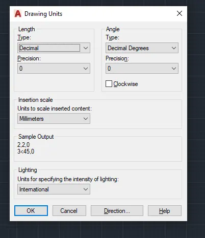
- Enter 'UNITS' command in the command tab.
- In the Drawing Units dialog box, select 'Decimal' in Type;'O' in Precision; and 'Millimeters' in Insertion scale.
- Click on 'OK:
STEP 2
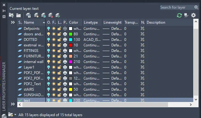
- Click on 'Layer Properties in the Layer panel on the Ribbon.
- Click on 'New Layer' to create the following layers - Doors and windows; External Wall; Internal Wall; Stairs; Furniture, Slab and Fittings;
and Dimension and Text. - Specify different colors for the different layers and then close the Layer Properties Manager dialog box.
STEP 3
- To begin drawing, select the Ext Wall layer as the default layer in the Layer panel.
- Select the Construction Line tool by entering 'XLINE' command in the command tab.
- Draw two lines, one vertical and the other horizontal, both intersecting at a point.
- Press Esc to cancel the XLINE.
- Select the Trim tool by entering 'TR' command in the command tab.
- Press ENTER.
- Select Edge option; and click on No Extend.
- Select the extruted lines.
- Press 'Esc' to cancel the TRIM command.
- Select the Offset tool by entering 'OFFSET' command in the command tab.
- As thickness of external wall is 230, enter 230 as offset distance in the command line.
- Select both the vertical and horizontal lines of the above drawing.
- Specify the next point on the desired side to offset.
- The vertical Xlines are offsetted to distances as per the given room dimensions and wall thickness.
- The horizontal Xlines are offsetted to distances as per the given room dimensions and wall thickness.
- Press 'Esc' to cancel the OFFSET command.
- The unwanted portion lines are trimmed off using the TRIM command.
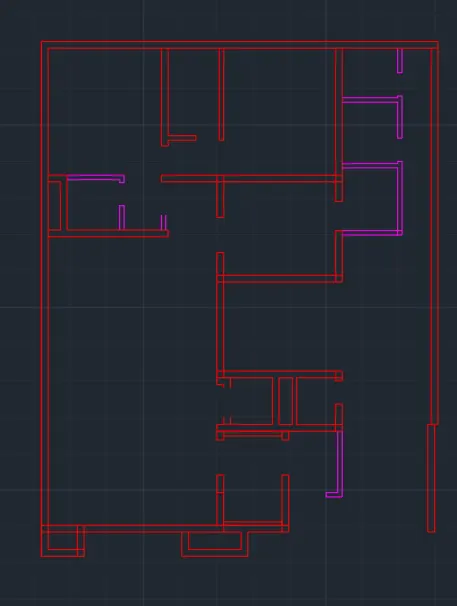
STEP 4
- Then the lines are Trimmed, Erased, Extended and/or Joined to edit the drawing as per requirement.
- Once all the external wall have been created, next the internal wall are drawn.
- Select the Int Wall layer as the default layer in the Layer panel.
- Select the Offset tool by entering OFFSET command in the command tab.
- Specify the offset distance, Select the line to offset and click on the direction we need the line in.
- While offsetting, the thickness of the internal walls is specified to be 150.
- Press "Esc' to cancel the OFFSET command.
- The new lines drawn are selected and assigned to the Int Wall layer.
- Then the lines are Trimmed, Erased, Extended and/or Joined to edit the drawing as per requirement.
STEP 5
- To draw doors, select the Doors and windows layer as the default layer in the Layer panel.
- Select the Line tool by entering 'LINE' command in the command tab.
- Draw doors at the specified positions.
- Door D1 is created at the entrance with a width of 1220.
- Press Esc to cancel the LINE command.
- Selet the Arc tool from the ribbon, choose the Start, End, Direction option, then draw an arc to represent the swing of the door by specifying the start, end and direction of the arc as suitable.
- Select the Line tool by entering ‘LINE' command in the command tab.
- Door D2 is created at the entry of bedroom and kitchen with a width of 1050.
- Press Esc to cancel the LINE command.
- Selet the Arc tool from the ribbon, choose the Start, End, Direction option, then draw an arc to represent the swing of the door by specifying the start, end and direction of the arc as suitable.
- Select the Line tool by entering 'LINE' command in the command tab.
- Door D3 is created at the entry of toilet and powder room with a width of 950.
- Press Esc to cancel the LINE command.
- Selet the Arc tool from the ribbon, choose the Start, End, Direction option, then draw an arc to represent the swing of the door by specifying the start, end and direction of the arc as suitable.
- Select the Line tool by entering 'LINE' command in the command tab.
- Door D4 is created at the entry of utility room with a width of 850.
- Press Esc to cancel the LINE command.
- Selet the Arc tool from the ribbon, choose the Start, End, Direction option, then draw an arc to represent the swing of the door by specifying the start, end and direction of the arc as suitable.
- Select the Line tool by entering ‘LINE' command in the command tab.
- Door D5 is created at the entry of the rest of the rooms with a width of 830.
- Press Esc to cancel the LINE command.
- Selet the Arc tool from the ribbon, choose the Start, End, Direction option, then draw an arc to represent the swing of the door by specifying the start, end and direction of the arc as suitable.
- To draw the windows, Select the Line tool by entering 'LINE' command in the command tab.
- Window WI is created with a width of 2430.
- Press Esc to cancel the LINE command.
- Select the Line tool by entering 'LINE' command in the command tab.
- Window W2 is created with a width of 3030.
- Press Esc to cancel the LINE command.
- Select the Line tool by entering 'LINE' command in the command tab.
- Window W3 is created with a width of 930.
- Press Esc to cancel the LINE command.
- Select the Line tool by entering 'LINE' command in the command tab.
- Window W9 is created with a width of 730.
- Press Esc to cancel the LINE command.
- Select the Line tool by entering 'LINE' command in the command tab.
- Window WIO is created with a width of 1730.
- Press Esc to cancel the LINE command.
- Select the Line tool by entering 'LINE' command in the command tab.
- Window VI is created with a width of 730.
- Press Esc to cancel the LINE command.
- Select the Line tool by entering 'LINE' command in the command tab.
- Window V2 is created with a width of 630.
- Press Esc to cancel the LINE command.
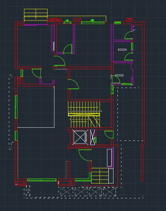
- For stair case drawing. select the Stairs layer as the default layer in the Layer panel.
- Select the Line tool by entering 'LINE' command in the command tab.
- Draw a line of length 1800 at the entry point of the building.
- Press Esc to cancel the LINE command. Select the Offset tool by entering 'OFFSET command in the command tab.
- Specify an offset distance of 300, then click on the desired side.
- Next keep selcting and offsetting the lines for desired number of times to form the stairs.
- Press Esc to cancel the OFFSET command.
- Select the Line tool by entering 'LINE' command in the command tab.
- Draw a line through the mid-point of the lines created previously to divide the stairs.
- Press Esc to cancel the LINE command.
- Again select the Line tool by entering 'LINE' command in the command tab.
- Press Esc to cancel the LINE command.
- Draw a line of length 2700 to create the central stairs.
- Press Esc to cancel the LINE command. Select the Offset tool by entering 'OFFSET command in the command tab.
- Specify an offset distance of 300, then click on the desired side.
- Next keep selcting and offsett'ng the lines for desired number of times to form the stairs.
- Press Esc to cancel the OFFSET command.
- Select the Line tool by entering 'LINE' command in the command tab.
- Draw a line through the mid-point of the lines created previously to divide the stairs.
- Press Esc to cancel the LINE command.
- Again select the Line tool by entering 'LINE' command in the command tab.
- Press Esc to cancel the LINE command.
- Draw a line of length 2700 to create the central stairs.
- Press Esc to cancel the LINE command. Select the Offset tool by entering 'OFFSET command in the command tab.
- Specify an offset distance of 300, then click on the desired side.
- Next keep selcting and offsett'ng the lines for desired number of times to form the stairs.
- Press Esc to cancel the OFFSET command.
- Select the Line tool by entering 'LINE' command in the command tab.
- Draw a line through the mid-point of the lines created previously to divide the stairs.
- Press Esc to cancel the LINE command.
- Again select the Line tool by entering 'LINE' command in the command tab.
- Draw lines showing the direction of the stairs.
- Select the Trim tool by entering TR' command in the command tab.
- Press ENTER.
- Select Edge option; and click on No Extend.
- Select the unwanted lines.
- Press 'Esc' to cancel the TRIM command.
STEP 6
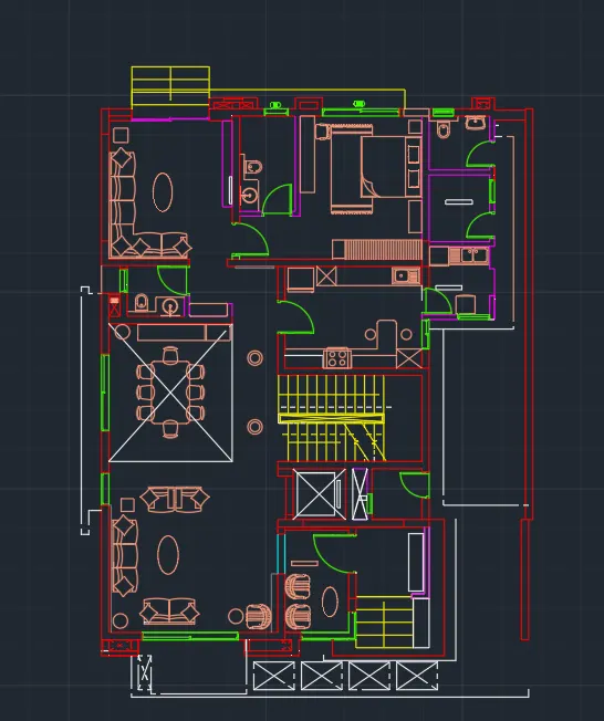
- Select the Furniture slab and fittings layer from the Layer panel.
- Click on the View tab.
- From the Palettes panel click on the DesignCentre icon.
- From the DESIGNCENTER dialog box select the required fixtures and appliances and copy them to the drawing sheet.
- Specify the base point, the Scale and position the fixtures and appliances according to the given drawing.
- Select the Line tool by entering 'LINE' command in the command tab.
- Draw lines in places where the dashed lines are in the drawing.
- Press Esc.
- Next select the lines, tight click, go to properties and specify the Line type as ISO dash space.
STEP 7
- Select the Furniture slab and fittings layer from the Layer panel.
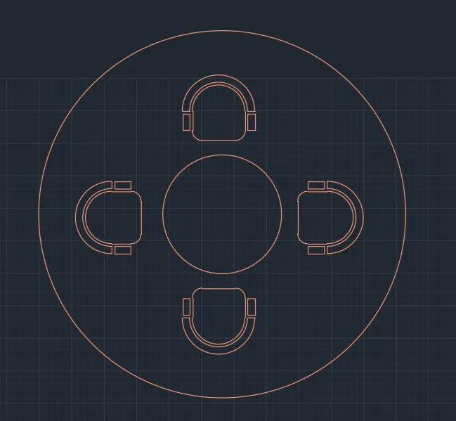
- Click on the Circle tool in the Ribbon.
- Select the Centre, Radius option from the drop down list.
- Specify the centre point of circle.
- Specify Radius of circle as 450.
- Again, click on the Circle tool in the Ribbon.
- Select the Centre, Radius option from the drop down list
- Specify the centre point as the centre of the previous circle.
- Specify Radius of circle as 1400.
- To draw the chair, first select the Rectangle tool by entering 'RECTANG command in the command tab.
- Specify the first point of the rectangle.
- Select Dimensions option in the command line.
- Specify length of rectangle as 350 in the command line.
- Specify width of rectangle as 150 in the command line.
- Move the cursor towards the upward and click ENTER.
- Select the Fillet tool, by entering 'F in the command tab.
- Selct the Radius option in the command line, and specify a radius of 50.
- Then select the lines to fillet the bottom two corners of the rectangle.
- Click on the Arc toot in the ribbon and select the Start, End, Angle option from the drop down list.
- Draw an arc by specifying the Start and End of the arc as the top corners of the rectangle created previously, and specify the angle as 90.
- Select the Offset tool by entering 'OFFSET command in the command tab.
- Specify an offset distance of 50.
- Select the arc created earlier, and then click on the outside of the arc and repeat again to create the chair handel.
- Press Esc to cancel the OFFSET command.
- Select the Line tool and draw lines to close the ends of the arcs.
- To draw the chair arms, select the Rectangle tool and draw rectangles of length 20 and width 50 at the location of the arm rests.
- Select the chair created and Move it to the desired location outside to the edge of the circle of radius 452.
- Click on the Array tool in the Modify panel, then selct the Polar array option.
- Select the chair created as the object to be copied and press ENTER.
- Specify the base point as the centre of the circles.
- Select the Items option in the command line.
- Specify the number of items as 4, and press ENTER.
STEP 8
- Select the Dimension and Text layer as the default layer in the Layer panel.
- Enter 'DST command in the command tab to open the Dimension Style Manager dialog box.
- Click on the Modify tab.
- Under the Lines option change the colour of the dimension and extension lines.
- Under the Symbols and Arrows option change the Arrow size to 100.
- Under the Text option change the Text height to 100.
- Click OK. Then click on Set Current and Close the dialog box.
- Select the Dimension tool by entering 'DIM' in the command line.
- Select the first point and second point of the object to be measured, then drag the dimension line to the desired location, Repeat for all the objects to be measured.
- Enter 'MTEXT command in the command line.
- Specify the start point of text as required.
- Scale the text to the desired size.
- Copy the text box to wherever necessary.
- Enter ED in the command promt and edit the text boxes as required.
- Click Enter and press Esc.
- Save the drawing.
RESULT
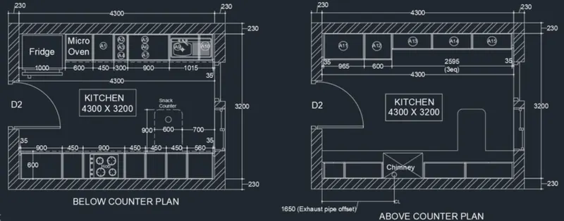
3.KITCHEN LAYOUT
Aim: To draw the kitchen layout as shown in the figure above, in AutoCAD.
Introduction: The kitchen layout is created in AutoCAD using primarily the Rectangle and Linc tools and after sketching. the objects, dimensions and texts are provided. The procedure of drawing is explained in detail with diagrams of each step and the final result is given.
Procedure:
STEP 1
- Go to START MENU, select AutoCAD.
- In the Command line type in: STARTUP [ENTER]
- Enter new value of startup:1
- Go to Application Menu and select New
- In the Startup dialog box set Metric as the default settings.
- In the Advanced Setup and select the 'Decimal' unit of measurement and select precision as 0
- Set the limits by entering LIMITS in the Command tab.
- The lower-left corner is specified as 0,0; and the upper-right corner is specified as 5000,5000.
- Enter 'UNITS' command in the command tab.
- In the Drawing Units dialog box, select 'Decimal' in Type: 0' in Precision; and 'Millimeters' in Insertion scale.
- Click on 'OK.
STEP 2 (BELOW COUNTER PLAN)
- Select the Rectangle tool by entering 'REC' command in the command tab.
- Specify the first point
- Select Dimensions option in the command line.
- Specify length of rectangle as 4760 in the command line.
- Specify width of rectangle as 3660 in the command line.
- Move the cursor towards the upward and click ENTER.
- Select the Offset tool by entering 'OFFSET command in the command tab.
- As thickness of external wall is 230, enter 230 as offset distance in the command line.
- Select both the rectangle created before.
- Click on the inside to offset.
- Press Esc.
STEP 3
- Select the Line tool by entering 'LINE' command in the command tab.
- Specify the start point
- Draw a line joining the inner edges of the kitchen wall, press Esc.
- Select the line, right click, go to properties and change the line type to ISO dash.
- Select the Rectangle tool by entering 'REC' command in the command tab.
- Specify the first point at the inner edge of the .
- Select Dimensions option in the command line.
- Specify length of rectangle as 35 in the command line.
- Specify width of rectangle as 50 in the command line.
- Move the cursor towards the upward and click ENTER.
- Select the Rectangle tool by entering 'REC' command in the command tab.
- Specify the first point at the inner edge of the .
- Select Dimensions option in the command line.
- Specify length of rectangle as 900 in the command line.
- Specify width of rectangle as 560 in the command line.
- Move the cursor towards the upward and click ENTER.
- Select the rectangle and click on the Explode icon in the Ribbon.
- Select the Offset tool by entering 'OFFSET command in the command tab.
- Specify offset distance as 20.
- Offset the top, right and left sides of the rectangle.
- Repeat offset, specify offset distance as 10.
- Offset the bottom edge of the rectangle
- Press Esc.
- Select the Rectangle tool by entering 'REC' command in the command tab.
- Specify the first point at the inner edge of the .
- Select Dimensions option in the command line.
- Specify length of rectangle as 450 in the command line.
- Specify width of rectangle as 560 in the command line.
- Move the cursor towards the upward and click ENTER.
- Select the rectangle and click on the Explode icon in the Ribbon.
- Select the Offset tool by entering 'OFFSET command in the command tab.
- Specify offset distance as 20.
- Offset the top, right and left sides of the rectangle.
- Repeat offset, specify offset distance as 10.
- Offset the bottom edge of the rectangle
- Press Esc.
- Select the Rectangle tool by entering 'REC' command in the command tab.
- Specify the first point at the inner edge of the .
- Select Dimensions option in the command line.
- Specify length of rectangle as 900 in the command line.
- Specify width of rectangle as 560 in the command line.
- Move the cursor towards the upward and click ENTER.
- Select the rectangle and click on the Explode icon in the Ribbon.
- Select the Offset tool by entering 'OFFSET command in the command tab.
- Specify offset distance as 20.
- Offset the top, right and left sides of the rectangle.
- Repeat offset, specify offset distance as 10.
- Offset the bottom edge of the rectangle
- Press Esc.
- Select the Rectangle tool by entering 'REC command in the command tab.
- Specify the first point at the inner edge of the .
- Select Dimensions option in the command line.
- Specify length of rectangle as 450 in the command line.
- Specify width of rectangle as 560 in the command line.
- Move the cursor towards the upward and click ENTER.
- Select the rectangle and click on the Explode icon in the Ribbon.
- Select the Offset tool by entering 'OFFSET command in the command tab.
- Specify offset distance as 20.
- Offset the top, right and left sides of the rectangle.
- Repeat offset, specify offset distance as 10.
- Offset the bottom edge of the rectangle
- Press Esc.
- Select the Rectangle tool by entering 'REC command in the command tab.
- Specify the first point at the inner edge of the .
- Select Dimensions option in the command line.
- Specify length of rectangle as 450 in the command line.
- Specify width of rectangle as 560 in the command line.
- Move the cursor towards the upward and click ENTER.
- Select the rectangle and click on the Explode icon in the Ribbon.
- Select the Offset tool by entering 'OFFSET command in the command tab.
- Specify offset distance as 20.
- Offset the top, right and left sides of the rectangle.
- Repeat offset, specify offset distance as 10.
- Offset the bottom edge of the rectangle
- Press Esc.
- Select the Rectangle tool by entering 'REC command in the command tab.
- Specify the first point at the inner edge of the .
- Select Dimensions option in the command line.
- Specify length of rectangle as 450 in the command line.
- Specify width of rectangle as 560 in the command line.
- Move the cursor towards the upward and click ENTER.
- Select the rectangle and click on the Explode icon in the Ribbon.
- Select the Offset tool by entering 'OFFSET command in the command tab.
- Specify offset distance as 20.
- Offset the top, right and left sides of the rectangle.
- Repeat offset, specify offset distance as 10.
- Offset the bottom edge of the rectangle
- Press Esc.
- Select the Rectangle tool by entering 'REC' command in the command tab.
- Specify the first point at the inner edge of the .
- Select Dimensions option in the command line.
- Specify length of rectangle as 450 in the command line.
- Specify width of rectangle as 560 in the command line.
- Move the cursor towards the upward and click ENTER.
- Select the rectangle and click on the Explode icon in the Ribbon.
- Select the Offset toot by entering 'OFFSET command in the command tab.
- Specify offset distance as 20.
- Offset the top, right and left sides of the rectangle.
- Repeat offset, specify offset distance as 10.
- Offset the bottom edge of the rectangle
- Press Esc.
- Select the Rectangle tool by entering 'REC' command in the command tab.
- Specify the first point at the inner edge of the . Select Dimensions option in the command line.
- Specify length of rectangle as 560 in the command line.
- Specify width of rectangle as 560 in the command line.
- Move the cursor towards the upward and click ENTER.
- Select the rectangle and click on the Explode icon in the Ribbon.
- Select the Offset tool by entering 'OFFSET command in the command tab.
- Specify offset distance as 20.
- Offset the top, right and left sides of the rectangle.
- Repeat offset, specify offset distance as 10.
- Offset the bottom edge of the rectangle
- Press Esc.
- Select the Trim tool by entering TR' command in the command tab.
- Press ENTER.
- Select Edge option; and click on No Extend.
- Trim the unwanted portion of lines.
- Press 'Esc' to cancel the TRIM command.
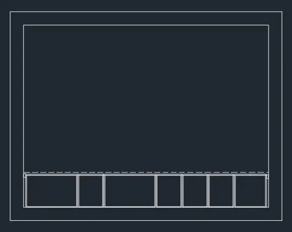
STEP 4
- Select the Line tool by entering 'LINE' command in the command tab.
- Specify the start point
- Draw a line joining the top inner edges of the kitchen wall, press Esc.
- Select the line, right click, go to properties and change the line type to ISO dash.
- Select the Rectangle tool by entering 'REC' command in the command tab.
- Specify the first point at the top right inner edge of the .
- Select Dimensions option in the command line.
- Specify length of rectangle as 35 in the command line.
- Specify width of rectangle as 50 in the command line.
- Move the cursor towards the upward and click ENTER.
- Select the Rectangle tool by entering 'REC' command in the command tab.
- Specify the first point at the inner edge of the .
- Select Dimensions option in the command line.
- Specify length of rectangle as 300 in the command line.
- Specify width of rectangle as 560 in the command line.
- Move the cursor towards the upward and click ENTER.
- Select the rectangle and click on the Explode icon in the Ribbon.
- Select the Offset tool by entering OFFSET command in the command tab.
- Specify offset distance as 20.
- Offset the bottom, right and left sides of the rectangle.
- Repeat offset command, specify offset distance as 10.
- Offset the top edge of the rectangle
- Press Esc.
- Select the Rectangle tool by entering 'REC' command in the command tab.
- Specify the first point at the inner edge of the .
- Select Dimensions option in the command line.
- Specify length of rectangle as 640 in the command line.
- Specify width of rectangle as 560 in the command line.
- Move the cursor towards the upward and click ENTER.
- Select the rectangle and click on the Explode icon in the Ribbon.
- Select the Offset tool by entering 'OFFSET command in the command tab.
- Specify offset distance as 20.
- Offset the bottom, right and left sides of the rectangle.
- Repeat offset, specify offset distance as 10.
- Offset the top edge of the rectangle
- Press Esc.
- Select the Rectangle tool by entering 'REC' command in the command tab.
- Specify the first point at the inner edge of the .
- Select Dimensions option in the command line.
- Specify length of rectangle as 900 in the command line.
- Specify width of rectangle as 560 in the command line.
- Move the cursor towards the upward and click ENTER.
- Select the rectangle and click on the Explode icon in the Ribbon.
- Select the Offset tool by entering 'OFFSET command in the command tab.
- Specify offset distance as 20.
- Offset the bottom, right and left sides of the rectangle.
- Repeat offset, specify offset distance as 10.
- Offset the top edge of the rectangle
- Press Esc.
- Select the Rectangle tool by entering 'REC' command in the command tab.
- Specify the first point at the inner edge of the .
- Select Dimensions option in the command line.
- Specify length of rectangle as 300 in the command line.
- Specify width of rectangle as 560 in the command line.
- Move the cursor towards the upward and click ENTER.
- Select the rectangle and click on the Explode icon in the Ribbon.
- Select the Offset tool by entering 'OFFSET command in the command tab.
- Specify offset distance as 20.
- Offset the bottom, right and left sides of the rectangle.
- Repeat offset, specify offset distance as 10.
- Offset the top edge of the rectangle
- Press Esc.
- Select the Rectangle tool by entering 'REC' command in the command tab.
- Specify the first point at the inner edge of the .
- Select Dimensions option in the command line.
- Specify length of rectangle as 450 in the command line.
- Specify width of rectangle as 560 in the command line.
- Move the cursor towards the upward and click ENTER.
- Select the rectangle and click on the Explode icon in the Ribbon.
- Select the Offset tool by entering 'OFFSET command in the command tab.
- Specify offset distance as 20.
- Offset the top, right and left sides of the rectangle.
- Repeat offset, specify offset distance as 10.
- Offset the bottom edge of the rectangle
- Press Esc.
- Select the Rectangle tool by entering 'REC' command in the command tab.
- Specify the first point at the inner edge of the .
- Select Dimensions option in the command line.
- Specify length of rectangle as 600 in the command line.
- Specify width of rectangle as 560 in the command line.
- Move the cursor towards the upward and click ENTER.
- Select the rectangle and click on the Explode icon in the Ribbon.
- Select the Offset toot by entering 'OFFSET command in the command tab.
- Specify offset distance as 20.
- Offset the bottom, right and left sides of the rectangle.
- Repeat offset, specify offset distance as 10.
- Offset the top edge of the rectangle
- Press Esc.
- Select the Trim tool by entering TR' command in the command tab.
- Press ENTER.
- Select Edge option; and click on No Extend.
- Trim the unwanted portion of lines.
- Press 'Esc' to cancel the TRIM command.
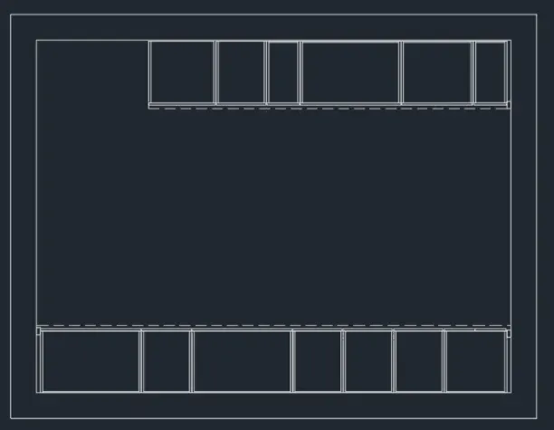
STEP 5
- Select the Line tool by entering 'LINE' command in the command tab.
- Specify the start point.
- Draw door at the specified positions.
- Door is created with a width of 1000.
- Press Esc to cancel the LINE command.
- Selet the Arc tool from the ribbon, choose the Start, End, Direction option, then draw an arc to represent the swing of the door by specifying the start, end and direction of the arc as suitable.
- Select the Line tool by entering 'LINE' command in the command tab.
- Draw the door frame.
- Press Esc.
- Select the Line tool by entering 'LINE' command in the command tab.
- Specify the start point.
- Draw window at the specified positions.
- Window is created with a width of 900.
- Press Esc to cancel the LINE command.
- Select the Line tool by entering 'LINE' command in the command tab.
- Draw the Window frame.
- Press Esc.
- Select the Line tool by entering 'LINE' command in the command tab.
- Create an opening of width 850.
- Draw the frame of the opening.
- Press Esc.
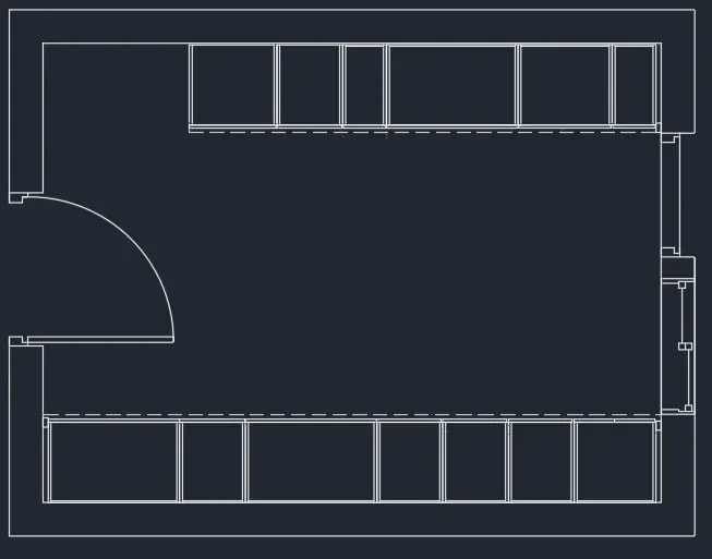
STEP 6
- Click on the View tab.
- From the Palettes panel click on the DesignCentre icon.
- Fron the DESIGNCENTER dialog box select the required fixtures and appliances and copy them to the drawing sheet.
- Specify the base point, the Scale and position the fixtures and appliances according to the given drawing.
- Select the Hatch tool, by entering H command, select ANS132 pattern, and set the hatch scale as per requirement, pick the point.
- Press Esc.
- Enter 'DST' command in the command tab to open the Dimension Style Manager dialog box.
- Click on the Modify tab.
- Under the Lines option change the colour of the dimension and extension lines.
- Under the Symbols and Arrows option change the Arrow size to 50, and Arrowhead as Dot small blank.
- Under the Text option change the Text height to 100.
- Click OK. Then click on Set Current and Close the dialog box.
- Select the Dimension tool by entering 'DIM' in the command line.
- Select the first point and second point of the object to be measured, then drag the dimension line to the desired location. Rcpcat for all the objects to be measured.
- Enter IMTEXT command in the command line.
- Specify the start point of text as required.
- Scale the text to the desired size.
- Copy the text box to wherever necessary.
- Enter ED in the command promt and edit the text boxes as required.
- Click Enter and press Esc.
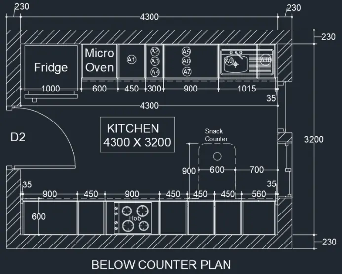
STEP 7 (ABOVE COUNTER PLAN)
- Select the Rectangle tool by entering 'REC command in the command tab
- Specify the first point.
- Select Dimensions option in the command line.
- Specify length of rectangle as 4760 in the command line.
- Specify width of rectangle as 3660 in the command line.
- Move the cursor towards the upward and click ENTER.
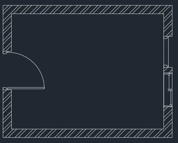
- Select the Offset tool by entering 'OFFSET' command in the command tab. As thickness of external wall is 230, enter 230 as offset distance in the command line.
- Select both the rectangle created before.
- Click on the inside to offset.
- Press Esc.
- Select the Line tool by entering 'LINE' command in the command tab.
- Specify the start point.
- Draw door at the specified positions.
- Door is created with a width of 1000.
- Press Esc to cancel the LINE command.
- Selet the Arc tool from the ribbon, choose the Start, End, Direction option, then draw an arc to represent the swing of the door by specifying the start, end and direction of the arc as suitable.
- Select the Line tool by entering 'LINE' command in the command tab.
- Draw the door frame.
- Press Esc.
- Select the Line tool by entering 'LINE' command in the command tab.
- Specify the start point.
- Draw window at the specified positions.
- Window is created with a width of 900.
- Press Esc to cancel the LINE command.
- Select the Line tool by entering 'LINE' command in the command tab.
- Draw the Window frame.
- Press Esc.
- Select the Line tool by entering 'LINE' command in the command tab.
- Create an opening of width 850.
- Draw the frame of the opening.
- Press Esc.
- Select the Hatch tool, by entering H command, select ANSI32 pattern, and set the hatch scale as per requirement, pick the point.
- Press Esc.
STEP 8
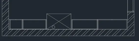
- Select the Line tool by entering 'LINE' command in the command tab.
- Specify the start point
- Draw a horizontal line of length 35 from the bottom left inner edge of the kitchen walL
- Press Esc.
- Select the Rectangle tool by entering 'REC' command in the command tab.
- Specify the first point at the inner edge of the .
- Select Dimensions option in the command line.
- Specify length of rectangle as 450 in the command line.
- Specify width of rectangle as 350 in the command line.
- Move the cursor towards the upward and click ENTER.
- Select the rectangle and click on the Explode icon in the Ribbon.
- Select the Offset tool by entering 'OFFSET command in the command tab.
- Specify offset distance as 20.
- Offset the top, right and left sides of the rectangle.
- Repeat offset, specify offset distance as 10.
- Offset the bottom edge of the rectangle
- Press Esc.
- Select the Rectangle tool by entering 'REC' command in the command tab.
- Specify the first point at the inner edge of the .
- Select Dimensions option in the command line.
- Specify length of rectangle as 900 in the command line.
- Specify width of rectangle as 350 in the command line.
- Move the cursor towards the upward and click ENTER.
- Select the rectangle and click on the Explode icon in the Ribbon.
- Select the Offset toot by entering 'OFFSET command in the command tab.
- Specify offset distance as 20.
- Offset the top, right and left sides of the rectangle.
- Repeat offset, specify offset distance as 10.
- Offset the bottom edge of the rectangle
- Press Esc.
- Leave a gap of 900 mm for the chimney.
- Select the Rectangle tool by entering 'REC' command in the command tab.
- Specify the first point at the inner edge of the .
- Select Dimensions option in the command line.
- Specify length of rectangle as 900 in the command line.
- Specify width of rectangle as 350 in the command line.
- Move the cursor towards the upward and click ENTER.
- Select the rectangle and click on the Explode icon in the Ribbon.
- Select the Offset tool by entering OFFSET command in the command tab.
- Specify offset distance as 20.
- Offset the top, right and left sides of the rectangle.
- Repeat offset, specify offset distance as 10.
- Offset the bottom edge of the rectangle
- Press Esc.
- Select the Rectangle tool by entering 'REC' command in the command tab.
- Specify the first point at the inner edge of the .
- Select Dimensions option in the command line.
- Specify length of rectangle as 1010 in the command line.
- Specify width of rectangle as 350 in the command line.
- Move the cursor towards the upward and click ENTER.
- Select the rectangle and click on the Explode icon in the Ribbon.
- Select the Offset tool by entering 'OFFSET command in the command tab.
- Specify offset distance as 20.
- Offset the top, right and left sides of the rectangle.
- Press Esc.
- To draw the chimney, select the Rectangle tool by entering 'REC' command in the command tab.
- Specify the first point at the inner edge of the .
- Select Dimensions option in the command line.
- Specify length of rectangle as 850 in the command line.
- Specify width of rectangle as 550 in the command line.
- Move the cursor towards the upward and click ENTER.
- Select the Line tool by entering 'LINE' command in the command tab.
- Draw diagonal lines connecting the opposite corners of the rectangle drawn before.
- Press Esc.
- Select the Circle tool by entering 'CIRCLE' command in the command tab.
- Draw a circle at the bottom left corner of the rectangle.
- Press Esc.
STEP 9
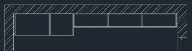
- Select the Line tool by entering 'LINE' command in the command tab.
- Specify the start point
- Draw a line joining the top inner edges of the kitchen wall, press Esc.
- Select the line, right click, go to properties and change the line type to ISO dash.
- Select the Rectangle tool by entering 'REC' command in the command tab.
- Specify the first point at the top right inner edge of the .
- Select Dimensions option in the command line.
- Specify length of rectangle as 35 in the command line.
- Specify width of rectangle as 50 in the command line.
- Move the cursor towards the upward and click ENTER.
- Select the Rectangle tool by entering 'REC' command in the command tab.
- Specify the first point at the inner edge of the .
- Select Dimensions option in the command line.
- Specify length of rectangle as 860 in the command line.
- Specify width of rectangle as 350 in the command line.
- Move the cursor towards the upward and click ENTER.
- Select the rectangle and click on the Explode icon in the Ribbon.
- Select the Offset toot by entering 'OFFSET command in the command tab.
- Specify offset distance as 20.
- Offset the bottom, right and left sides of the rectangle.
- Repeat offset command, specify offset distance as 10.
- Offset the top edge of the rectangle
- Press Esc.
- Select the Rectangle tool by entering 'REC' command in the command tab.
- Specify the first point at the inner edge of the .
- Select Dimensions option in the command line.
- Specify length of rectangle as 860 in the command line.
- Specify width of rectangle as 350 in the command line.
- Move the cursor towards the upward and click ENTER.
- Select the rectangle and click on the Explode icon in the Ribbon.
- Select the Offset tool by entering 'OFFSET command in the command tab.
- Specify offset distance as 20.
- Offset the bottom, right and left sides of the rectangle.
- Repeat offset, specify offset distance as 10.
- Offset the top edge of the rectangle
- Press Esc.
- Select the Rectangle tool by entering 'REC' command in the command tab.
- Specify the first point at the inner edge of the .
- Select Dimensions option in the command line.
- Specify length of rectangle as 860 in the command line.
- Specify width of rectangle as 350 in the command line.
- Move the cursor towards the upward and click ENTER.
- Select the rectangle and click on the Explode icon in the Ribbon.
- Select the Offset tool by entering OFFSET command in the command tab.
- Specify offset distance as 20.
- Offset the bottom, right and left sides of the rectangle.
- Repeat offset, specify offset distance as 10.
- Offset the top edge of the rectangle
- Press Esc.
- Select the Rectangle tool by entering 'REC' command in the command tab.
- Specify the first point at the inner edge of the .
- Select Dimensions option in the command line.
- Specify length of rectangle as 600 in the command line.
- Specify width of rectangle as 600 in the command line.
- Move the cursor towards the upward and click ENTER.
- Select the rectangle and click on the Explode icon in the Ribbon.
- Select the Offset tool by entering 'OFFSET command in the command tab.
- Specify offset distance as 20.
- Offset the top, right and left sides of the rectangle.
- Repeat offset, specify offset distance as 10.
- Offset the bottom edge of the rectangle
- Press Esc.
- Select the Rectangle tool by entering 'REC' command in the command tab.
- Specify the first point at the inner edge of the .
- Select Dimensions option in the command line.
- Specify length of rectangle as 965 in the command line.
- Specify width of rectangle as 600 in the command line.
- Move the cursor towards the upward and click ENTER.
- Select the rectangle and click on the Explode icon in the Ribbon.
- Select the Offset toot by entering 'OFFSET command in the command tab.
- Specify offset distance as 20.
- Offset the bottom, right and left sides of the rectangle.
- Repeat offset, specify offset distance as 10.
- Offset the top edge of the rectangle
- Press Esc.
- Select the Rectangle tool by entering 'REC' command in the command tab.
- Specify the first point at the inner edge of the .
- Select Dimensions option in the command line.
- Specify length of rectangle as 35 in the command line.
- Specify width of rectangle as 50 in the command line.
- Move the cursor towards the upward and click ENTER.
- Select the rectangle and click on the Explode icon in the Ribbon.
- Select the Offset tool by entering OFFSET command in the command tab.
- Specify offset distance as 20.
- Offset the bottom, right and left sides of the rectangle.
- Repeat offset, specify offset distance as 10.
- Offset the top edge of the rectangle
- Press Esc.
- Select the Trim tool by entering TR' command in the command tab.
- Press ENTER.
- Select Edge option; and click on No Extend.
- Trim the unwanted portion of lines.
- Press 'Esc' to cancel the TRIM command.
STEP 10
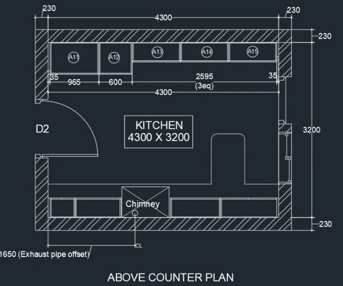
- Select the Dimension toot by entering 'DIM' in the command line.
- Select the first point and second point of the object to be measured. then drag the dimension line to the desired location. Repeat for all the objects to be measured.
- Enter 'MTEXT command in the command line.
- Specify the start point of text as required.
- Scale the text to the desired size.
- Copy the text box to wherever necessary.
- Enter ED in the command prompt and edit the text boxes as required.
- Click Enter and press Esc.
RESULT
COLUMN SECTIONS
Aim: To draw the column details as shown in the figure above, in AutoCAD. Introduction: The column details are created in AutoCAD using primarily the Rectangle and Line tools, and after sketching, the objects. dimensions and texts are provided. The procedure of drawing is explained in detail with diagrams of each step and the final result is given.
Procedure:
STEP I
- Go to START MENU, select AutoCAD
- In the Command line type in: STARTUP [ENTER]
- Enter new value of startup:1
- Go to Application Menu and select New
- In the 'Create New Drawing dialog box, we do the Advanced Setup and select the 'Engineering' unit of measurement and select precision as' 0'-0.0"
- Set the limits by entering LIMITS in the Command tab The lower-left corner is specified as 0'0.0",0'0.0": and the upper-right corner is specified as 100'-0.0'1,1001-0.0".
- Enter 'UNITS' command in the command tab.
- In the Drawing Units dialog box, select 'Engineering' in Type;' 0'-0.0— in Precision; and 'Inches' in Insertion scale.
- Click on 'OK'.
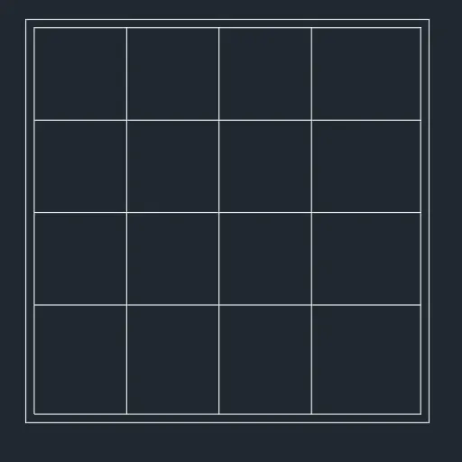
a) PI STEP 2
- Select the Rectangle tool by entering 'REG command in the command tab.
- Specify the first point.
- Select Dimensions option in the command line.
- Specify length of rectangle as 24" in the command line.
- Specify width of rectangle as 24" in the command line.
- Move the cursor towards the upward and click ENTER.
- Select the Offset tool by entering 'OFFSET' command in the command tab.
- Enter 0.5" as offset distance in the command line.
- Select the rectangle created before.
- Click on the inside to offset.
- Press Esc.
- Select the rectangle and click on the Explode icon in the Ribbon.
- Select the Offset tool by entering 'OFFSET' command in the command tab.
- Specify offset distance as 5.5".
- Offset the top and left sides of the above offsetted rectangle thrice.
- Press Esc.
STEP 3
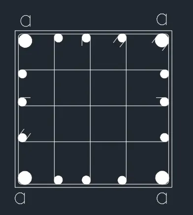
- Select the Circle tool by entering 'C' command in the command tab, specify the centre of the circle.
- Specify radius as 0.62"(representing bars of 16 mm dia.).
- Again select the circle tool and draw a circle of radius 1" (representing bars of 25 mm dia.).
- the Hatch tool, by entering H command, select Solid pattern, and pick point inside the circle.
- Press Esc.
- Enter 'CO' command in the command line.
- Select the circle of 'radius 0.62" and copy it to all desired locations do the same for the circle of radius 1"
- Select the fillet toot by entering 'F' in the command line. S
- pecify a radius of 0.5".
- Fillet all the corners of the inner rectangle after exploding it.
- Select the Line tool by entering 'LINE' command in the command tab.
- Draw lines to define the stirrups.
- Press 'Esc' to cancel the Line tool.
- Next enter the 'MTEXT command and type the letter 'a to highlight the bars of diameter 25 mm.
- Click Enter and press Esc.
STEP 4
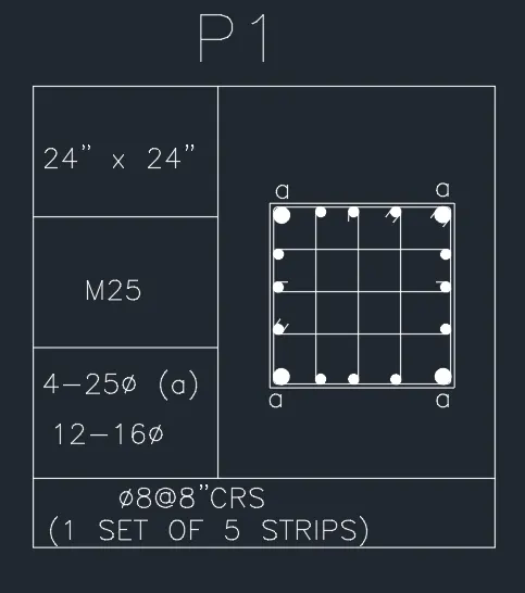
- Select the Rectangle tool by entering 'REC' command in the command tab.
- Specify the first point
- Select Dimensions option in the command line.
- Specify length of rectangle as 5' in the command line.
- Specify width of rectangle as 5' in the command line.
- Move the cursor towards the upward and click ENTER.
- Select the rectangle and click on the Explode icon in the Ribbon.
- Select the Offset tool by entering 'OFFSET command in the command tab.
- Specify offset distance as 1'5".
- Select the top edge of the rectangle and Offset it thrice.
- Press Esc.
- Select the Offset tool by entering 'OFFSET command in the command tab.
- Specify offset distance as 2'.
- Select the left edge of the rectangle and Offset it once.
- Press Esc.
- Select the Trim tool by entering TR' command in the command tab.
- Press ENTER.
- Select Edge option; and click on No Extend.
- Select the unwanted lines to trim.
- Press 'Esc' to cancel the TRIM command.
- Enter 'ST command in the command tab to open the Text Style dialog box.
- Select the Font Name as romans.shx; Text Height as 8".
- Enter 'MTEXT command in the command line.
- draw the text box and type in the desided information.
- Copy the text box to wherever necessary.
- Enter ED in the command prompt and edit the text boxes as required.
- Click Enter and press Esc.
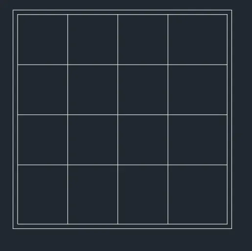
b) P2 STEP 5
- Select the Rectangle tool by entering 'REC' command in the command tab.
- Specify the first point
- Select Dimensions option in the command line.
- Specify length of rectangle as 24" in the command line.
- Specify width of rectangle as 24" in the command line.
- Move the cursor towards the upward and click ENTER.
- Select the Offset tool by entering 'OFFSET command in the command tab.
- Enter 0.5" as offset distance in the command line.
- Select the rectangle created before.
- Click on the inside to offset.
- Press Esc.
- Select the rectangle and click on the Explode icon in the Ribbon.
- Select the Offset tool by entering 'OFFSET command in the command tab.
- Specify offset distance as 5.5".
- Offset the top and left sides of the above offsetted rectangle thrice.
- Press Esc.
STEP 6
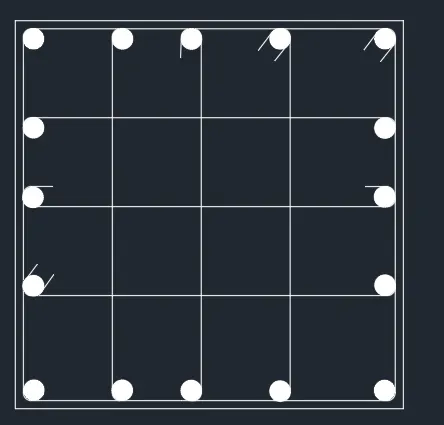
- Select the Circle tool by entering 'C' command in the command tab, specify the centre of the circle.
- Specify radius as 0.62"(representing bars of 16 mm dia.).
- Select the Hatch tool, by entering H command, select Solid pattern, and pick point inside the circle.
- Press Esc.
- Enter 'CO' command in the command line.
- Select the circle of 'radius 0.62" and copy it to all desired locations.
- Select the fillet tool by entering 'F' in the command line.
- Specify a radius of 0.5".
- Fillet all the corners of the inner rectangle after exploding it.
- Select the Line tool by entering 'LINE' command in the command tab.
- Draw lines to define the stirrups.
- Press 'Esc' to cancel the Line tool.
STEP 7
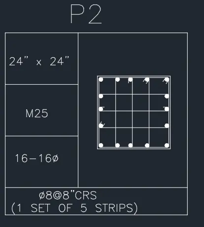
- Select the Rectangle tool by entering 'REG command in the command tab.
- Specify the first point.
- Select Dimensions option in the command line.
- Specify length of rectangle as 5' in the command line.
- Specify width of rectangle as 5' in the command line.
- Move the cursor towards the upward and click ENTER.
- Select the rectangle and click on the Explode icon in the Ribbon.
- Select the Offset tool by entering 'OFFSET' command in the command tab.
- Specify offset distance as 1'5".
- Select the top edge of the rectangle and Offset it thrice.
- Press Esc. • Select the Offset tool by entering 'OFFSET' command in the command tab.
- Specify offset distance as 2'.
- Select the left edge of the rectangle and Offset it once.
- Press Esc.
- Select the Trim tool by entering TR command in the command tab
- Press ENTER.
- Select Edge option; and click on No Extend.
- Select the unwanted lines to trim.
- Press 'Esc' to cancel the TRIM command.
- Enter 'MTEXr command in the command line.
- draw the text box and type in the desided information.
- Copy the text box to wherever necessary.
- Enter ED in the command prompt and edit the text boxes as required.
- Click Enter and press Esc.
c) P3
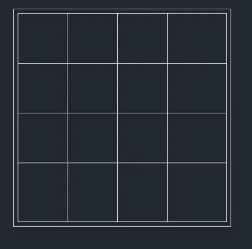
STEP 8
- Select the Rectangle tool
- by entering 'REC' command in the command tab.
- Specify the first point
- Select Dimensions option in the command line.
- Specify length of rectangle as 24" in the command line.
- Specify width of rectangle as 24" in the command line.
- Move the cursor towards the upward and click ENTER.
- Select the Offset tool by entering 'OFFSET command in the command tab.
- Enter 0.5" as offset distance in the command line.
- Select the rectangle created before.
- Click on the inside to offset.
- Press Esc.
- Select the rectangle and click on the Explode icon in the Ribbon.
- Select the Offset toot by entering 'OFFSET command in the command tab.
- Specify offset distance as 5.5".
- Offset the top and left sides of the above offsetted rectangle thrice.
- Press Esc.
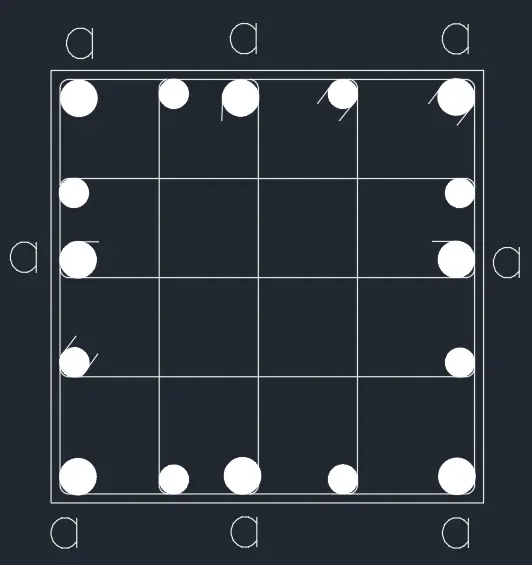
STEP 9
- Select the Circle tool by entering C. command in the command tab, specify the centre of the circle.
- Specify radius as 0.8"(representing bars of 20 mm dia.).
- Again select the circle tool and draw a circle of radius 1" (representing bars of 25 mm dia.).
- Select the Hatch tool, by entering H command, select Solid pattern, and pick point inside the circle.
- Press Esc.
- Enter 'CO' command in the command line.
- Select the circle of radius 0.8" and copy it to all desired locations do the same for the circle of radius 1"
- Select the fillet tool by entering 'F' in the command line.
- Specify a radius of 0.5".
- Fillet all the corners of the inner rectangle after exploding it.
- Select the Line tool by entering 'LINE' command in the command tab.
- Draw ones to define the stirrups.
- Press 'Esc' to cancel the Line toot.
- Next enter the 'MTEXT command and type the letter 'a' to highlight the bars of diameter 25 mm.
- Click Enter and press Esc.
STEP 10
- Select the Rectangle tool by entering 'REG command in the command tab.
- Specify the first point.
- Select Dimensions option in the command line.
- Specify length of rectangle as 5' in the command line.
- Specify width of rectangle as 5' in the command line.
- Move the cursor towards the upward and click ENTER.
- Select the rectangle and click on the Explode icon in the Ribbon.
- Select the Offset tool by entering 'OFFSET' command in the command tab.
- Specify offset distance as I'S".
- Select the top edge of the rectangle and Offset it thrice.
- Press Esc.
- Select the Offset tool by entering OFFSET' command in the command tab.
- Specify offset distance as 2'.
- Select the left edge of the rectangle and Offset it once.
- Press Esc.
- Select the Trim tool by entering IR* command in the command tab
- Press ENTER.
- Select Edge option; and click on No Extend.
- Select the unwanted lines to trim.
- Press 'Esc' to cancel the TRIM command.
- Enter 'MTEXr command in the command line.
- draw the text box and type in the desided information.
- Copy the text box to wherever necessary.
- Enter ED in the command prompt and edit the text boxes as required.
- Click Enter and press Esc.
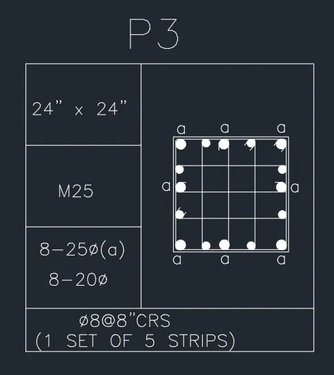
RESULT
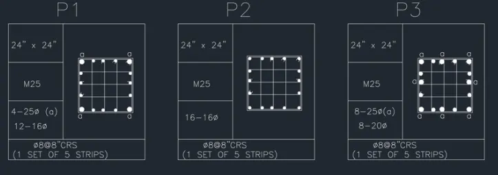
5.RAFT LAYOUT
Aim: To draw the raft layout as shown in the figure above, in AutoCAD. Introduction: The raft layout is created in AutoCAD using primarily the Line tool, and after sketching, the objects, dimensions and texts are provided. The procedure of drawing is explained in detail with diagrams of each step and the final result is given.
Procedure:
STEP 1
- Go to START MENU, select AutoCAD
- In the Command line type in: STARTUP [ENTER] Enter new value of startup:1
- Go to Application Menu and select New
- In the 'Create New Drawing dialog box, we do the Advanced Setup and select the 'Architectural' unit of measurement and select precision as' 0'-O 1/2"
- Set the limits by entering LIMITS in the Command tab. The lower-left corner is specified as 0'0.0'1,0'0.0% and the upper-right corner is specified as 100'-0.0“,1001-0.0“.
- Enter 'UNITS' command in the command tab.
- In the Drawing Units dialog box, select 'Architectural' in Type;' 0'-O 1/2"' in Precision; and 'Inches' in Insertion scale.
- Click on 'OK
STEP 2
- Click on 'Layer Properties' in the Layer panel on the Ribbon.
- Click on 'New Layer to create the following layers - Raft and Dimension and Text
- Specify different colors for the different layers and then close the Layer Properties Manager dialog box.
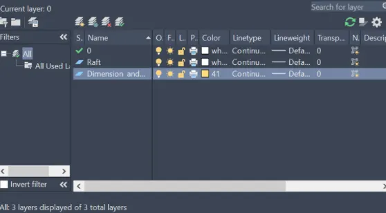
STEP 3
- Select the raft layer.
- Select the Line tool by entering 'LINE command in the command tab.
- Keep Ortho on.
- Specify the start point.
- Pointing the cursor in upward direction enter the following values consecutively -10'4 1/2", 13' 101/2", 5' 9", 3' 9", 5' 71/2", 5' 101/2", 4' 9", 3' 71/2", and 5'71/2"
- Pointing the cursor towards right hand direction enter the following values consecutively- 5'9", TO", 7'0", 4'0", 4'6". and 5'71/2".
- Turn on polar tracking and complete the rectangular figure.
- Press Esc.
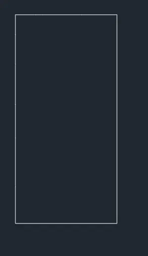
STEP 4
- Select the Offset tool by entering 'OFFSET command in the command tab.
- Specify offset distance as 6'7W.
- Select and offset the bottom line of the above rectangle.
- Press Esc.
- Select the Offset tool by entering 'OFFSET command in the command tab.
- Specify offset distance as 4W.
- Select and offset the boundary lines whereever required to provide wall thickness .
- Press Esc.
- Select the Trim tool by entering TR' command in the command tab.
- Press ENTER.
- Select Edge option; and click on No Extend.
- Select the unwanted lines to trim.
- Press 'Esc' to cancel the TRIM command.
- Select the Offset tool by entering 'OFFSET command in the command tab.
- Select the bottom line of the rectangle and offset it to the following distances - 10'41/2", 13'10 1/2", 5'9", 3'9", 5'7 1/2" , 5' 10 1/2", 4'9", 3'7 1/2", and 5' 7 1/2".
- Select the right hand edge of the rectangle and offset it to the following distances - 5' 7 1/2" , 4'6", 4'0", 7' 0", 2'0", and 5'9".
- Select the layout lines of the raft, right click, go to properties and change the line type to ISO long dash short dash.
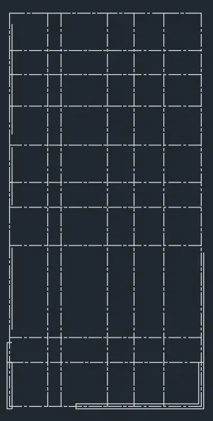
STEP 5
- Select the Line tool by entering 'LINE' command in the command tab.
- Keep Ortho on.
- Specify the start point.
- Draw footing of size 11' x 8'.
- Press Esc.
- Select the Offset tool by entering 'OFFSET' command in the command tab.
- Specify offset distance as 3'.
- Select the bottom edge of the rectangle and click upwards.
- Select the top edge of the rectangle and click downdards.
- Select the left edge of the rectangle, specify offset distance as 2' and click inside.
- Press Esc.
- Select the Trim tool by entering TR command in the command tab
- Press ENTER.
- Select Edge option; and click on No Extend.
- Select the unwanted lines to trim.
- Press 'Esc' to cancel the TRIM command.
- Select the Offset tool by entering 'OFFSET' command in the command tab.
- Specify offset distance as 2'6".
- Select the top edge of the rectangle and click downdards.
- Offset the previous offsetted line again to the same distance.
- Select the right edge of the rectangle and click inside.
- Select the previous offsetted line, specify offset distance as 9" and click towards left.
- Press Esc.
- Select the Trim tool by entering IR' command in the command tab
- Press ENTER.
- Select Edge option; and click on No Extend.
- Select the unwanted lines to trim.
- Press 'Esc' to cancel the TRIM command.
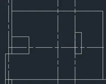
- Select the Line tool by entering 'LINE' command in the command tab.
- Keep Ortho on.
- Specify the start point.
- Draw footing of size 5'7.5" x 6'9".
- Press Esc.
- Select the Offset tool by entering 'OFFSET command in the command tab.
- Specify offset distance as 3'.
- Select the bottom edge of the rectangle and click upwards.
- Select the top edge of the rectangle and click downdards.
- Select the left edge of the rectangle and click inside.
- Press Esc.
- Select the Trim tool by entering TR command in the command tab
- Press ENTER.
- Select Edge option; and click on No Extend.
- Select the unwanted lines to trim.
- Press 'Esc' to cancel the TRIM command.
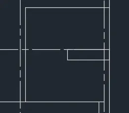
- Select the Line tool by entering 'LINE' command in the command tab.
- Specify the start point
- Enter the length of 11' in the command One towards +ve x-axis.
- Enter the length of 6'9" in the command line towards -ve y-axis.
- Enter the length of 2'4.5" in the command line towards -ye x-axis.
- Enter the length of 6'9" in the command line towards +e y-axis.
- Enter the length 8'3" in the command One towards -ve x-axis.
- Click 'Close on the command line.
- Select the Offset tool by entering OFFSET command in the command tab.
- Specify offset distance as 3'6".
- Select the bottom edge and click upwards.
- Select the top edge and click downdards.
- Press Esc.
- Select the Offset tool by entering 'OFFSET command in the command tab.
- Specify offset distance as 2'6".
- Select the bottom left edge and click inside.
- Select the top left edge and click inside.
- Press Esc.
- Select the Offset toot by entering 'OFFSET command in the command tab.
- Specify offset distance as 2'.
- Create offsets
- Press Esc.
- Select the Offset tool by entering 'OFFSET command in the command tab.
- Specify offset distance as 9".
- Create offsets
- Press Esc.
- Select the Trim tool by entering TR command in the command tab.
- Press ENTER.
- Select Edge option; and click on No Extend.
- Select the unwanted lines to trim.
- Press 'Esc' to cancel the TRIM command.
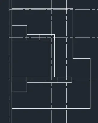
- Select the Line tool by entering 'LINE' command in the command tab.
- Keep Ortho on.
- Specify the start point
- Draw footing of size 5'9" x 7
- Press Esc.
- Select the Offset toot by entering 'OFFSET command in the command tab.
- Specify offset distance as 2'6".
- Select the bottom edge of the rectangle and click upwards.
- Select the top edge of the rectangle and click downdards.
- Select the left edge of the rectangle and click inside.
- Select the right edge of the rectangle and click inside.
- Press Esc.
- Select the Trim toot by entering TR' command in the command tab.
- Press ENTER.
- Select Edge option; and click on No Extend.
- Select the unwanted lines to trim.
- Press 'Esc' to cancel the TRIM command.
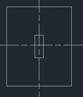
- Select the Line tool by entering 'LINE' command in the command tab.
- Keep Ortho on.
- Specify the start point.
- Draw footing of size 3'9" x 8'
- Press Esc.
- Select the Offset tool by entering 'OFFSET' command in the command tab.
- Specify offset distance as 3'.
- Select the bottom edge of the rectangle and click upwards.
- Select the top edge of the rectangle and click downdards.
- Select the left edge of the rectangle and click inside.
- Press Esc.
- Select the Trim tool by entering TR' command in the command tab.
- Press ENTER.
- Select Edge option: and click on No Extend.
- Select the unwanted lines to trim.
- Press 'Esc' to cancel the TRIM command.
- Select the Line tool by entering 'LINE' command in the command tab.
- Keep Ortho on.
- Specify the start point.
- Draw footing of size 4' x 8'.
- Press Esc.
- Select the Offset tool by entering 'OFFSET' command in the command tab.
- Specify offset distance as 3'.
- Select the bottom edge of the rectangle and click upwards.
- Select the top edge of the rectangle and click downdards.
- Press Esc.
- Select the Offset tool by entering 'OFFSET' command in the command tab.
- Specify offset distance as 2'.
- Select the right edge of the rectangle and click inside.
- Press Esc.
- Select the Trim tool by entering TR' command in the command tab.
- Press ENTER.
- Select Edge option: and click on No Extend.
- Select the unwanted lines to trim.
- Press 'Esc' to cancel the TRIM command.
- Select the Line tool by entering 'LINE' command in the command tab.
- Keep Ortho on.
- Specify the start point.
- Draw footing of size 7' x 5'9"
- Press Esc.
- Select the Offset tool by entering 'OFFSET command in the command tab.
- Specify offset distance as 2'6".
- Select the bottom edge of the rectangle and click upwards.
- Select the top edge of the rectangle and click downdards.
- Select the left edge of the rectangle and click inside.
- Select the right edge of the rectangle and click inside.
- Press Esc.
- Select the Trim tool by entering TR command in the command tab
- Press ENTER.
- Select Edge option; and click on No Extend.
- Select the unwanted lines to trim.
- Press 'Esc' to cancel the TRIM command.
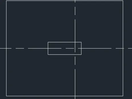
- Select the Line tool by entering 'LINE' command in the command tab.
- Keep Ortho on.
- Specify the start point.
- Draw footing of size 4'6" x 12'3".
- Press Esc.
- Select the Offset tool by entering 'OFFSET' command in the command tab.
- Specify offset distance as 3'.
- Select the top edge of the rectangle and click downdards.
- Select the previous offsetted line, specify offset distance as 9" and click downwards.
- Select the right edge of the rectangle, specify offset distance as 1'6" and click inside.
- Press Esc.
- Select the Trim tool by entering TR command in the command tab
- Press ENTER.
- Select Edge option; and click on No Extend.
- Select the unwanted lines to trim.
- Press 'Esc' to cancel the TRIM command.
- Select the Offset tool by entering 'OFFSET' command in the command tab.
- Specify offset distance as 2'6".
- Select the bottom edge of the rectangle and click downdards.
- Select thcprcvious offsetted line, specify offset distance as 1'6" and click downwards.
- Select the right edge of the rectangle specify offset distance as 9" and click towards left.
- Press Esc.
- Select the Trim tool by entering TR command in the command tab
- Press ENTER.
- Select Edge option; and click on No Extend.
- Select the unwanted lines to trim.
- Press 'Esc' to cancel the TRIM command.
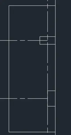
- Select the Line tool by entering 'LINE' command in the command tab.
- Keep Ortho on.
- Specify the start point.
- Draw footing of size 6'6" x 5'9" .
- Press Esc.
- Select the Offset tool by entering 'OFFSET' command in the command tab.
- Specify offset distance as 2'6".
- Select the bottom edge of the rectangle and click upwards.
- Select the top edge of the rectangle and click downdards.
- Select the left edge of the rectangle and click inside.
- Select the right edge of the rectangle and click inside.
- Press Esc.
- Select the Trim tool by entering TR command in the command tab
- Press ENTER.
- Select Edge option; and click on No Extend.
- Select the unwanted lines to trim.
- Press 'Esc' to cancel the TRIM command.
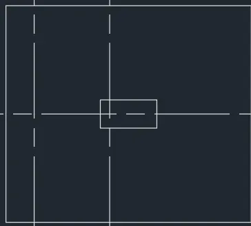
- Select the Line tool by entering 'LINE' command in the command tab.
- Keep Ortho on.
- Specify the start point.
- Draw footing of size 5'9" x 7'
- Press Esc.
- Select the Offset tool by entering OFFSET command in the command tab.
- Specify offset distance as 2'6".
- Select the bottom edge of the rectangle and click upwards.
- Select the top edge of the rectangle and click downdards.
- Select the left edge of the rectangle and click inside.
- Select the right edge of the rectangle and click inside.
- Press Esc.
- Select the Trim tool by entering TR command in the command tab
- Press ENTER.
- Select Edge option; and click on No Extend.
- Select the unwanted lines to trim.
- Press 'Esc' to cancel the TRIM command.
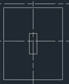
- Select the Line tool by entering 'LINE' command in the command tab.
- Specify the start point
- Enter the length of 3'3" in the command line towards -ve x-axis.
- Enter the length of 6'10.5" in the command line towards +ve y-axis.
- Enter the length of 6'9" in the command line towards -ve x-axis.
- Enter the length of 3'3" in the command One towards +ve y-axis.
- Enter the length 10' in the command One towards +ve x-axis.
- Click 'Close on the command line.
- Select the Offset tool by entering 'OFFSET command in the command tab.
- Specify offset distance as 2'6".
- Select the bottom edge and click upwards.
- Select the bottom left edge and click inside.
- Press Esc.
- Select the Offset tool by entering 'OFFSET command in the command tab.
- Specify offset distance as 2'.
- Create offset.
- Press Esc.
- Select the Trim tool by entering TR command in the command tab.
- Press ENTER.
- Select Edge option and click on No Extend.
- Select the unwanted lines to trim.
- Press 'Esc' to cancel the TRIM command.
- Select the Offset tool by entering 'OFFSET command in the command tab.
- Specify offset distance as 2'6".
- Select the bottom One and click upwards.
- Select the top left edge and click inside.
- Select theprevious offsetted line, specify offset distance as 1'6" and click towards right.
- Press Esc.
- Select the Trim tool by entering TR' command in the command tab.
- Press ENTER.
- Select Edge option; and click on No Extend.
- Select the unwanted lines to trim.
- Press 'Esc' to cancel the TRIM command.
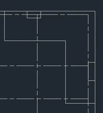
- Select the Line tool by entering 'LINE' command in the command tab.
- Keep Ortho on.
- Specify the start point.
- Draw footing of size 7' x 3'9".
- Press Esc.
- Select the Offset tool by entering 'OFFSET' command in the command tab.
- Specify offset distance as 3'.
- Select the bottom edge of the rectangle and click upwards.
- Press Esc.
- Select the Offset tool by entering 'OFFSET command in the command tab.
- Specify offset distance as 2'6".
- Select the right edge of the rectangle and click inside.
- Select the left edge of the rectangle and click inside.
- Press Esc.
- Select the Trim tool by entering TR command in the command tab
- Press ENTER.
- Select Edge option; and click on No Extend.
- Select the unwanted lines to trim.
- Press 'Esc' to cancel the TRIM command.
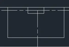
- Select the Line tool by entering 'LINE' command in the command tab.
- Keep Ortho on.
- Specify the start point.
- Draw footing of size 4' x 5'.
- Press Esc.
- Select the Offset tool by entering 'OFFSET command in the command tab.
- Specify offset distance as 3'.
- Select the bottom edge of the rectangle and click upwards.
- Press Esc.
- Select the Offset tool by entering 'OFFSET command in the command tab.
- Specify offset distance as 2'.
- Select the right edge of the rectangle and click inside.
- Press Esc.
- Select the Trim tool by entering TR command in the command tab.
- Press ENTER.
- Select Edge option; and click on No Extend.
- Select the unwanted lines to trim.
- Press 'Esc' to cancel the TRIM command
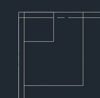
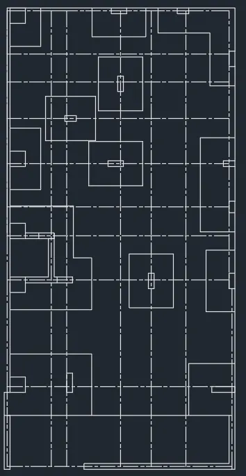
STEP 6
- Select the Hatch tool, by entering H command, select ANSI32 pattern, and set the hatch scale as per requirement, pick the point inside the wall of thickness 9".
- Press Esc.
- Select the Hatch tool, by entering H command, select ANSI37 pattern, and set the hatch scale as per requirement, pick the point inside the columns.
- Press Esc.
- Select the Hatch tool, by entering H command, select ARCONC pattern, and set the hatch scale as per requirement, pick the point inside the wall of thickness 4.5".
- Press Esc.
- Select the dimension and text layer.
- Enter 'DST command in the command tab to open the Dimension Style Manager dialog box.
- Click on the Modify tab.
- Under the Primary units tab select 'Architectural' in Unit format;' 0'-0 1/2"' in Precision.
- Under the Symbols and Arrows option change the Arrow size to 5".
- Under the Text option change the Text height to 6".
- Click OK. Then click on Set Current and Close the dialog box.
- Select the Dimension tool by entering 'DIM' in the command line.
- Select the first point and second point of the object to be measured, then drag the dimension line to the desired location. Repeat for all the objects to be measured.
- Enter 'MTEXT command in the command line.
- Specify the start point of text as required.
- Scale the text to the desired size.
- Copy the text box to wherever necessary.
- Enter ED in the command promt and edit the text boxes as required.
- Click Enter and press Esc.
RESULT