Creating a Wardrobe detailed drawing, Floor Plan, Kitchen Layout and Column Detail using AutoCad
CHALLENGE-6
PREPARED BY- MEGHA GUPTA
Creation a wardrobe detailed drawing, floor plan, kitchen layout and column layout using AutoCAD.
Aim: Aim of the challenge is to create the wardrobe detailed drawing, floor plan, kitchen layout and column layout using AutoCAD.
Introduction: In this project floor plan, wardrobe detailed drawing, kitchen layout and column layout have been created using various tools available in AutoCAD.
To create the various sketches line, rectangle, circle command has been used to draw the tables and annotation command to write the text. Hatch command is used for showing the brick wall and concrete. Different layers have been used for creating the drawings.
Procedure followed for creating the schedule and drawing template has been discussed below with each of the drawing.
- Draw the elevation details of a wardrobe as shown in the figure below. After sketching, you need to provide the dimensions and text with the use of layers. Use proper text styles and dimension methods to document it. Also, assume dimensions, wherever needed.
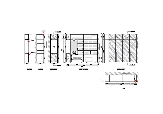 Fig. 1: Details of a wardrobe
-
Procedure followed for drawing of wardrobe details:
- Select the current drawing units as decimal.
- Select line command from the toolbar to create the boundary of the wardrobe for front elevation referring to Fig. 1.
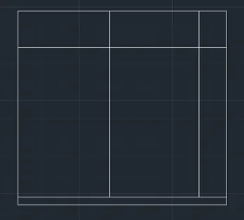
Fig. 2
- Using line command and offset command from the toolbar to create the sections of the wardrobe referring to Fig. 1.
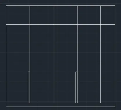
Fig. 3
- Using line command from the toolbar and selecting dotted line in the bylayer and draw the sketch referring to Fig. 1.
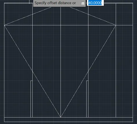
Fig. 4
- Using circle command from the toolbar draw the handle for the wardrobe.
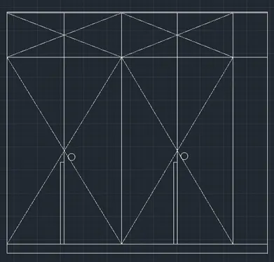
Fig. 5
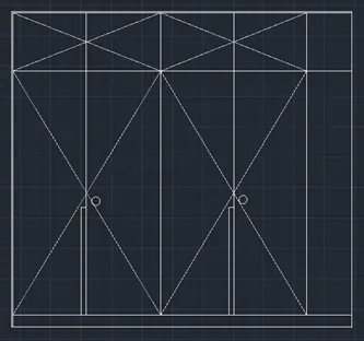
Fig. 6
- Select line command from the toolbar to create the boundary of the wardrobe for carcase elevation referring to Fig. 1.
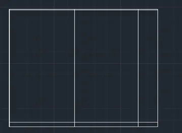
Fig. 7
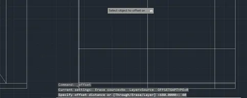
Fig. 8
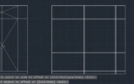
Fig. 9
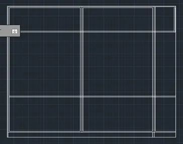
Fig. 10
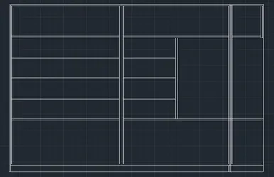
Fig. 11
- Trim command is used at different places to delete the unwanted portions and extend command has been used to extend the lines wherever required.
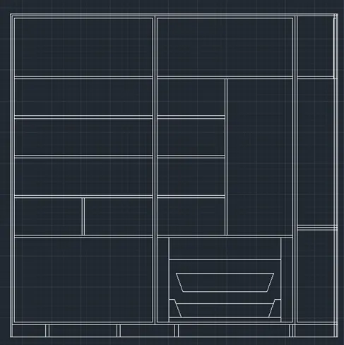
Fig. 11
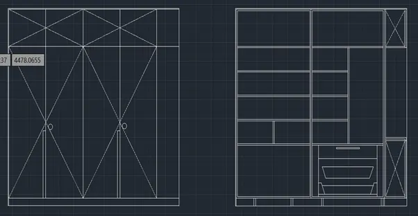
Fig. 12
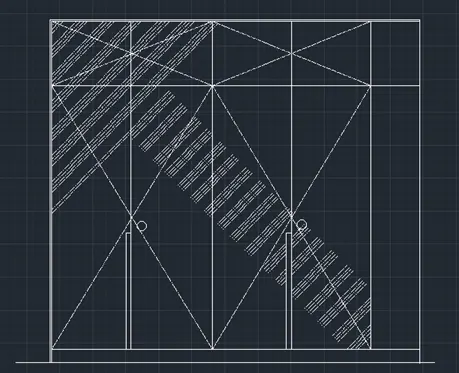
Fig. 13
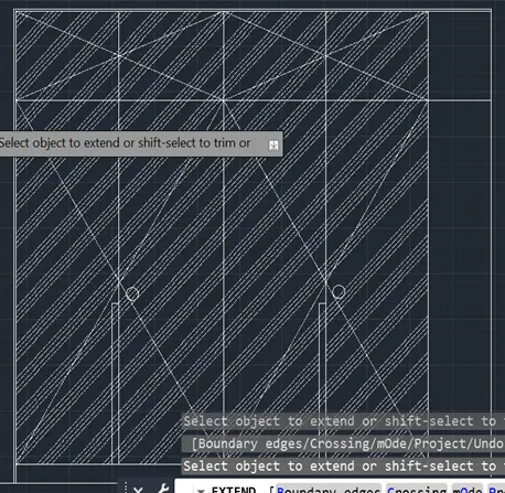
Fig. 14
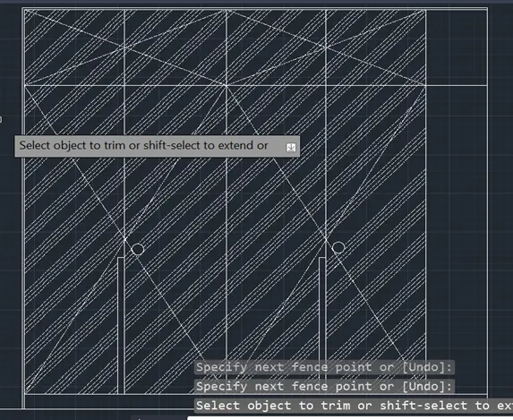
Fig. 15
- Line command is used to draw sections of the wardrobe.
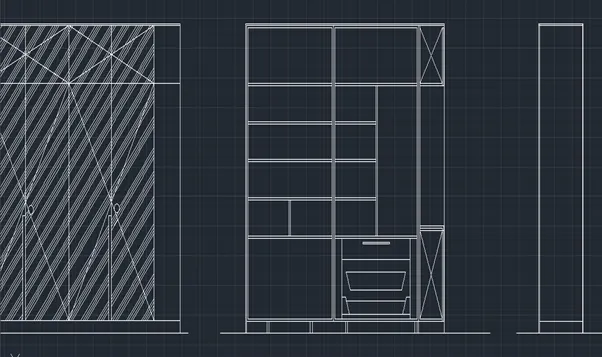
Fig. 16
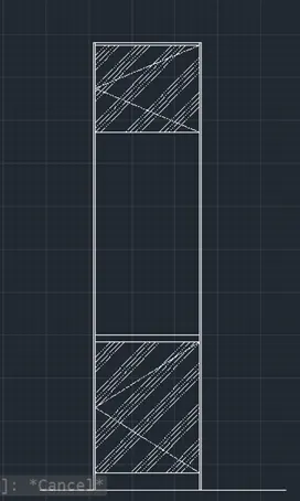
Fig. 17
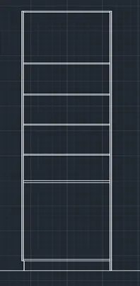
Fig. 18
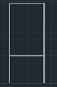
Fig. 19
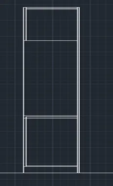
Fig. 20
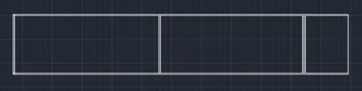
Fig. 21
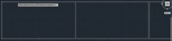
Fig. 22
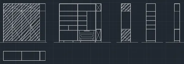
Fig. 23
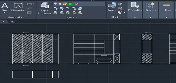
Fig. 24
- Sketch of the wardrobe was done in zero layer.
- For text another was added and different colour was selected.
- Turning on the text layer different text was written using annotation command referring to Fig. 1.
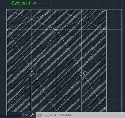
Fig. 25
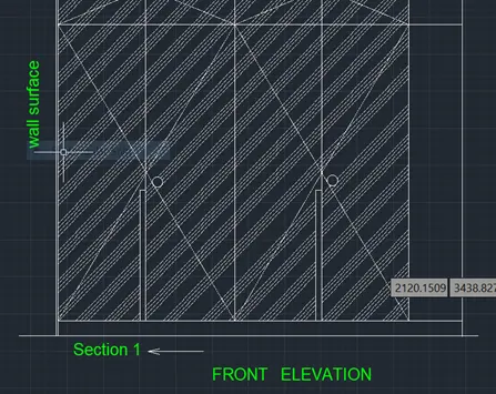
Fig. 26
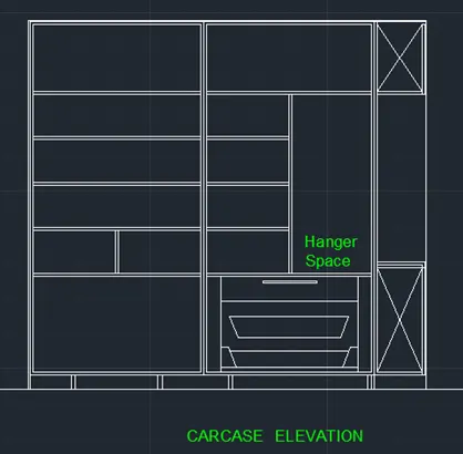
Fig. 27
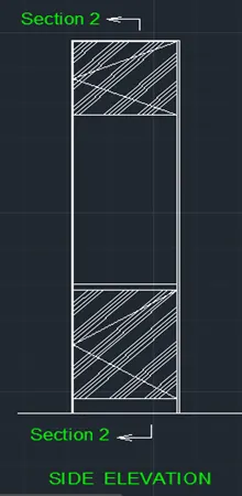
Fig. 28
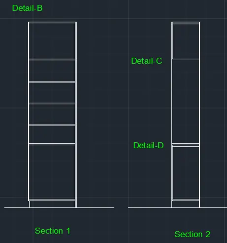
Fig. 29
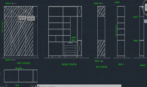
Fig. 30
- For dimension another was added and different colour was selected.
- Turning on the dimension layer different text was written using annotation command referring to Fig. 1.
Fig. 31
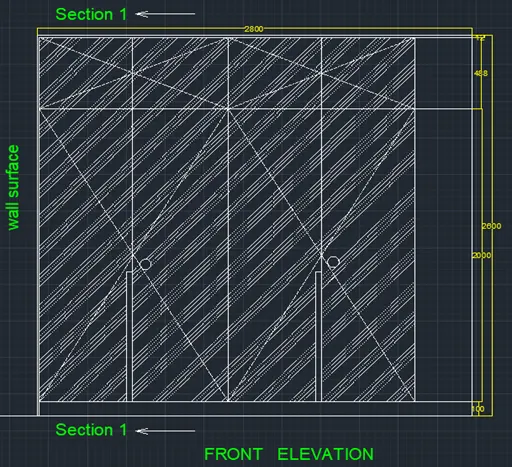
Fig. 32
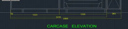
Fig. 33
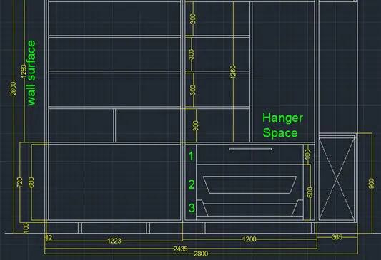
Fig. 34
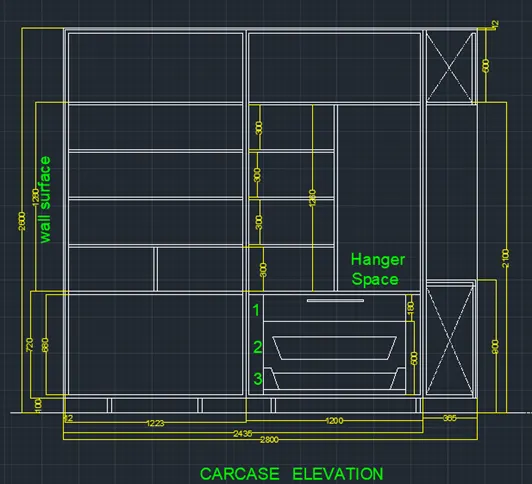
Fig. 35
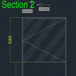
Fig. 36
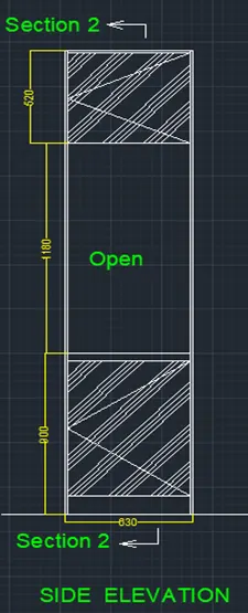
Fig. 37
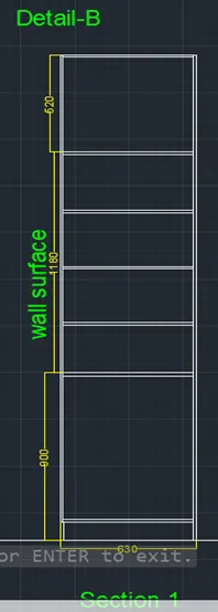
Fig. 38
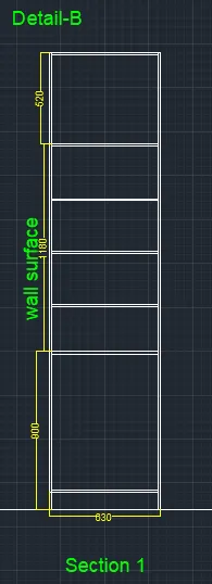
Fig. 39
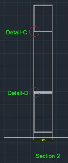
Fig. 40
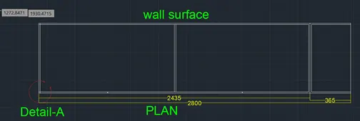
Fig. 41
- Draw the floor plan as shown in Figure. Use the proper drafting tools to sketch the plan. Do not hatch or draw the furniture. You need to draw the floor plan with the following:
- Wall (Exterior and Interior):
a. Wall thickness: Exterior Wall- 230mm, Interior Wall: 150mm (wherever required)
b. Doors and windows: Assume the size of doors and window.
Stairs: Tread- 300mm, Riser- 150mm
c. Insert text wherever required
d. Insert the dimensions using proper dimension techniques
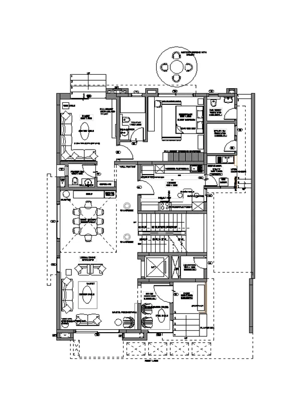
Fig. 42
Procedure followed for drawing the floor plan:
- Select the current drawing units as decimal.
- Create different layers for wall, doors, text and dimension.
- Select line command from the toolbar to create the walls of the plan referring to Fig. 42.
- Offset command is used so as to draw thickness of the wall.
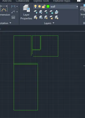
Fig. 43
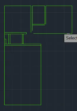
Fig. 44
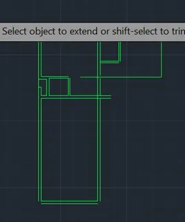
Fig. 45
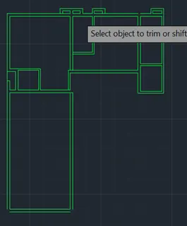
Fig. 46
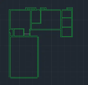
Fig. 47
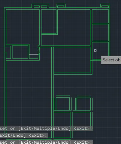
Fig. 48
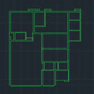
Fig. 49
- Use line and offset command to draw stairs.
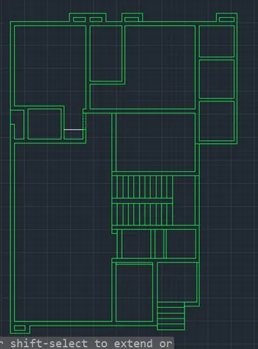
Fig. 50
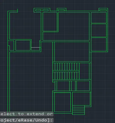
Fig. 51
- Use line and select the dotted line in bylayer in order to draw the extended portion of slab.
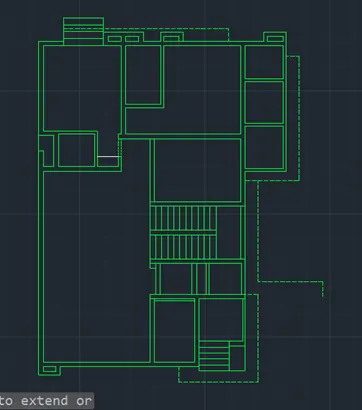
Fig. 52
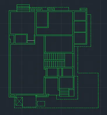
Fig. 53
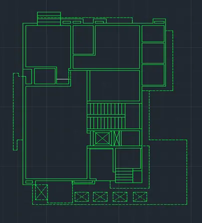
Fig. 54
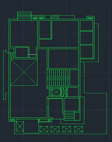
Fig. 55
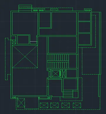
Fig. 56
- Use circle command, offset command to draw canopy and chair.
- Use Array command to create copies of the chair around the table.
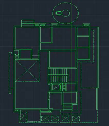
Fig. 57
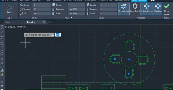
Fig. 58
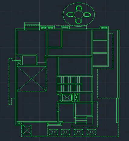
Fig. 59
- Select door layer and use line command to draw the doors and window.
- Circle command is used to draw the curve for showing the door movement.
- Trim command is used to remove unwanted portion.
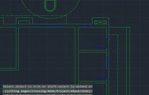
Fig. 60
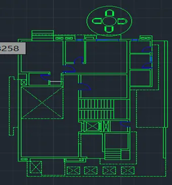
Fig. 61
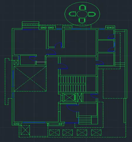
Fig. 62
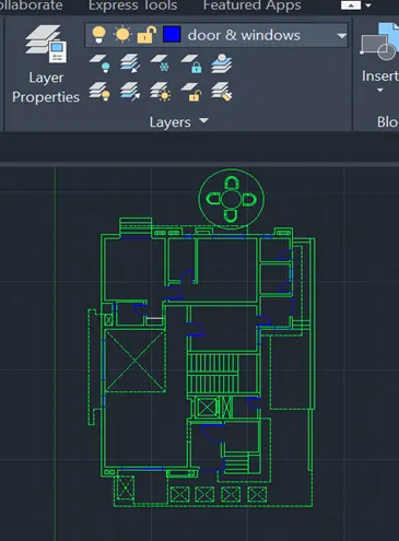
Fig. 63
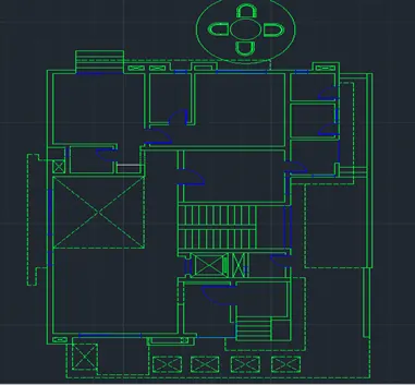
Fig. 64
Select text layer and use annotation command to specify room name and sizes.
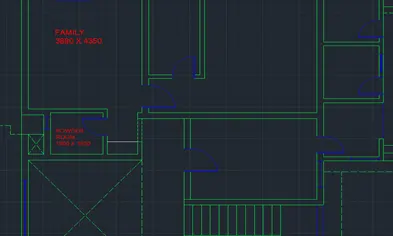
Fig. 65
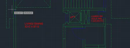
Fig. 66
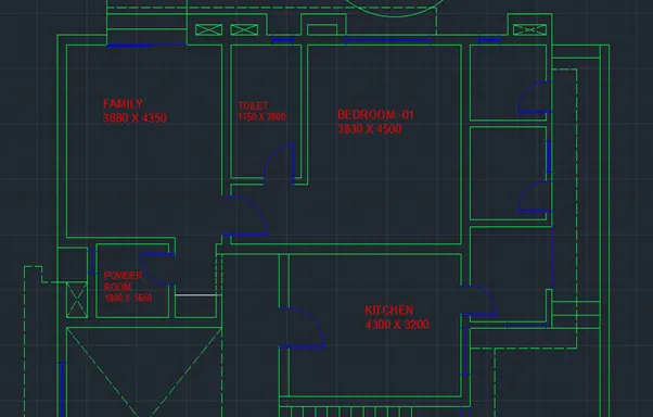
Fig. 67
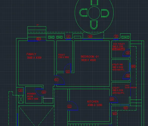
Fig. 68
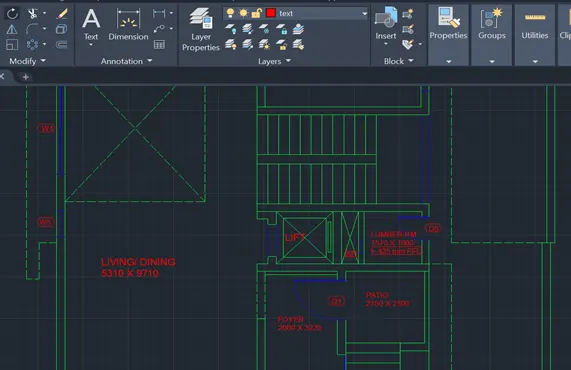
Fig. 69
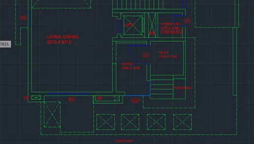
Fig. 70
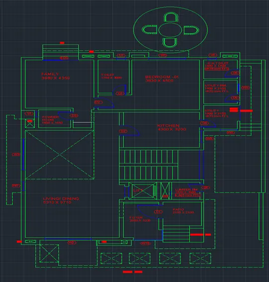
Fig. 71
3. Create the kitchen layout as shown in the figure below. Also, use proper dimension techniques to dimension the kitchen layout. Also, insert text wherever required. All dimensions are in mm.
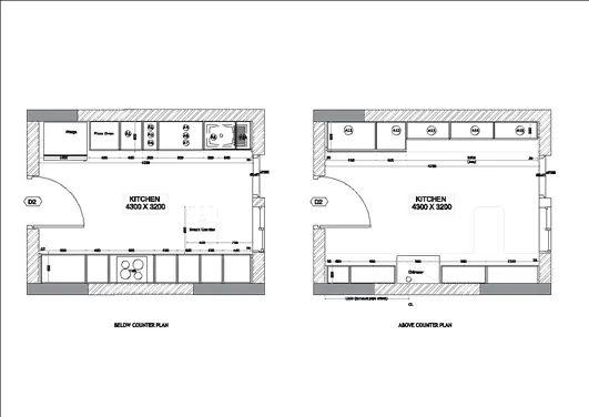
Fig. 72
Procedure followed for drawing the kitchen layout:
- Select the current drawing units as decimal.
- Create different layers for wall, doors, text and dimension.
- Select line command from the toolbar to create the walls of the plan referring to Fig. 72.
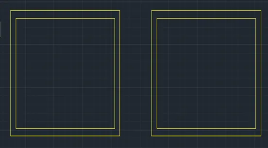
Fig. 73
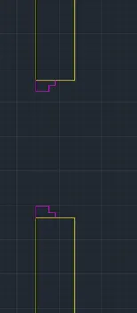
Fig. 74
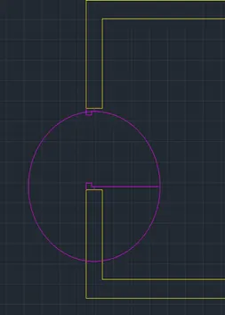
Fig. 75
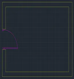
Fig. 76
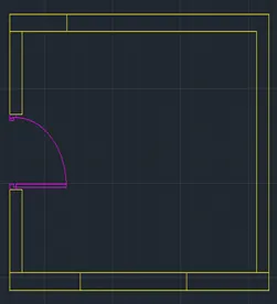
Fig. 77
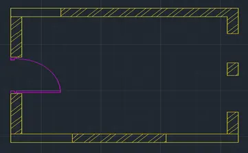
Fig. 78
- Select the hatching for the walls from hatch command.
- Use line command to draw the windows.
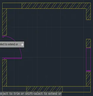
Fig. 79
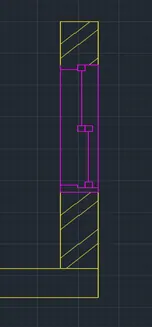
Fig. 80
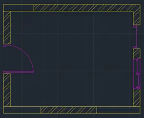
Fig. 81
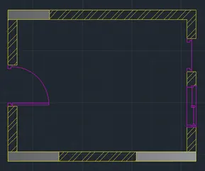
Fig. 82
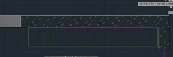
Fig. 83
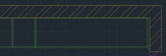
Fig. 84
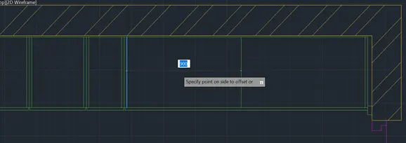
Fig. 85
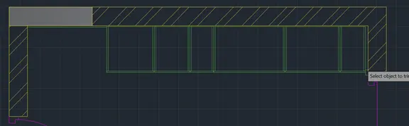
Fig. 86
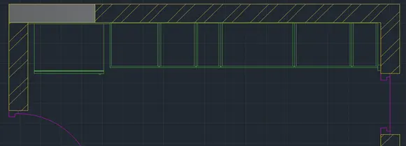
Fig. 87
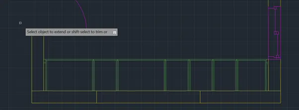
Fig. 88
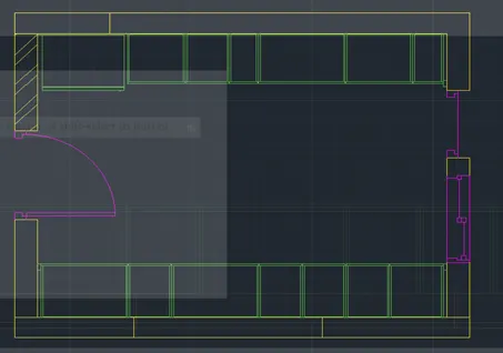
Fig. 89
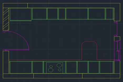
Fig. 90
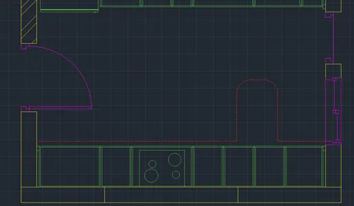
Fig. 91
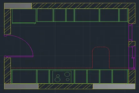
Fig. 92
- Turn on the text layer and write the details annotation command.
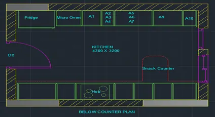
Fig. 93
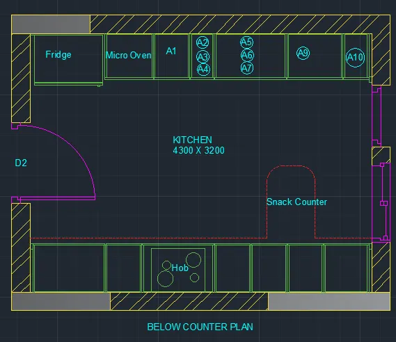
Fig. 94
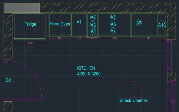
Fig. 95
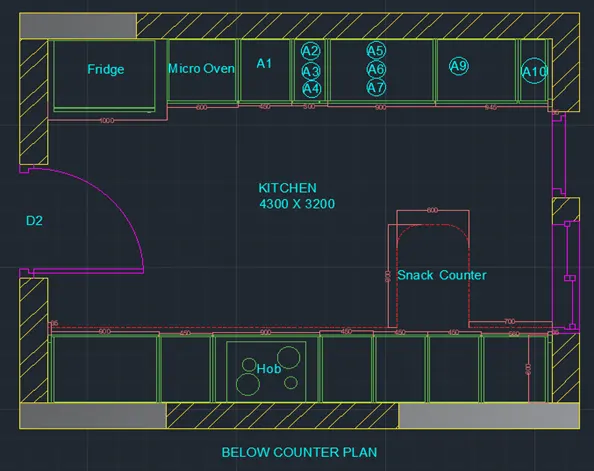
Fig. 96
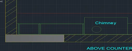
Fig. 97
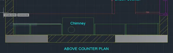
Fig. 98
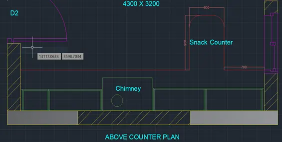
Fig. 99
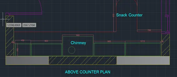
Fig. 100
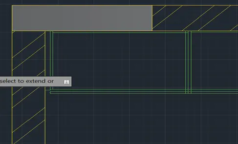
Fig. 101
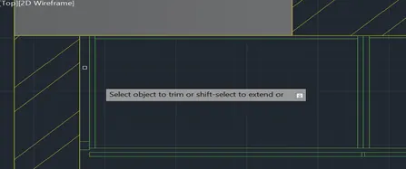
Fig. 102
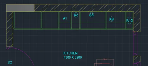
Fig. 103
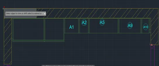
Fig. 104
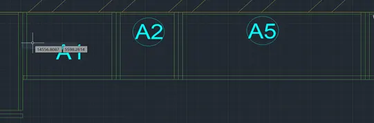
Fig. 105
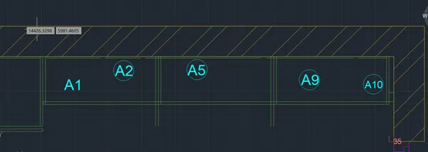
Fig. 106
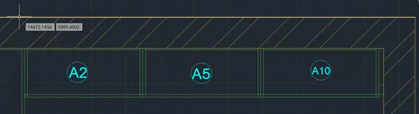
Fig. 107
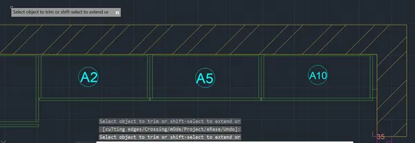
Fig. 108
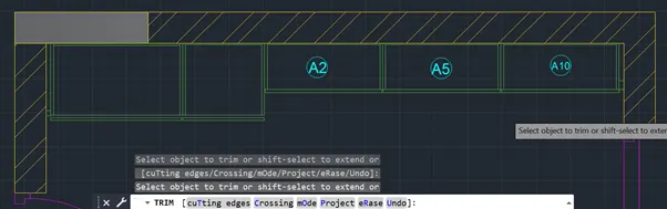
Fig. 109
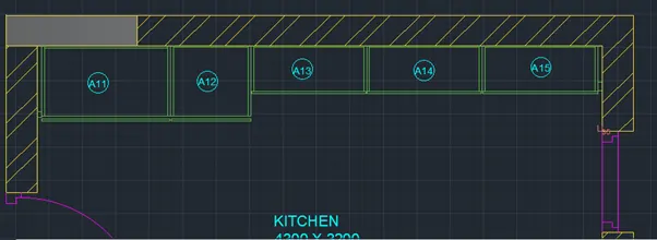
Fig. 110
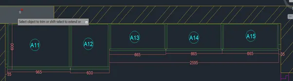
Fig. 111
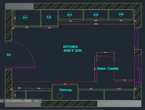
Fig. 112
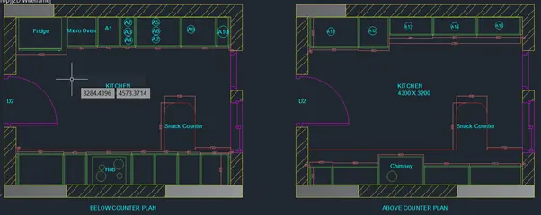
Fig. 113
- Sketch the column details as shown in Figure. Insert dimensions and text in the figure. Refer to the bar sizes from the schedule.
8mm ---- 0.31 Inches
25mm--- 1 inches
16mm—0.62 inches
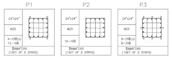
Fig. 114
Procedure followed for drawing the column schedule:
- Select the current drawing units as architectural.
- Select line command from the toolbar to create the table referring to Fig. 114.
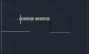
Fig. 115
- Select line command from the toolbar to create the column cross section.
- Offset command is used for drawing the reinforcement at 1.57 inch cover.
- Corners were provided with curve using fillet command.
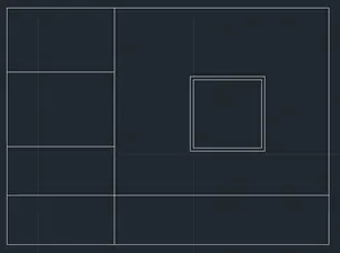
Fig. 116
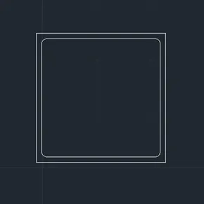
Fig. 117
- Select circle command from the toolbar to create the cross section of reinforcement. Diameter of the bar is followed as per Fig. 114. 1” diameter of circle is used for 25mm bar.
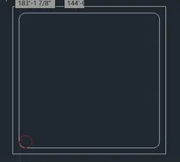
Fig. 118
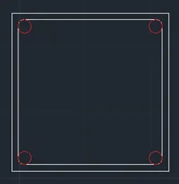
Fig. 119
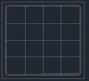
Fig. 120
- Offset, trim and extend commands are used for drawing the stirrups.
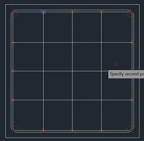
Fig. 121
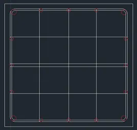
Fig. 122
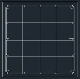
Fig. 123
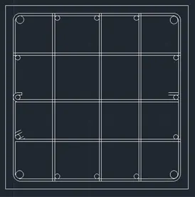
Fig. 124
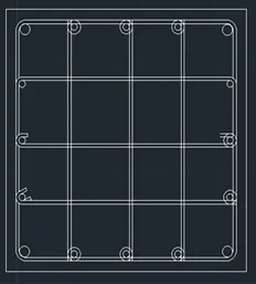
Fig. 125
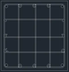
Fig. 126
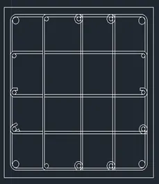
Fig. 127
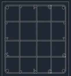
Fig. 128
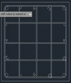
Fig. 129
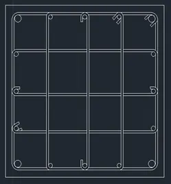
Fig. 130
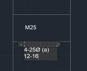
Fig. 131
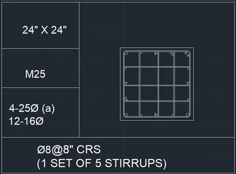
Fig. 132
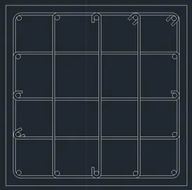
Fig. 133
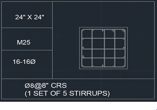
Fig. 134
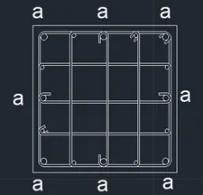
Fig. 135
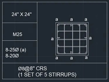
Fig. 136
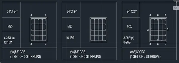
Fig. 137
5. Draw the Raft Layout as shown in the Figure. Assume the column size as per your knowledge. You can take the sizes as: 24”x24”, 9” x 24”, 9” x 18”, and 9’ x 24”. You can import the raft_foundation.pdf to ensure the missing dimensions.
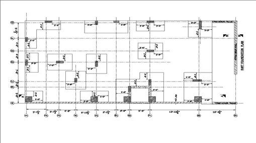
Fig. 138
Procedure followed for creating raft footing layout:
- Select the current drawing units as architecture.
- Select line command from the toolbar to draw the boundary of raft footing.
Fig. 139
- Select the center line in the ByLayer and draw the centerline for columns referring to Fig. 138.
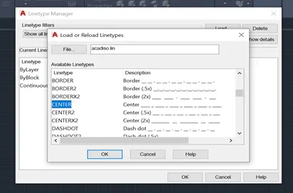
Fig. 140
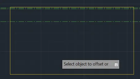
Fig. 141
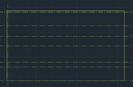
Fig. 142
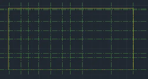
Fig. 143
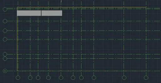
Fig. 144
- Draw circles at the end of center line to mark the number for center line referring to Fig. 138.
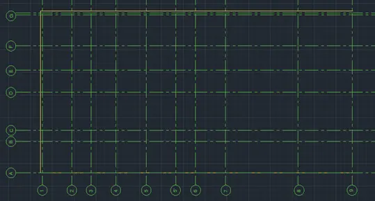
Fig. 145
- Use line command to draw columns etc on raft layout.
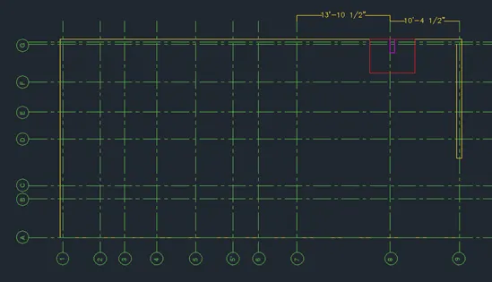
Fig. 146
- Use hatch toolbar to show hatching for the columns.
- Use dimensions to specify the dimensions in the layout.
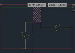
Fig. 147
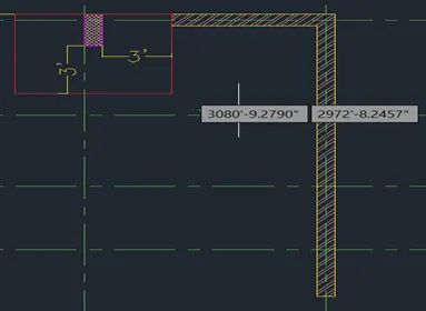
Fig. 148
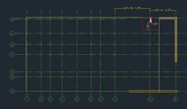
Fig. 149
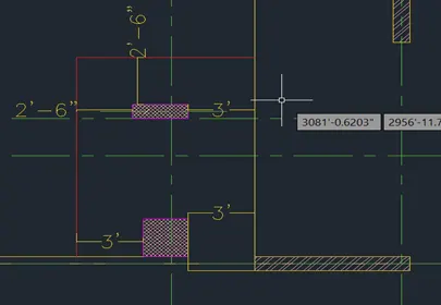
Fig. 150
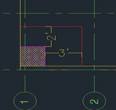
Fig. 151
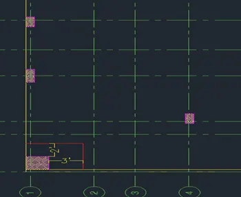
Fig. 152
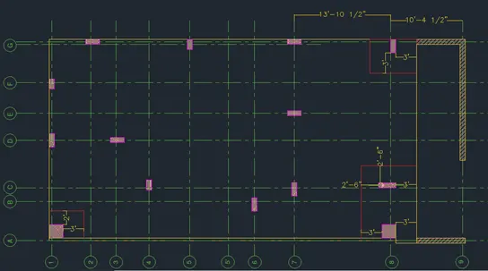
Fig. 153
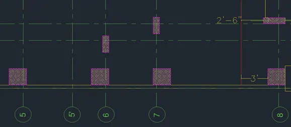
Fig. 154
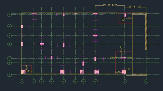
Fig. 155
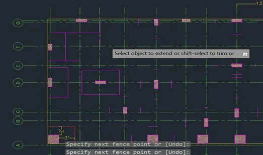
Fig. 156
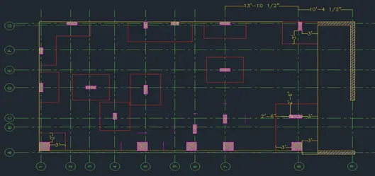
Fig. 157
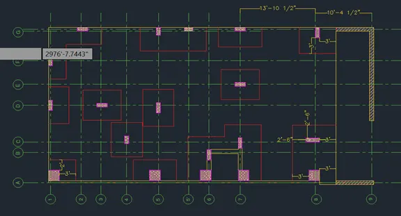
Fig. 158
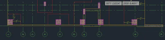
Fig. 159
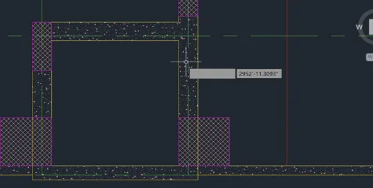
Fig. 160

Fig. 161
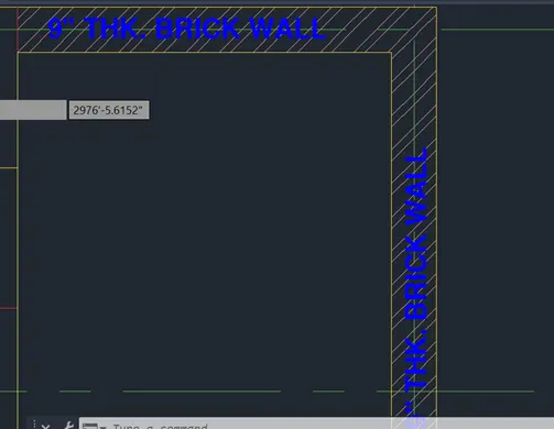
Fig. 162
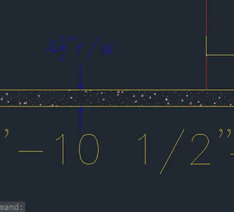
Fig. 163
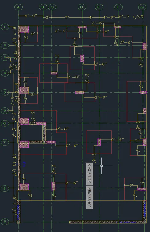
Fig. 164