Creating a Wardrobe detailed drawing, Floor Plan, Kitchen Layout and Column Detail using AutoCad
AIM - Creating a Wardrobe detailed drawing, Floor Plan, Kitchen Layout and Column Detail using AutoCad.
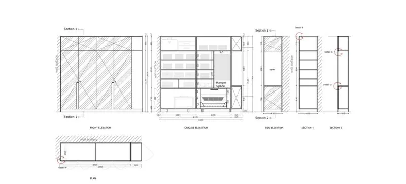
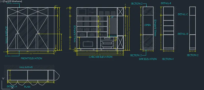
Q1. Draw the elevation and details of a wardrobe as shown in the Figure below. After sketching, you need to provide the dimensions and text with the use of layers. Use proper text styles and dimension methods to document it. Also, assume dimensions, wherever needed.
Note: All dimensions are in mm.
Procedure -
Type UN and press enter
Under Drawing Units, select decimal
Now the lower limit is set to 0, 0 and the upper limit to 10000, 10000
Type Z enter to zoom and A enter to all
First, the plan is drawn using line command. Type L and press enter
Specify the first point:(0,0)
Specify the next point: @2800,0
Specify the next point: @0,630
Specify the next point: @-2800,0
Specify the next point: C
Type O or offset on the command line and press Enter.
Specify the value of offset distance:20
Select the line to offset and click inside it
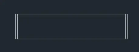
Type O or offset on the command line and press Enter.
Specify the value of offset distance:1223
Select the line to offset and click outside it
A similar way offset is done for 20 and 1220 as shown in figure
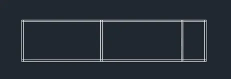
Using the Trim command the unwanted lines are trimmed off and the resulting image is obtained
A rectangle in the shape of L is created on the plan and a hatch is applied to it
Type H and press enter, the required pattern is selected, and the transparency is made to 85% and the area to be hatched is selected. After hatching delete the rectangles
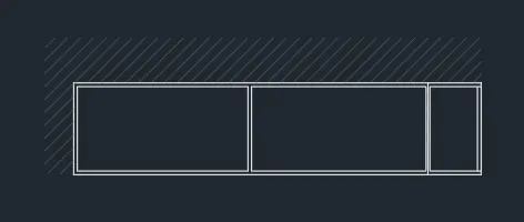
Now by keeping on the polar tracking at 45 degree lines are dawn and using the start end direction option in arcs the arcs are created and the obtained image is follows
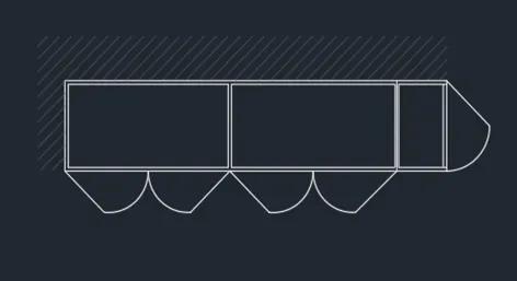
Using the Dimlin command the first dimension is marked and by using dimcontinue command the rest of the dimensions is made
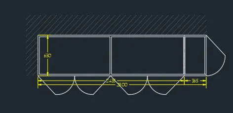
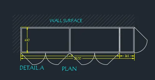
Using single line text the texts required are made and the final image of plan is as follows
Next, the front elevation was plotted in order to do that the lines from the plans were extended to get the correct position of the lines and the corresponding image was plotted based on the dimensions given in the question.
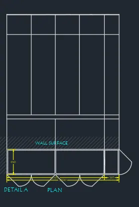
Now using the line command cross bracings was given and as per the question.
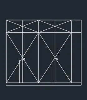
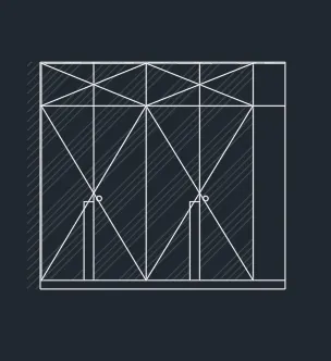
Now hatch is applied to it
Type H and press enter, the required pattern is selected, and then the transparency is made to 85% and the area to be hatched is selected.
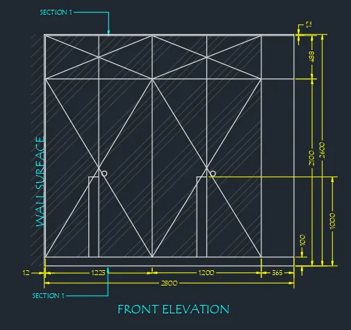
Using the Dimlin command the first dimension is marked and by using dimcontinue command the rest of the dimensions is made
Using single line text the texts required are made and the final image of front elevation is as follows
The carcase elevation is drawn next, it has the same outline as that of front elevation and its base drawing was copied to begin with.
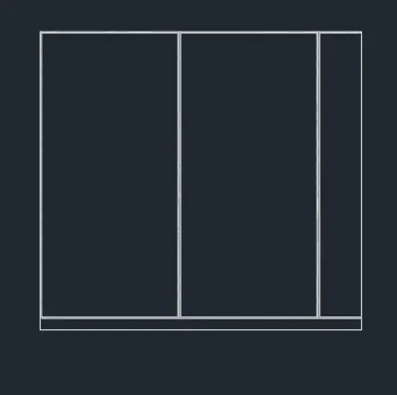
Using the line and offset command the legs of wardrobe was created and the resultant image is as follows.
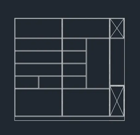
Using the rectangle, arc, lines, offset commands the internal detailing was done with transparency value of 70. Hatching was also done at the side as required.
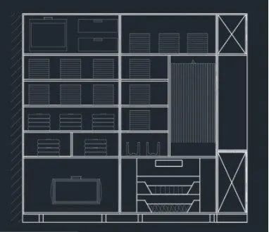
Using the Dimlin command the first dimension is marked and by using dimcontinue command the rest of the dimensions is made
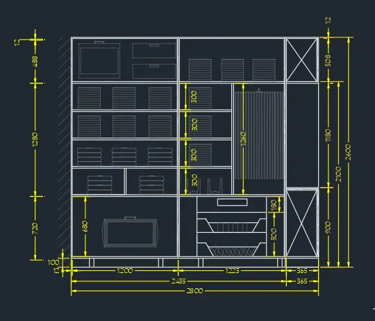
Using single line text the texts required are made and the final image of carcase elevation is as follows
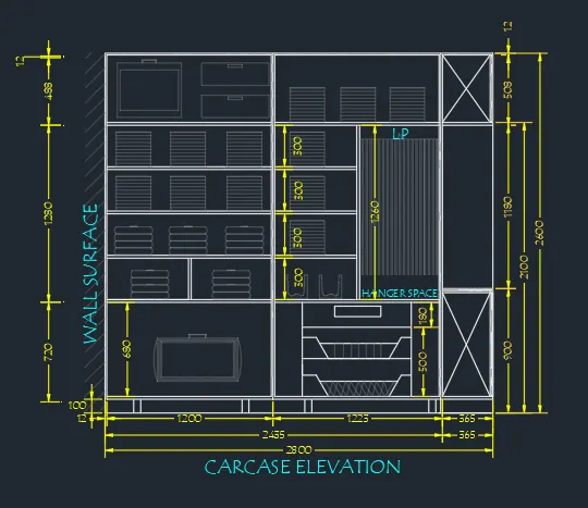
Next, the side elevation was drawn.
For that, a rectangle of size 630x2600 was created, and an offset of 20 was made on the rectangle. As per plan using the line command, the lines was drawn and the resultant image is as follows
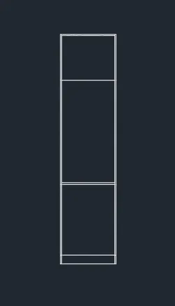
Hatching was provided next as required and as provided in the question and transparency was set to 85
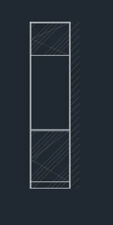
Using the Dimlin command the first dimension is marked and by using dimcontinue command the rest of the dimensions is made.
Using single line text the texts required are made and the final image of side elevation is as follows
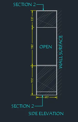
Next section 1 was drawn, it has the same outline as that of side elevation and that was used for starting and using the line command the necessary lines was drawn and offsetted to get the following figure
Hatching was provided next as required and as provided in the question and transparency was set to 85
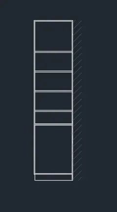
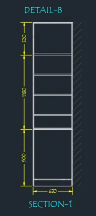
Using the Dimlin command the first dimension is marked and by using dimcontinue command the rest of the dimensions is made
Using single line text the texts required are made and the final image of section 1 is as follows
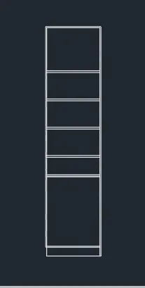
Next the section 2 was drawn by creating a rectangle of size 365x2600 and is offsetted at required places by 20. Using the line command the required lines as plotted as in the question.
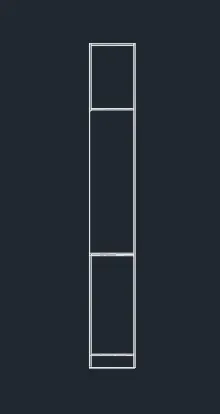
Using the Dimlin command the first dimension is marked.
Using single line text the texts required are made and the final image of section 2 is as follows
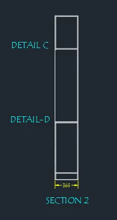
Result - The entire drawing is now complete and the resultant image of the finished drawing is as shown in figure.
Q2.
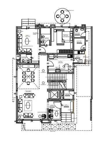
Draw the floor plan as shown in the Figure. Use the proper drafting tools to sketch the plan. Do not hatch or draw the furniture. You need to draw the floor plan with the following:
Note: You can also import the Floor_Plan.pdf into your current drawing and start working on the project. You need to scale the imported pdf file using reference option. All dimensions are in mm.
- Walls (Exterior and Interior) Wall Thickness: Exterior Wall- 230mm, Interior Wall: 150 mm (Wherever Required)
- Doors and Windows: Assume the size of the doors and window.
Stairs: Tread-300mm, Riser-150mm
- Insert Text wherever required
- Insert the dimensions using proper dimension techniques
Procedure -
Type UN and press enter
Under Drawing Units, select decimal
Now the lower limit is set to 0,0 and upper limit to 7500, 7500
Type Z enter to zoom and A enter to all
1. External walls
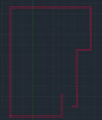
Using the construction line command XL horizontal and vertical lines was created. As the thickness of external walls is 230, an offset of 230 was created both vertically and horizontally. The edges and corners are trimmed off or filleted.
The vertical and horizontal construction lines are again offsetted, trimmed or filleted to get the external walls as per the plan and the following image was obtained.
Now all the external walls are completed.
2. Interior walls
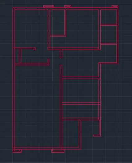
According to the plan the internal walls are drafted and the thickness of internal walls is taken as 150. The edges and corners after trimming or filleting the following image is obtained
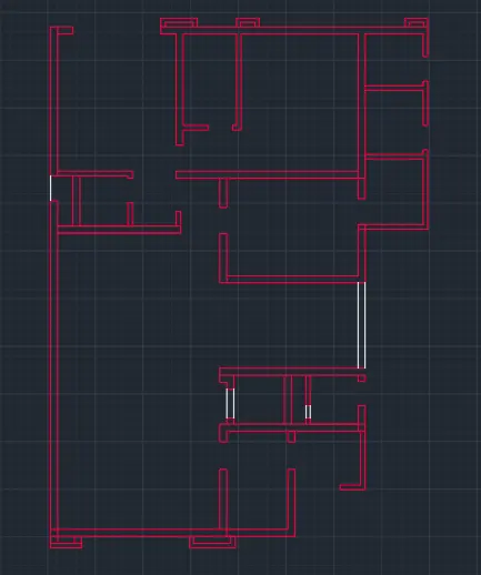
3. openings
Now using the trim command all the openings in interior and exterior walls was made for doors or for steps and the resultant image obtained is as follows.
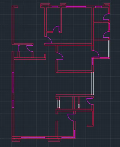
4. Doors and windows
Now using the line, circle, trim and offset tool doors of different sizes was drawn and by using the line tool and object snapping the windows was drawn and the following image is obtained
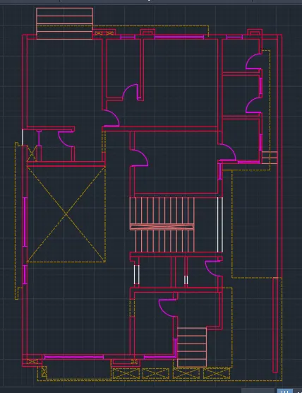
5. staircase steps and dotted lines
Now using the line and offset tool staircase and steps was drafted first. The dotted lines was also drawn as shown in figure
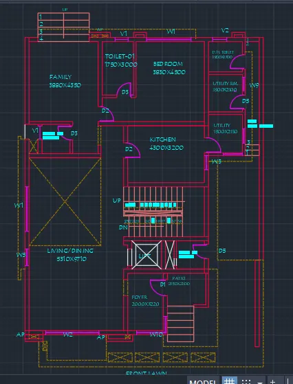
6. Texts
Now using the MTEXT command the texts was made and the following image is obtained.
7. Dimensions
Now using the Dimlin the dimensions was plotted and the following image is obtained
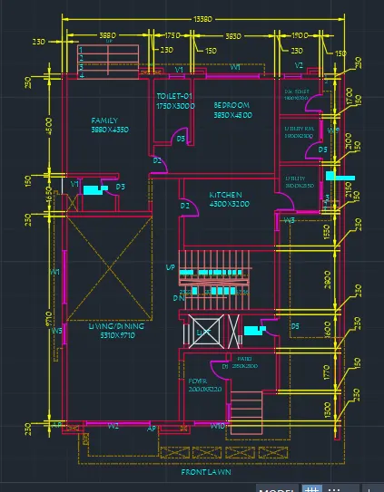
Result - Residential plan was drafted using AutoCAD
Q3. Create the Kitchen Layout as shown in the Figure below. Also, use proper dimension techniques to dimension the kitchen layout. Also, insert text wherever required. All dimensions are in mm.
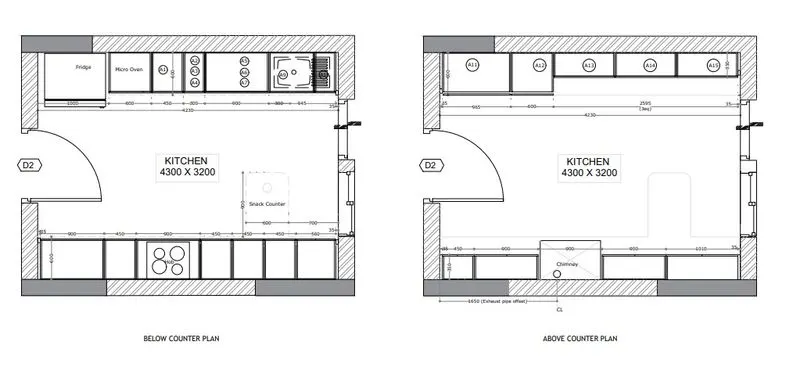
Procedure -
Type UN and press enter
Under Drawing Units, select decimal
Now the lower limit is set to 0,0 and upper limit to 15000, 15000
Type Z enter to zoom and A enter to all
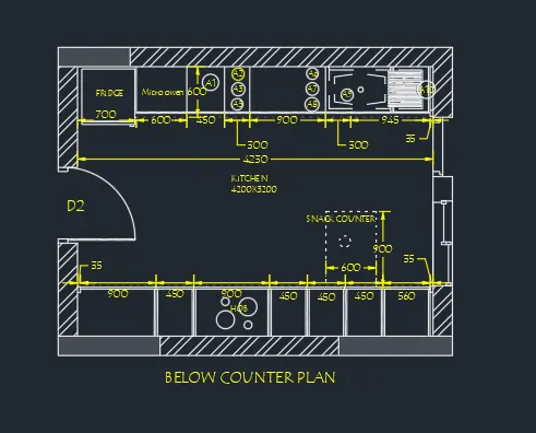
First of all the below counter plan was drawn. For that a rectangle of size 4734x3688 was created and an offset of 250 was taken to the inside of rectangle. Then a line was drawn from both sides at a distance of 600 mm.

A rectangle of width 35 is drawn at 3 corners in order to separate between the kitchen walls and the counter. Now using the line command all the cabinets was drawn as per the plan given.
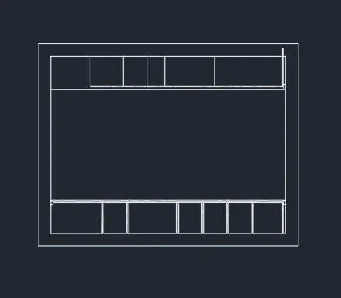
The circle command ws used to plot the hob line,arc and circle command was used to zinc at top corner and the snack counter was drawn using the dotted lines.
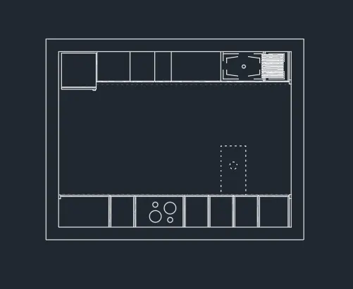
Door opening and doors was placed next and the components inside the walls was drawn as shown. This was done using line, offset and circle command
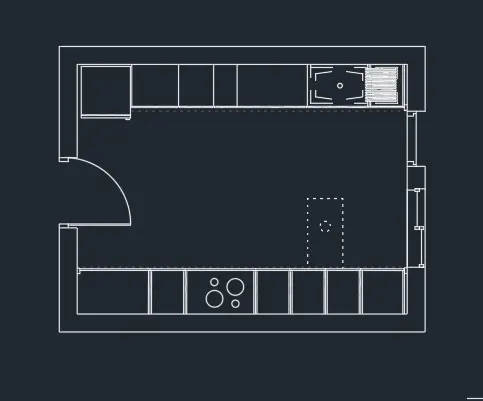
Now hatching was done with required solid and pattern styles and was set to a transparency to 75.
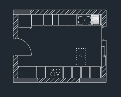
Now all the dimensions was plotted and all the text was plotted as required and the final image of below counter plan is as follows
The above counter plan was next plotted. The outline of this plan is way too similar to below counter plan only the difference is the size of counters. After drawing the counters, dimensioning and text placing was done and the final image of above kitchen plan is as follows
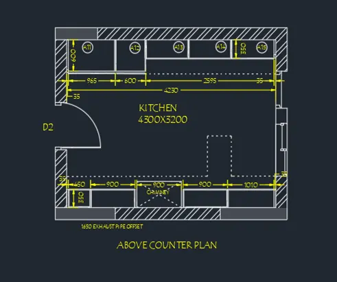
The above and below counter plan was plotted and the resultant image is as follows.
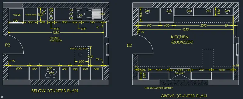
Result - Kitchen Layout is completed as shown in the Figure.
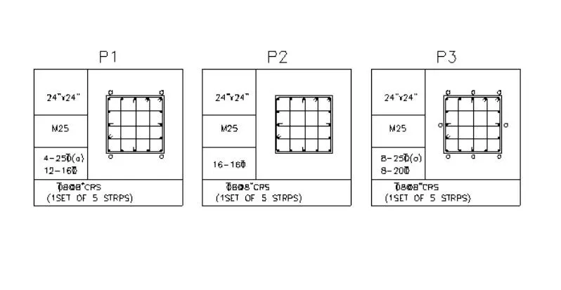
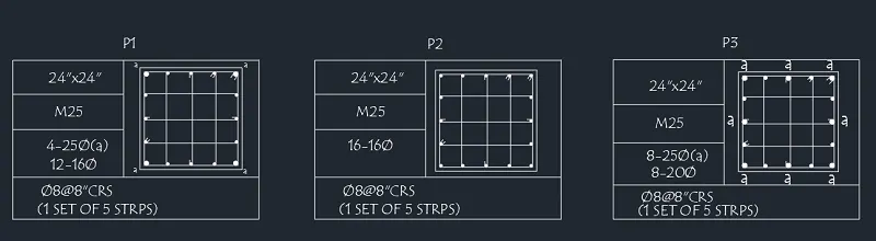
Q4. Sketch the column details as shown in Figure. Insert dimensions and text in the figure. Refer to the bar sizes from the schedule.
8mm ---- 0.31 Inches
25mm--- 1 inches
16mm—0.62 inches
Procedure -
Type UN and press enter Under Drawing Units, select the desired unit: Engineering.
And then the upper and lower limits was set
To draw the columns
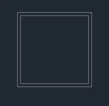
Type Rec or Rectangle in the command line and press Enter.
Specify the first corner of the rectangle.
Enter D for Dimensions.
Enter the length: 24”
Enter the width: 24”
Specify the other corner.
Type O or offset on the command line and press Enter.
Specify the value of offset distance:1.5”
Select the rectangle to offset and click inside it.
Turn on ortho mode.
Draw a line connecting the centre of rectangles in both horizontal and vertically
Type DIV and press enter
Select the centre line drawn
Specify the number of segements as 4 and press enter.
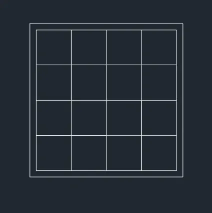
A circle of 1” and .62" diameter is drawn and is now placed at the respective places as per the figure and was then hatched
Using the same steps the other two column details was plotted.
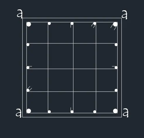
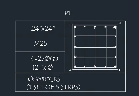
Table creation
Now using the line command a table was created based on the question
Type DTEXT and press enter
Specify the location to type text
Select rotation angle to o degree and start typing
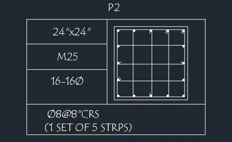
Now the above table is copied and placed and the above step is repeated
Now the above column is copied and placed and the above step is repeated
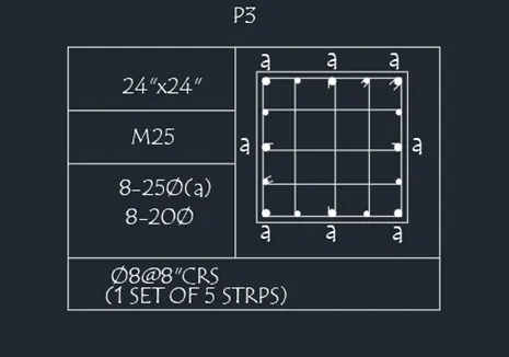
Result - Column scheduling is now completed and the final resultant figure is as given
Q5. Draw the Raft Layout as shown in the Figure. Assume the column size as per your knowledge. You can take the sizes as: 24”x24”, 9” x 24”, 9” x 18”, and 9’ x 24”. You can import the raft foundation.pdf to ensure the missing dimensions.
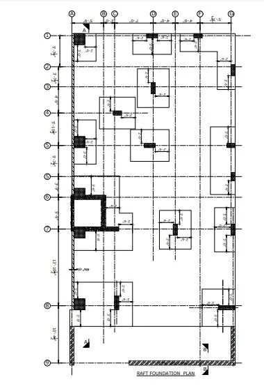
Procedure -
Type UN and press enter
Under Drawing Units, select Architectural
Now the lower limit is set to 0,0 and upper limit to 100', 100'
Type Z enter to zoom and A enter to all
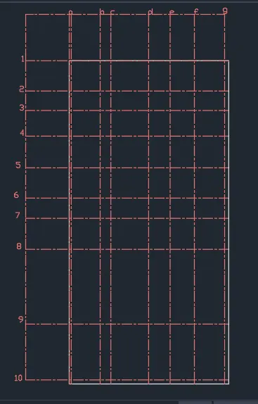
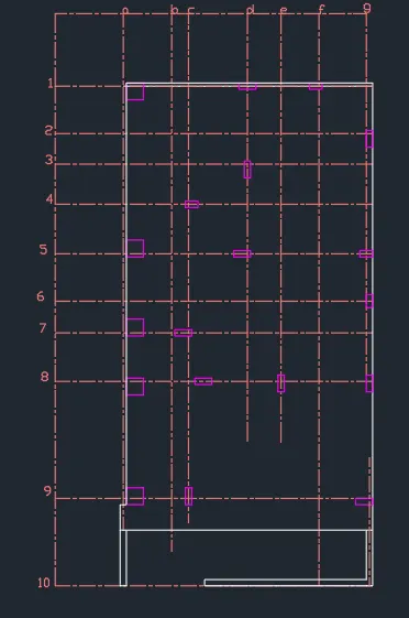
A rectangle b 297'5"x60' b long dash short dash dotted line was selected and the folllowing grid lines was drawn as per the dimension given in plan
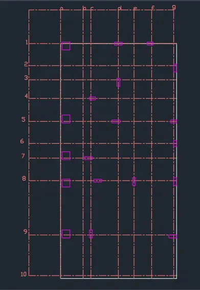
Now using the rectangle command the different sized columns was plotted as per the plan.
The various column sizes is as follows: 24"x24", 9"x24", 9"x18, and 9"x30
Next the 9" thick brickwall at the bottom of the plan was drawn using the line and offset command.
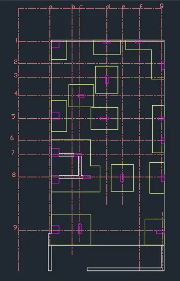
Now, by using the line command the footings of all the columns was drawn as shown.
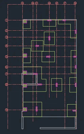
The hatching was done to the columns as required.
Dimensioning was completed next properly
All the text required was created using the sinle line text and a few of them was rotated to 90 degree as required
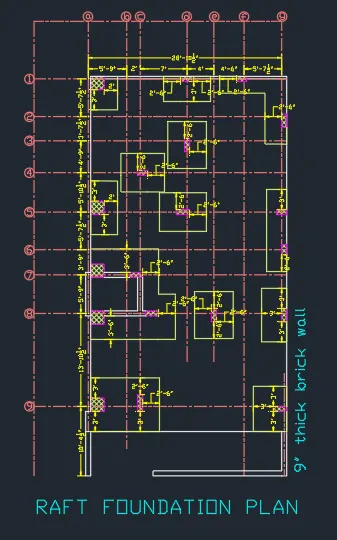
Result - The raft foundation plan was completed