Creating a Wardrobe detailed drawing, Floor Plan, Kitchen Layout and Column Detail using AutoCad
Aim:-
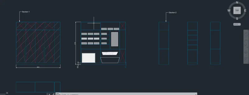
Draw the elevation and details of a wardrobe Using Auto Cad
Note:- All the Dimensiones are in mm
Procedcure:-
- Give the Command of Units press Enter
- Select the Units as Decimal and Insertion Scale in mm Click Ok
- Give the Command of XL enter Select V and Enter
- Place the Vertical Line Corner of the Work space Press Enter
- Give the Command of Offset and Press enter
- Specify the Offset Distance as 2800 and Select the Vertical line to Offset
- Press Esc.,
- Types Offset and Press Enter
- Specify the Offset Distance as 12 and Press enter
- Give the offset as 12 on Both Sides of Vertical Lines
- Press Esc
- Give the Command of XL and Select H and press enter
- Specify the Offset Distance as 100 and Select the Horizontal Line to Offset
- Press Esc.,
- Give the Offset Command and Press enter
- Specify the Offset distance as 2100 Press enter From Previous offseted Line
- Press Esc
- Give the Command of Offset Press enter
- Specify the Distance as 488 and Select previously Offseted Line Press Enter
- Give the Command of Offset Press enter
- Specify the Distance as 12 and Select previously Offseted Line Press Enter
- Press Esc.,
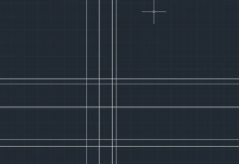
- Give the Command of XL and Select H and press enter
- Specify the Point as Below the Starting Line
- Give the Offset Command and Give the Offset Distance as 12 and Select the Horizontal Line to Offset
- Press Esc.,
- Give the Offset Command and Give the Offset Distance as 630 and Select the Horizontal Line to Offset
- Press Esc.,
- Give the Offset Command and Give the Offset Distance as 12 and Select the Horizontal Line to Offset
- Press Esc.,
- Select the Vertical Line and Give the Command of Offset and Give the Offset Distance as 1217.5 and press Enter
- Press Esc.,
- Give the Offset Command and Give the Offset Distance as 12 and Select the Horizontal Line to Offset
- Press Esc.,
- Select the Vertical Line and Give the Command of Offset and Give the Offset Distance as 377 and press Enter
- Press Esc.,
- Give the Offset Command and Give the Offset Distance as 12 and Select the Horizontal Line to Offset
- Press Esc.,
- Trim the Unnecessary Lines By Giving the Trim Command
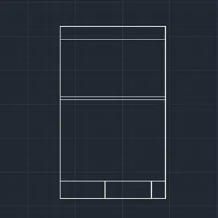
- Select the Right side of the Vertical Line Give the offset Command and Give the Offset distance as 377 and Press Enter
- Press Esc.,
- Select the Vertical Line and Give the Command of Offset and Give the Offset Distance as 602.8 and press Enter
- Press Esc.,
- Select the Vertical Line and Give the Command of Offset and Give the Offset Distance as 602.8 and press Enter
- Press Esc.,
- Select the Vertical Line and Give the Command of Offset and Give the Offset Distance as 602.8 and press Enter
- Press Esc.,
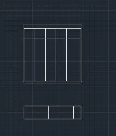
- In the Ribbon tab select Layer Properties Click on New Layer In the Layer Properties
- Create the Layer as Transparent and Changes the transparency value as Suitable Limit
- Set as Current Layer Change the Colour to Red and Close the Tab
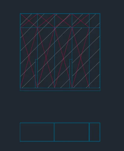
- Select the Line tool From Ribbon Tab and Specify the Starting point as Left side of the Bottom Corner Point
- Draw Diagonal Line Connection the Right Top Corner
- Press Esc.,
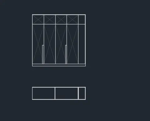
- Similarly Draw lines Using Line tool From the Ribbon Tab According Given Figure
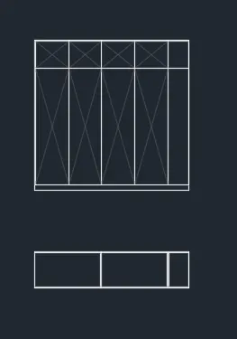
- Draw a Door Panel By Using Rectangle Command
- Specify the Starting Point as Corner of Select the Dimensions and Give the length as 80and Breadth as 995 Press Enter
- Draw a another Door Panel By Using Rectangle Command
- Specify the Starting Point as Corner of Select the Dimensions and Give the length as 80and Breadth as 995 Press Enter
- Press Esc.,
- In the Ribbon tab select Layer Properties Click on New Layer In the Layer Properties
- Create the Layer as Border Lines
- Set as Current Layer Change the Colour to Blue and Close the Tab
- Select the Border Lines Changes to Current Layer
- Give the Command of XL and Select V and press enter
- Specify the Point as Below the Starting Line
- Give the Offset Command and Give the Offset Distance as 12 and Select the Vertical Line to Offset
- Project the Horizontal Lines
- Select the Horizontal Lines and give the Command of Offset and press enter Give the Offset Length as 300 Press enter press Esc.,
- Select the Horizontal Lines and give the Command of Offset and press enter Give the Offset Length as 12 Press enter press Esc.,
- Select the Horizontal Lines and give the Command of Offset and press enter Give the Offset Length as 300 Press enter press Esc.,
- Select the Horizontal Lines and give the Command of Offset and press enter Give the Offset Length as 12 Press enter press Esc.,
- Select the Horizontal Lines and give the Command of Offset and press enter Give the Offset Length as 300 Press enter press Esc.,
- Select the Horizontal Lines and give the Command of Offset and press enter Give the Offset Length as 12 Press enter press Esc.,
- Select the Horizontal Lines and give the Command of Offset and press enter Give the Offset Length as 300 Press enter press Esc.,
- Select the Horizontal Lines and give the Command of Offset and press enter Give the Offset Length as 12 Press enter press Esc.,
- Select the Vertical Lines and give the Command of Offset and press enter Give the Offset Length as 1200 Press enter press Esc.,
- Select the Horizontal Lines and give the Command of Offset and press enter Give the Offset Length as 12 Press enter press Esc.,
- Select the Vertical Lines and give the Command of Offset and press enter Give the Offset Length as 365 Press enter press Esc.,
- Select the Horizontal Lines and give the Command of Offset and press enter Give the Offset Length as 12 Press enter press Esc.,
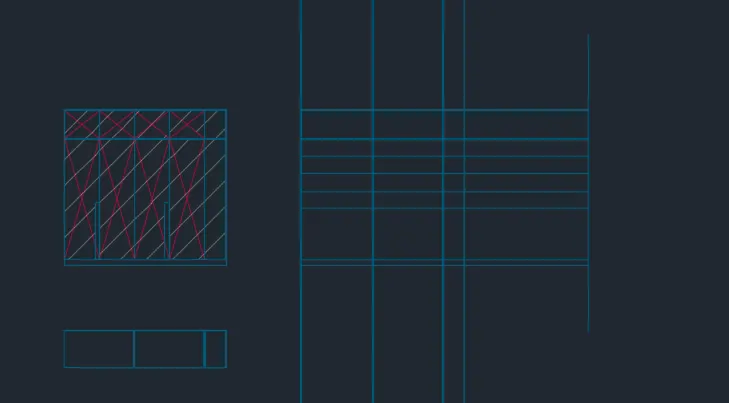
- Use the trim Command to trim the Unnecessary Lines
- Select the Transparent Layer Set to Current Layer Draw diagonal Line as Per Given diagram
- Project the Horizontal Lines and Press enter
- Give the Command of XL and Select V and press enter
- Specify the Point and Give the Command of Offset and Give the Offset Length as 630 and press Enter
- Select the Vertical Lines and give the Command of Offset and press enter Give the Offset Length as 12 Press enter press Esc.,
- Select the Horizontal Lines and give the Command of Offset and press enter Give the Offset Length as 520 Press enter press Esc.,
- Select the Horizontal Lines and give the Command of Offset and press enter Give the Offset Length as 1180 Press enter press Esc.,
- Select the Horizontal Lines and give the Command of Offset and press enter Give the Offset Length as 30 Press enter press Esc.,
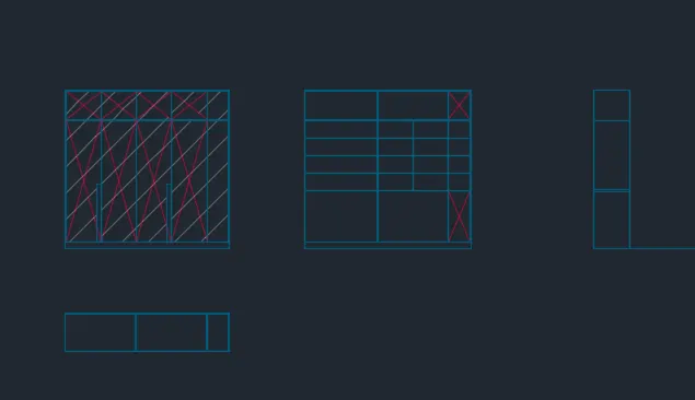
- Project the Horizontal Lines and Press enter
- Give the Command of XL and Select V and press enter
- Specify the Point and Give the Command of Offset and Give the Offset Length as 630 and press Enter
- Select the Vertical Lines and give the Command of Offset and press enter Give the Offset Length as 12 Press enter press Esc.,
- Select the Horizontal Lines and give the Command of Offset and press enter Give the Offset Length as 520 Press enter press Esc.,
- Select the Horizontal Lines and give the Command of Offset and press enter Give the Offset Length as 300 Press enter press Esc.,
- Select the Vertical Lines and give the Command of Offset and press enter Give the Offset Length as 12 Press enter press Esc.,
- Select the Horizontal Lines and give the Command of Offset and press enter Give the Offset Length as 300 Press enter press Esc.,
- Select the Vertical Lines and give the Command of Offset and press enter Give the Offset Length as 12 Press enter press Esc.,
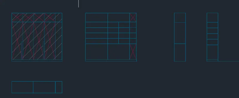
- Project the Horizontal Lines and Press enter
- Give the Command of XL and Select V and press enter
- Specify the Point and Give the Command of Offset and Give the Offset Length as 365 and press Enter
- Select the Vertical Lines and give the Command of Offset and press enter Give the Offset Length as 12 Press enter press Esc.,
- Select the Vertical Lines and give the Command of Offset and press enter Give the Offset Length as 12 Press enter press Esc.,
- Select the Horizontal Lines and give the Command of Offset and press enter Give the Offset Length as 520 Press enter press Esc.,
- Select the Vertical Lines and give the Command of Offset and press enter Give the Offset Length as 12 Press enter press Esc.,
- Select the Horizontal Lines and give the Command of Offset and press enter Give the Offset Length as 1180 Press enter press Esc.,
- Select the Horizontal Lines and give the Command of Offset and press enter Give the Offset Length as 12 Press enter press Esc.,
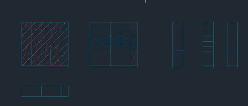
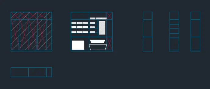
- Select the Layer tool From the Ribbon tab and Create a New Layer as text and Dimensions, select the Colour as White
- Specify the Starting and End Point Give the Dimensions
- Select the Annotate tab and Select the Multi Leader and Set the Settings to as Per Requirement and Specify the Point and Enter the text Press Enter
Result:-
Q.2
Aim:- Draw the floor plan By Using Auto Cad
Procedure:-
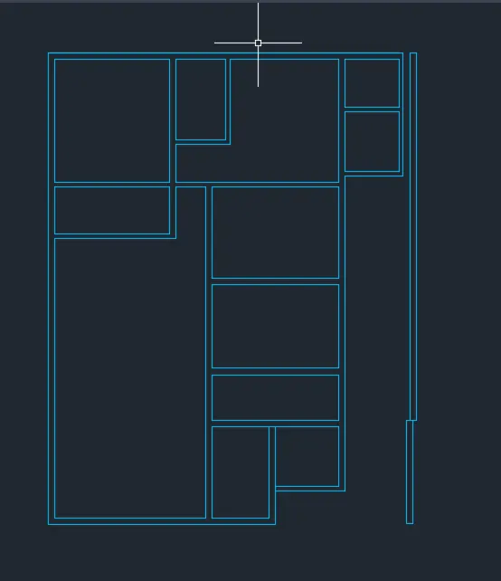
- Give the Command of X Line and Select the Vertical Line Option and Specify the Point as Corner Point of a Work Space Press Enter
- Give the Command of X Line and Select the Horizontal Line Option and Specify the Point as Bottom of a Work Space Press Enter

- Give the Command of offset Press Enter Select the Horizontal Line Specify the Offset Distance as per Require Standards Press Enter
- Repeat the Offset Command Until the Outer Walls are Formed
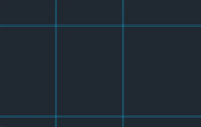
- Give the Offset Command and Press Enter and Give the Offset Length as 9710 and promote the Offset Press Enter
- Give the Offset Command and Press Enter and Give the Offset Length as 150 and Promote the Offset Press Enter
- Repeat the procedure as Per Requirement By Using Given Figure
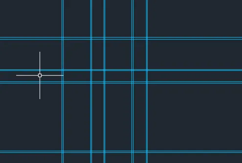
- Give the Command of Trim to Unnecessary Lines to Trim
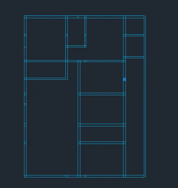
- Give the offset Command and Press Enter Specify the Offset Distance as 3200 and Press Enter
- Specify the bottom line and to offset to Press Enter
- Give the offset Command and Press Enter Specify the Offset Distance as 230 and Press Enter
- Specify the Previously Ofsted line to offset to Press Enter
- Give the offset Command and Press Enter Specify the Offset Distance as 1600 and Press Enter
- Specify the Previously Ofsted Line to Press Enter
- Give the offset Command and Press Enter Specify the Offset Distance as 230 and Press Enter
- Specify the Previously Ofsted line to offset to Press Enter
- Give the Command of Trim Used to trim Unnecessary Lines Press Enter and Esc.,
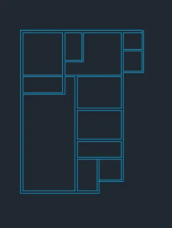
- Use the trim Command to trim Unnecessary lines
- Use the Fillet Wherrever its Required
- Use Line tool From ribbon Tab
- Draw a Vertical Line From the Right Corner of Required Length Press Esc.,
- Type Offset in the Command Bar and Press Enter
- Specify the Offset distance as 230 and select Vertical Line Press Esc.,
- Again Draw a Vertical From a Offset Distance Using Line tool From the ribbon Tab
- Type Offset in the Command press Enter
- Specify the offset Distance as 230 and select the Vertical Line Press Esc.,
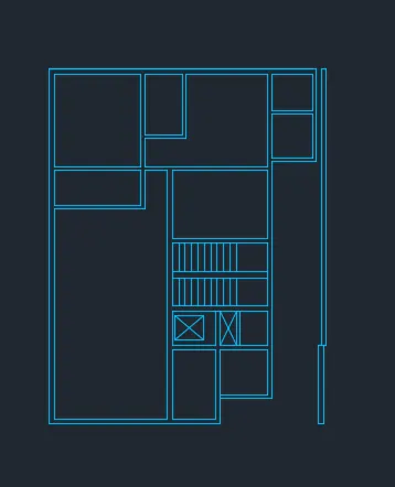
- Draw a Line of Required Length Using Line tool From the Ribbon tab to Create a Staircase.
- In the Centre Space Draw a Rectangle Using Rectangle Command and Press Enter Specify the dimension as Per Required Press Enter
- Give the Command of Offset and Prompt and press enter
- Since the Thread Length is 300mm, Specify the Offset Distance as 300
- Give the Command of DIM Line and press enter to Do Multiple Offsets Required Flight is Obtained
- Repeat the Same Procedure on the Downward Direction also
- Click on the Layer Tool From the Ribbon Tab
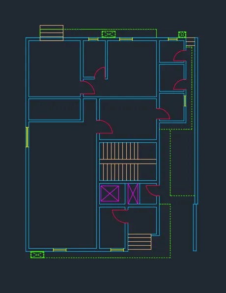
- In the layer Settings, Create a Layer to indicate Dash Lines
- Select the Line Type and Then Click Load
- From the Displayed Line Type Select the Suitable Line type and Press enter
- Select the Line tool From the Ribbon tab
- Draw the Line According to the Figure Given
- Click on the Layer Tool From the Ribbon Tab
- Create the Layers According the Drawing pars and Press Enter
- Draw a Doors For Required Length
- Specify the Windows and Ventilators according to the Figure Given
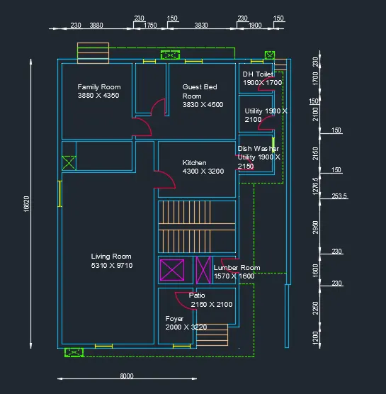
- Select the Annotate tab and Select the Multiline text
- Place the Pointer Where its Required and Click
- Give the Text as per Figure Given and Draw and Press Ok
Reuslt:-
Q.3
Aim:- Create the Kitchen Layout By Using Auto Cad
Procedure:-
- Give the Command of X Line in the Command Bar Press Enter
- Select V Specify the Corner of the Working space and Press Enter
- Give the Command of X Line in the Command Bar Press Enter
- Select H Specify the Corner of the Working space and Press Enter
- Give the Command of Offset and Press Enter
- Give the Offset Distance as 230 Offset the Both Horizontal and Vertical Lines Press enter
- Give the Command of Offset and Press Enter
- Give the Offset Distance as 4300 Offset the Vertical Line Press enter
- Give the Command of Offset and Press Enter
- Give the Offset Distance as 3200 Offset the horizontal Line Press enter
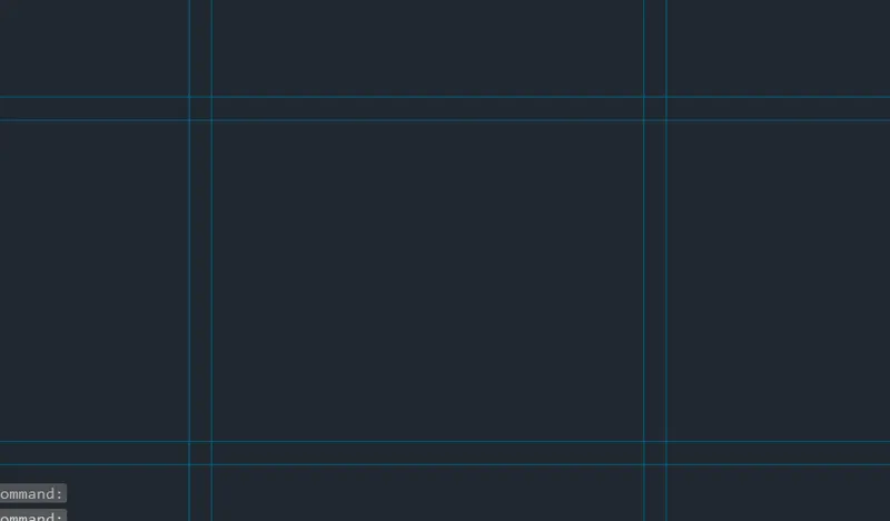
- Use the Trim tool From the Ribbon Tab and Trim the Unwanted Lines
- Trim Portion Required to Draw the Door
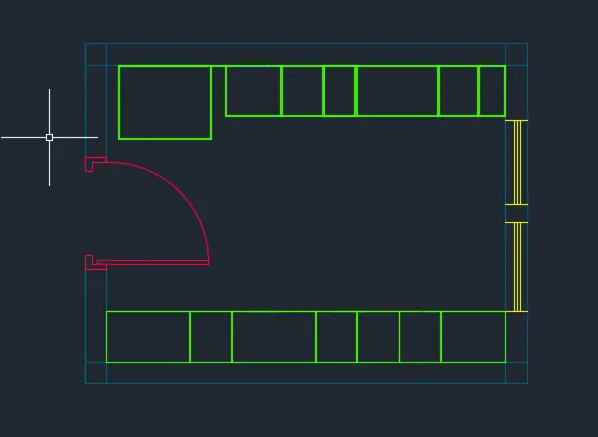
- Select arc tool From the Ribbon Tab and select Start and End Direction Press enter
-
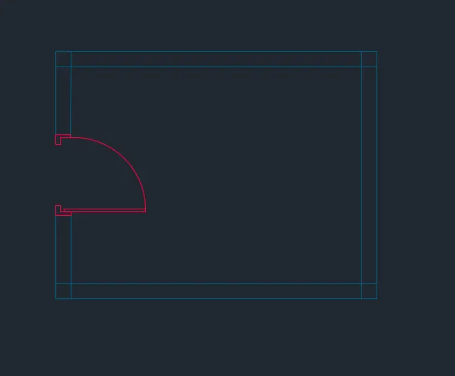
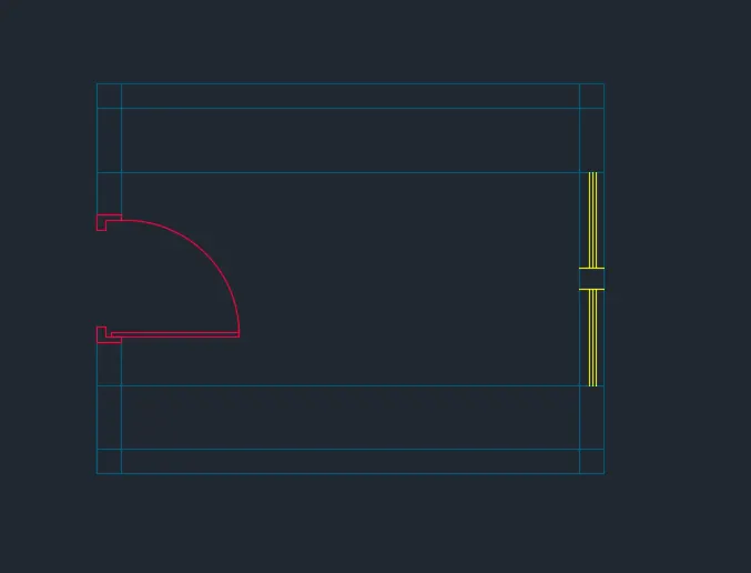
- Give the Command of offset and Press Enter Specify the Offset Distance as 600 on Both Horizontal Sides Press Esc.,
- Select the Line tool From the Ribbon Tab and Draw Position of Window Use Rectangle tool tool From the Ribbon tab and to Draw Separation
- Again, Use the Line tool to Draw the Next Window
-
- Draw a Line tool From the Ribbon tab and Specify the Length as 800 in -y Direction and Press Enter
- Draw a Line tool From the Ribbon tab and Specify the Length as 100 in X Direction and Press Enter
- Draw a Line tool From the Ribbon tab and Specify the Length as 500 in -y Direction and Press Enter
- Draw a Line tool From the Ribbon tab and Specify the Length as 650 in X Direction and Press Enter
- Draw a Line tool From the Ribbon tab and Specify the Length as 550 in -y Direction and Press Enter
- Draw a Line tool From the Ribbon tab and Specify the Length as 450 in X Direction and Press Enter
- Draw a Line tool From the Ribbon tab and Specify the Length as 550 in -y Direction and Press Enter
- Draw a Line tool From the Ribbon tab and Specify the Length as 300 in X Direction and Press Enter
- Draw a Line tool From the Ribbon tab and Specify the Length as 550 in -y Direction and Press Enter
- Draw a Line tool From the Ribbon tab and Specify the Length as 900 in X Direction and Press Enter
- Draw a Line tool From the Ribbon tab and Specify the Length as 550 in -y Direction and Press Enter
- Draw a Line tool From the Ribbon tab and Specify the Length as 550 in X Direction and Press Enter
- Draw a Line tool From the Ribbon tab and Specify the Length as 300 in X Direction and Press Enter
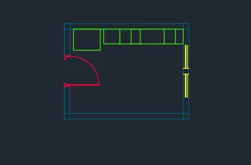
- Draw a Line tool From the Ribbon tab and Specify the Length as 550 in -y Direction and Press Enter
- Use offset command and Specify the Length as 965 in X Direction and Press Enter
- Draw a Line tool From the Ribbon tab and Specify the Length as 550 in -y Direction and Press Enter
- Use offset command and Specify the Length as 600 and Press Enter
- Draw a Line tool From the Ribbon tab and Specify the Length as 550 in -y Direction and Press Enter
- Use offset command and Specify the Length as 865 and Press Enter
- Draw a Line tool From the Ribbon tab and Specify the Length as 550 in -y Direction and Press Enter
- Use offset command and Specify the Length as 865 and Press Enter
- Draw a Line tool From the Ribbon tab and Specify the Length as 550 in -y Direction and Press Enter
- Use offset command and Specify the Length as 865 and Press Enter
- Draw a Line tool From the Ribbon tab and Specify the Length as 550 in -y Direction and Press Enter
- Use offset command and Specify the Length as 865 and Press Enter
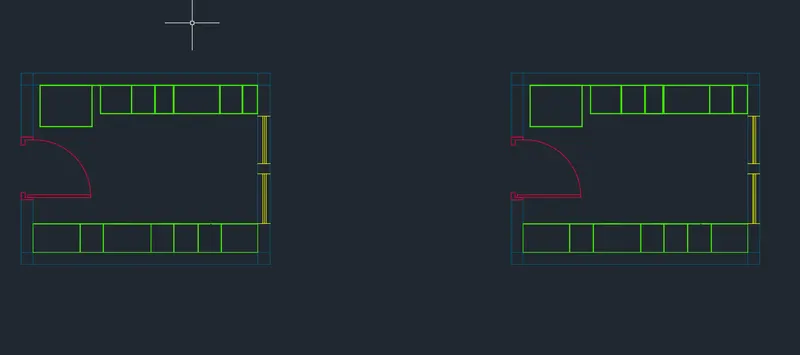
- Select the Entire object in the Work Space
- Type Copy in the Command Bar Press enter
- Select Bottom Left Corner as Base Point
- Move the Copy the object and in the Positive X Direction and Place it
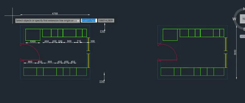
- Specify the Dimensions tool From the Ribbon tab and Press enter Specify the Starting Point and Ending Point
- Move the Cursor to Adjust the Position
- Press C and Click Continue and Select the Base Point and Dimensioning has to Continue
- Move the cursor to next Point and Click to Display the Dimensions
- Repeat the Procedure to Display the Dimension’s
- Select the Text tool From the Ribbon Tab and Select Multiline Text and press enter
- Give the Text as Kitchen 4300 X 3200 Press Ok
- Copy the Text and Move Cursor to X Direction and Paste in another Layout Plan
- Click Ok
Q.4.
Aim:- Sketch the column details Using Auto Cad
Procedure:-
- Give the Command of Rectangle REC enter Specify the Starting Point Give the Length and Breadth Required Size
- Press Enter.,
- Select the Line tool From Ribbon tab and
- Draw a Vertical Line Inside the Rectangle as Per the Figure
- Press Esc
- Draw a Horizontal Line Inside the Rectangle as Per the Figure
- Press Esc
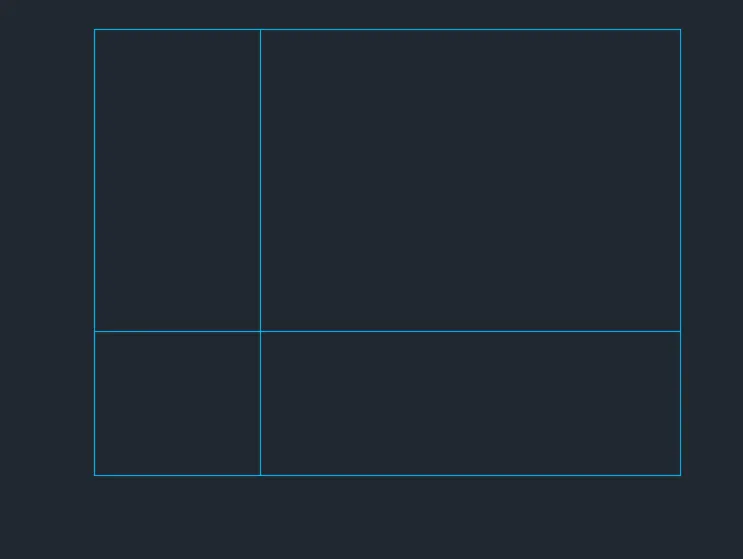
- Type Offset Command Prompt and Specify the suitable Offset Distance
- Offset the Same Line for Two more times
- Use trim Tool From Ribbon Tab to trim Unwanted Lines
- Copy the Object and Select array Option Give No as 3 Press Enter
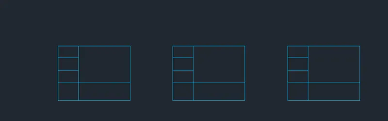
- Select Text tool from the Ribbon Tab
- From the Dropdown Line List Single Line Text
- Now keep the pointer in the Left Box and Click as Per the Alignment Required
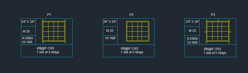
- Type the text as 24” x 24” Click on the Place Where the Text has to be entered
- Type the text as M25 Click on the Place Where the Text has to be entered
- Type the text as 4-25 12-16 Click on the Place Where the Text has to be entered
- Type the text as 8@8CRS (1 Set of 5 Strips) Click on the Place Where the Text has to be entered
- Repeat the Same procedure in Remaining Patrs also. Press Ok.
Result:-
Q.5
Aim:-
Draw the Raft Layout as shown in the Figure. By Using Auto Cad
Procedure:-
- Type units in the Command bar Press Enter
- In the tab Select units as Architectural and Insertion scale as Inches
- Click Ok
- Select the Line type tool From the Ribbon Tab
- Click Load
- From the Dialogue Box Select the Long Dash Short Dash and Click Ok
- Select line tool From Ribbon Tab Specify the Starting pony in Work Space
- Draw a Line Length 53’5” In the Vertical Direction Press Ok
- Specify the Starting pony in Work Space
- Draw a Line Length 26’9” In the Vertical Direction Press Ok
- Type offset Command Prompt and Press enter
- Specify the offset Distance as 53’5”
- Select horizontal Line to offset
- Press Esc.,
- Type offset Command Prompt and Press enter
- Specify the offset Distance as 26’9”
- Select Vertical Line to offset
- Press Esc.,
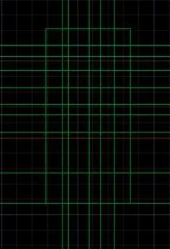
- Type X line in the Command Bar Press enter
- Press V in the Command prompt and Place line
- Type X line in the Command Bar Press enter
- Press H in the Command prompt and Place line
- Type offset Command Prompt and Press enter
- Specify the offset Distance as 5’6”
- Select Xl line to Offset
- Press Esc
- Type offset Command Prompt and Press enter
- Specify the offset Distance as 2’
- Select Previously offsetted Vertical Line to offset Press Esc.,
- Type offset Command Prompt and Press enter
- Specify the offset Distance as 7’
- Select Previously offsetted Vertical Line to offset Press Esc.,
- Type offset Command Prompt and Press enter
- Specify the offset Distance as 4’
- Select Previously offsetted Vertical Line to offset Press Esc.,
- Type offset Command Prompt and Press enter
- Specify the offset Distance as 4’6”
- Select Previously offsetted Vertical Line to offset Press Esc.,
- Type offset Command Prompt and Press enter
- Specify the offset Distance as 5’7.5”
- Select Previously offsetted Vertical Line to offset Press Esc.,
- Similarly in the horizontal direction Use offset tool
- Type offset Command Prompt and Press enter
- Specify the offset Distance as 10’4.5”
- Select Horizontal Xl line to Offset
- Press Esc
- Type offset Command Prompt and Press enter
- Specify the offset Distance as 13’10.5”
- Select Previously offsetted Horizontal Line to offset Press Esc.,
- Type offset Command Prompt and Press enter
- Specify the offset Distance as 5’9”
- Select Previously offsetted Horizontal Line to offset Press Esc.,
- Type offset Command Prompt and Press enter
- Specify the offset Distance as 3’9”
- Select Previously offsetted Horizontal Line to offset Press Esc.,
- Type offset Command Prompt and Press enter
- Specify the offset Distance as 5’7.5”
- Select Previously offsetted Horizontal Line to offset Press Esc.,
- Type offset Command Prompt and Press enter
- Specify the offset Distance as 5’10.5”
- Select Previously offsetted Horizontal Line to offset Press Esc.,
- Type offset Command Prompt and Press enter
- Specify the offset Distance as 3’7.5”
- Select Previously offsetted Horizontal Line to offset Press Esc.,
- Type offset Command Prompt and Press enter
- Specify the offset Distance as 5’7.5”
- Select Previously offsetted Horizontal Line to offset Press Esc.,
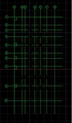
- Select the Circle tool From the Ribbon Tab
- Draw a small Circle By Specifying Centre and Radius Randomly Press Esc.,
- Select the Circle and Copy in the Command Prompt
- Place the Copied Object in Places Where its Required as per the Figure
- Select Text Tool From the Ribbon tab
- From Drop Down Select Single Line Text
- Place the Cursor the inside the Circle to Insert Text
- Repeat the Procedure until Same
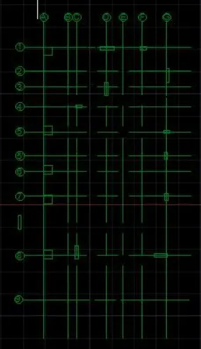
- Select Rectangle tool From the Ribbon tab
- Specify the starting Point and select Dimensions
- Enter length as 24” and Width as 24”
- Press Esc
- Select Rectangle tool From the Ribbon tab
- Specify the starting Point and select Dimensions
- Enter length as 9” and Width as 24”
- Press Esc
- Select Rectangle tool From the Ribbon tab
- Specify the starting Point and select Dimensions
- Enter length as 9” and Width as 18”
- Press Esc
- Place the Rectangle’s in the Grid Points as Given Figure
- To Draw the Footing Marking Use Line tool From the Ribbon Tab
- From the Face D1 Column Draw a Line of Length 2’6” on either Direction
- Connect the line to Form the Footing
- Similarly Draw the Footing For other Grid Columns
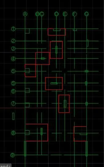
- To Draw the L Shaped Combined Footing Use line tool From the Ribbon Tab
- Draw a line of Length 2’6” in the Downward Direction
- Specify the next Point to Give the Length as 7’1.5” In horizontal Direction and press Enter
- Specify the next Point to Give the Length as 6’1.5” In Vertical Direction and press Enter
- Specify the next Point to Give the Length as 2’6” In horizontal Direction and press Enter
- Press Esc
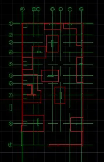
- Select the Hatch tool From Ribbon Tab press Enter
- From the hatch dialogue Box Select Hatch Indicating Concrete
- Select as per Required Visibility
- Place the Cursor Where hatch is to Be Done and Click
- Again Click on Hatch tool From the Ribbon tab
- From the hatch dialogue Box Select Hatch Indicating Brick Work
- Select as per Required Visibility
- Place the Cursor Where hatch is to Be Done and Click
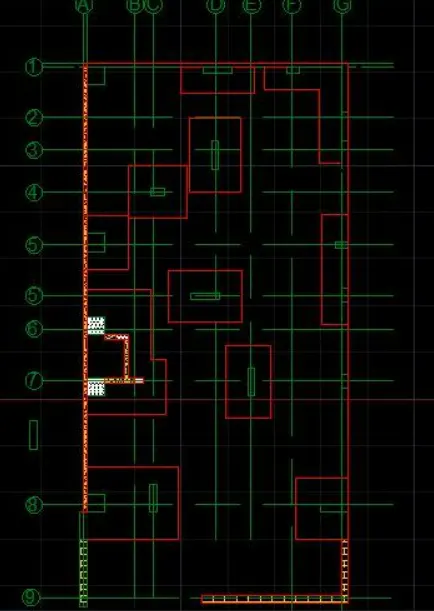
Result:-