Creating a Wardrobe detailed drawing, Floor Plan, Kitchen Layout and Column Detail using AutoCad
1.
AIM
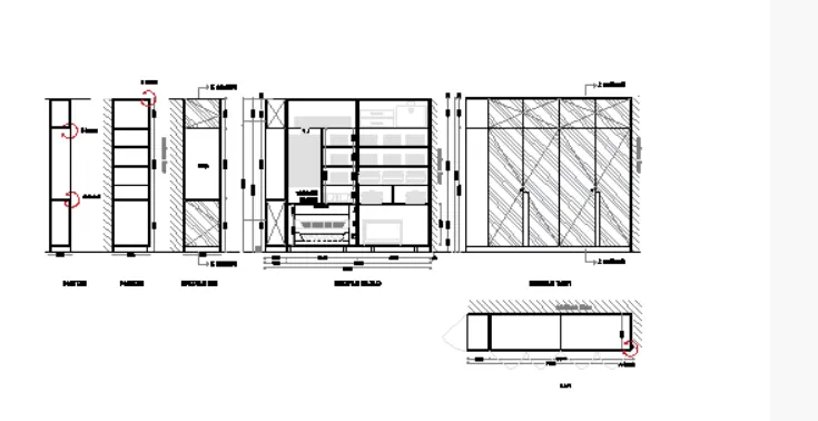
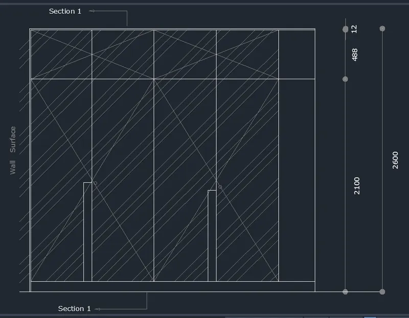
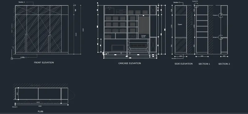
Draw the elevation and details of a wardrobe as shown in the Figure below. After sketching, you need to provide the dimensions and text with the use of layers. Use proper text styles and dimension methods to document it. Also, assume dimensions, wherever needed.
INTRODUCTION:
PROCEDURE:
- Go to AutoCAD application.
- Open a New Sheet.
- Set Unit using UN command as Engineering and Millimeter.
- Use XLine command and draw a Vertical and Horizontal line.
- Then Use OFFSET command and offset the vertical Xline for 12mm and divide it for four parts with the calculated dimension.

- Then again use Offset command and offset the horizontal line for 100mm, 2000mm,488mm and 12mm.

- Then use Trim command and trim the all excess lines.
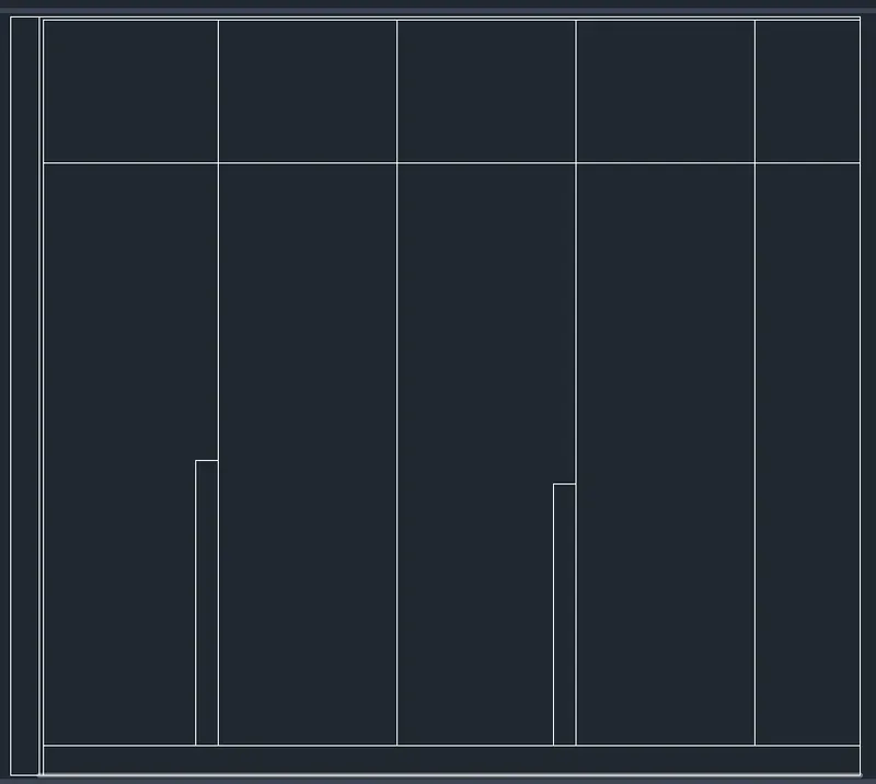
- Then use Hatch command then hatch the closed areas as above diagram.
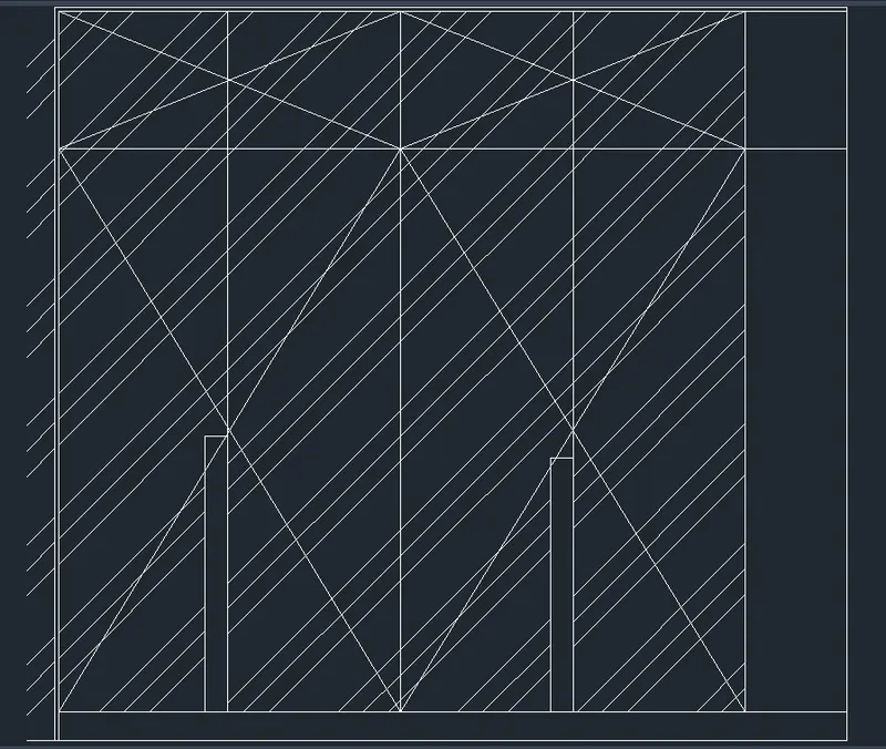
- Now use the Dim Linear command for measuring Dimensions.
- Use QLeader command for the arrows.
- And MText for the texts.
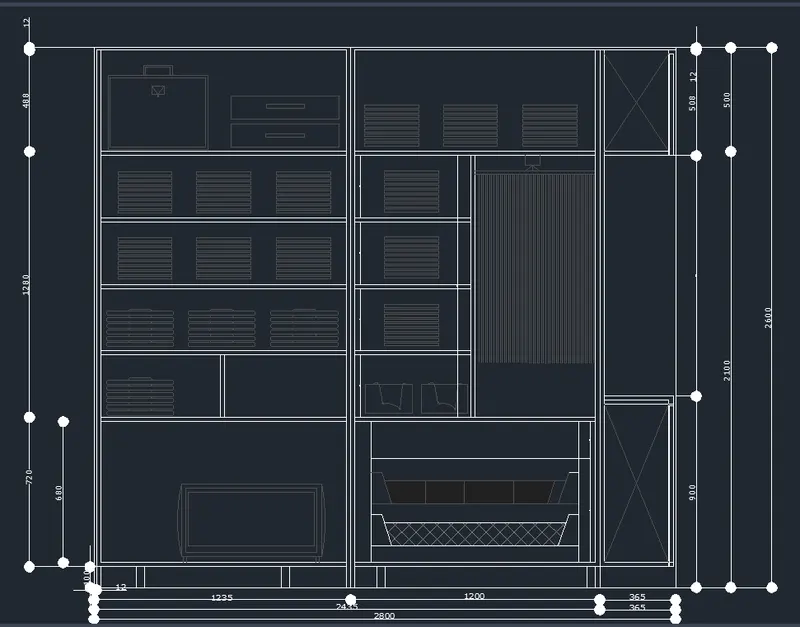
- It is the FRONT ELEVATION.
- In the Same diagram of Front Elevation again draw a Xline in Hortizontal and Verical direction.
- And use Offset command and Offset it for 100mm in vertical direction and 12mm in horizontal direction and 1235 in horizontal direction and 1200mm in Horizontal direction and again 365mm in the same direction.
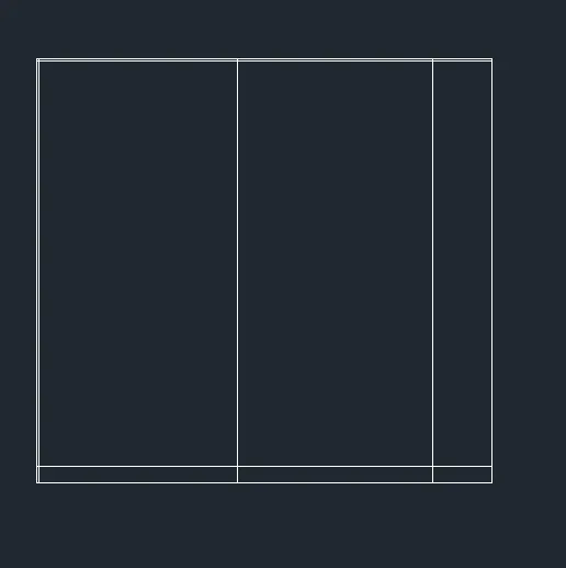
- Use Offset command and offset the line for 900 in vertical direction and 1200mm in vertical direction and 508mm and 12mm in vertical direction.
- Use Line command and draw the furnitures and use copy command for copy and place it in another place.
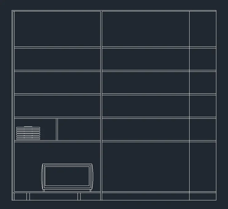
- Use COPY command and copy the furniture and place it in various places where you need.
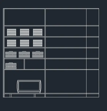
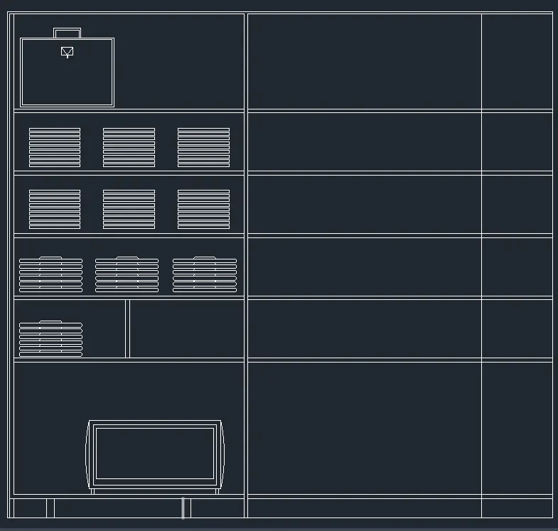
- Use the Line, Rec, Arc and Offset command for the furnitures.
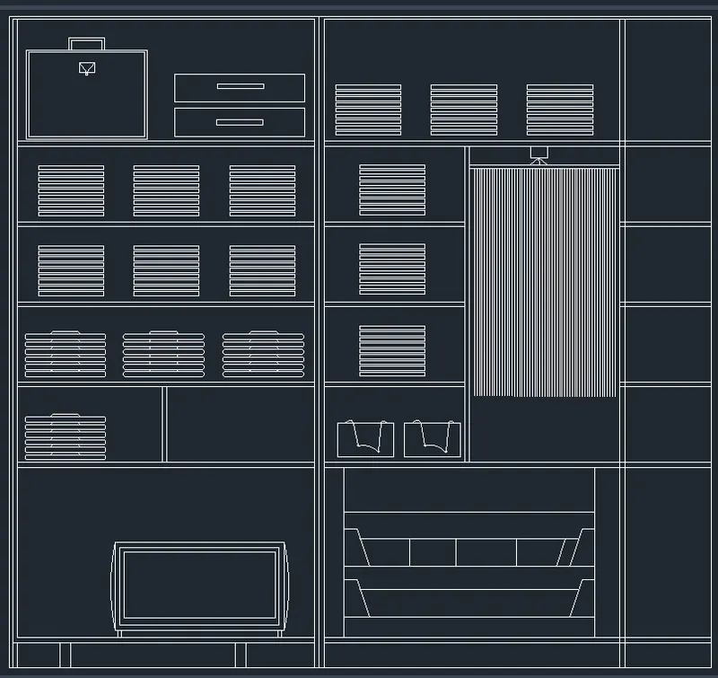
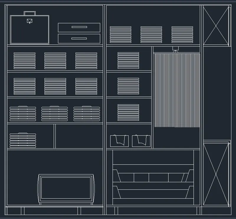
- Go to Properties for changing Colors of the furnitures.
- And use Hatch command where you need.
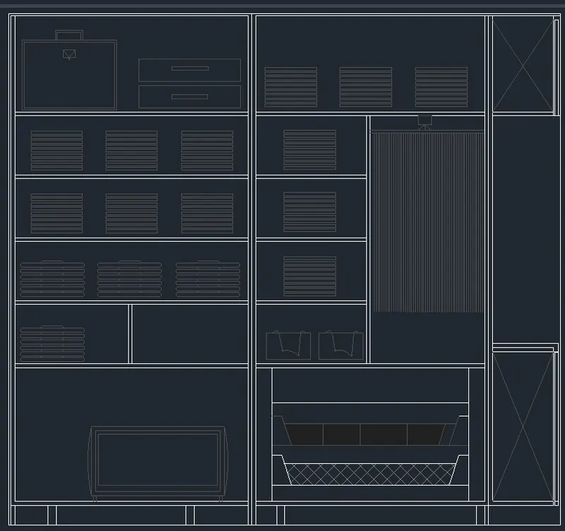
- Now use DimLinear for the dimensions.
- Use MText command for the Texts.
- This is the CARCASE ELEVATION.
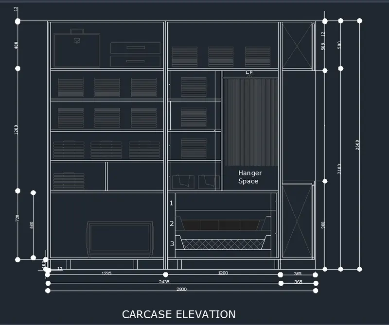
- In the Same diagram of Front Elevation again draw a Xline in Hortizontal and Verical direction.
- And use Offset command and Offset it for each 630mm in horizontal direction.
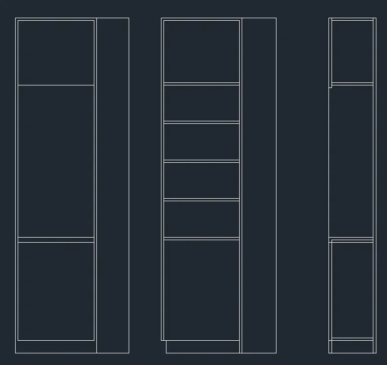
- Use DimLin for the Dimensions.
- And use MText for the Texts.
- Then use Hatch command where you need.
- And go to properties if you need to change color.
- This is SIDE ELEVATION.
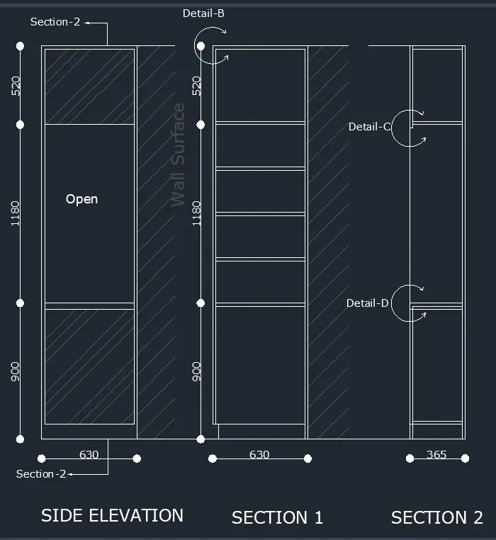
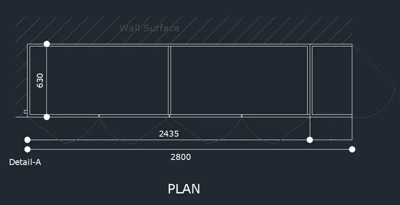
- Use XLine command and draw horizontal and vertical lines.
- Offset the Horizontal line for 630mm in vertical direction.
- And Offset the Vertical line for 2435mm and 365 in horizontal direction.
RESULT:
2.
AIM:
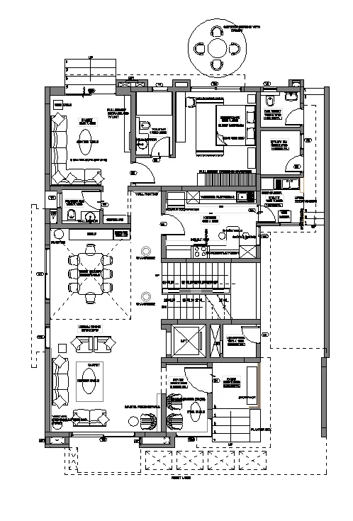
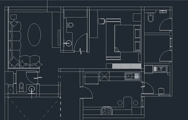
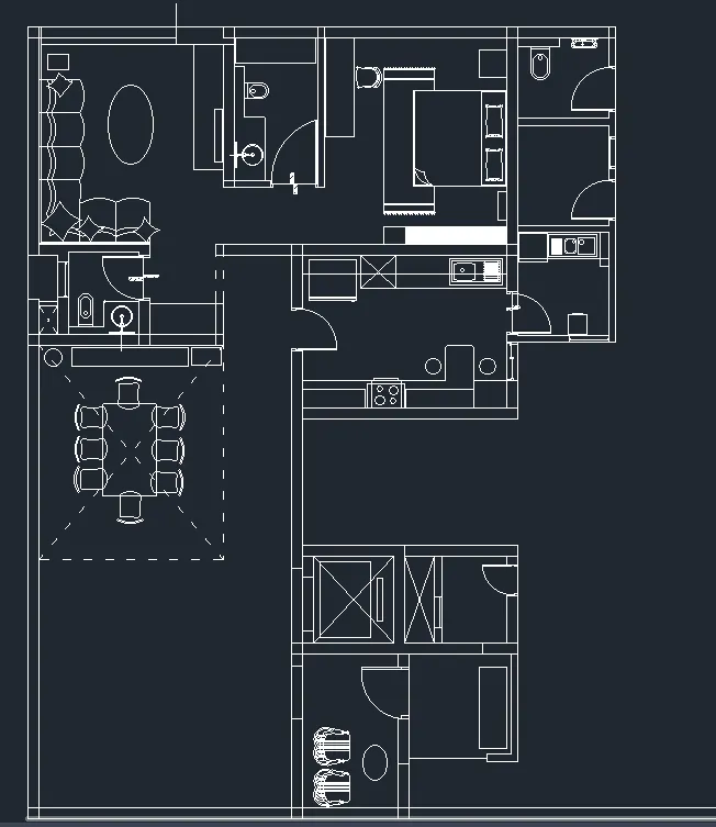
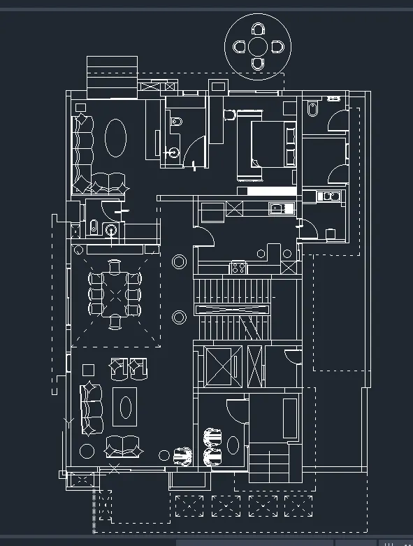
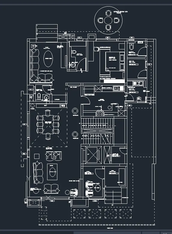
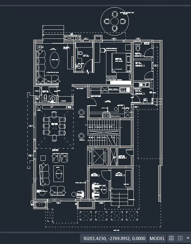
Draw the floor plan as shown in the Figure. Use the proper drafting tools to sketch the plan. Do not hatch or draw the furniture. You need to draw the floor plan with the following:
Note: You can also import the Floor_Plan.pdf into your current drawing and start working on the project. You need to scale the imported pdf file using reference option. All dimensions are in mm.
- Walls (Exterior and Interior)
Wall Thickness: Exterior Wall- 230mm, Interior Wall: 150 mm (Wherever Required)
- Doors and Windows: Assume the size of the doors and window.
2.1 Stairs: Tread-300mm, Riser-150mm
INTRODUCTION:
PROCEDURE:
- Go to AutoCAD application.
- Open a New Sheet.
- Set Unit using UN command as Engineering and Millimeter.
- Use XLine command and draw a Vertical and Horizontal line.
- Use Offset command and draw the outline borders of Exterior wall 230mm and Interior wall 150mm.
- Use ACAD_ISO03W100 for LineType where needed.
- And Use Circle and Fillet command for the Wall Mirror.
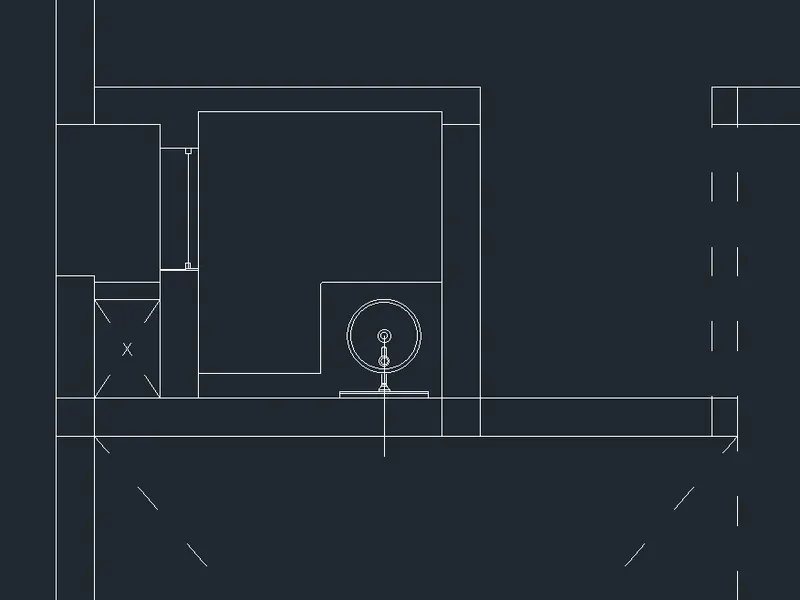
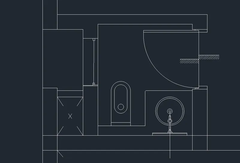
- Use Arc command for the Door.
- And Hatch command where needed.
- And for Toilet use Arc and Circle command.
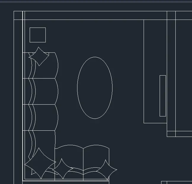
- Use Ellipse for Center Table.
- And Use Rec and Rotate command for the cushion.
- And Line and Arc for the Sofa.
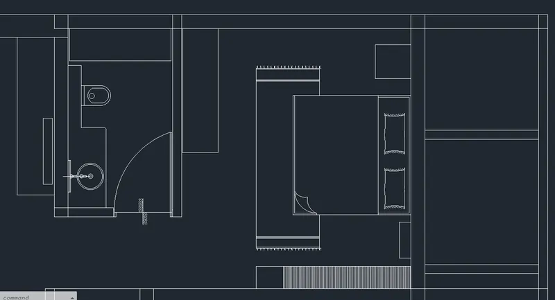
- Use Array command for the carpet corners and pillows.
- Use rec and line command for the bed.
- Use Rec, Circle and Fillet commands for the Kitchen.
- Use Line command where mostly needed.
- Use circle command for the Kitchen HOB.
- Use the Arc and Mirror command for the Single Seater.
- Use copy command for the dining table.
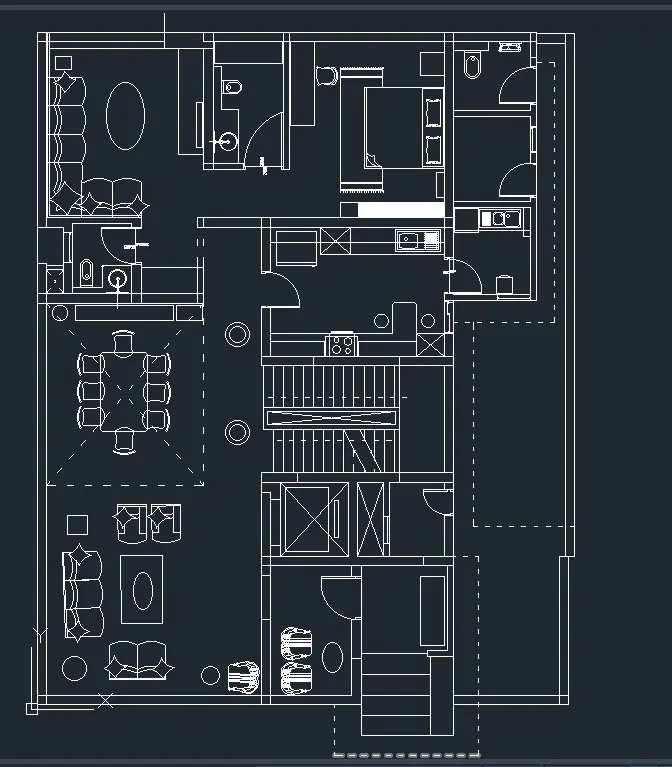
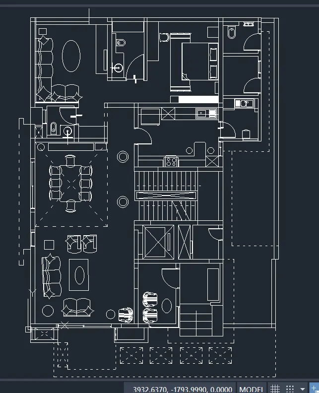
- Use MText for the Texts and Use Roman.shx style.
- Use Dim Lin for the Dimension.
- Use Hatch command for the Exterior walls.
- And go to properties to change the color.
RESULT:
Q3.
AIM:
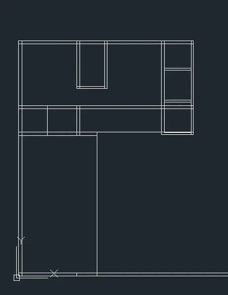
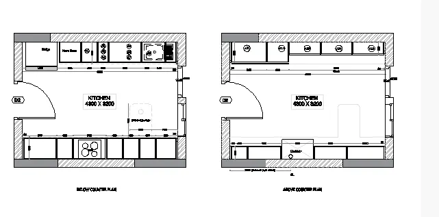
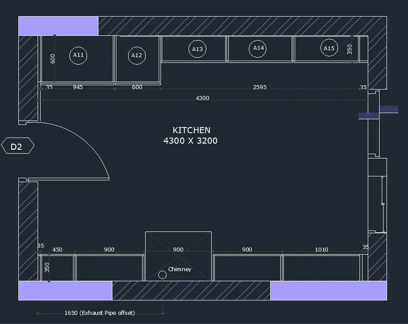
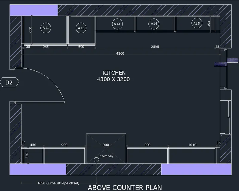
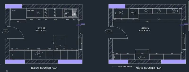
Create the Kitchen Layout as shown in the Figure below. Also, use proper dimension techniques to dimension the kitchen layout. Also, insert text wherever required. All dimensions are in mm.
INTRODUCTION:
PROCEDURE:
- Go to AutoCAD application.
- Open a New Sheet.
- Set Unit using UN command as Engineering and Millimeter.
- Use XLine command and draw a Vertical and Horizontal line.
- Use Offset command and offset the Hor and Ver lines for 300mm for exterior wall.
- The offset the vertical line for 35mm, 900mm, 450mm, 900mm,450mm, 450mm, 450mm, 560mm in Horizontal direction in the lower part.
- The offset the vertical line for 35mm, 1000mm, 450mm, 300mm, 900mm, 625mm, 320mm and 35mm in the upper part.
- Use Line command for the sink and use circle command for the required areas.
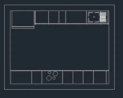
- Now use the Hatch command and hatch it for the exterior walls.
- Go to the properties for changing the line type and line color.
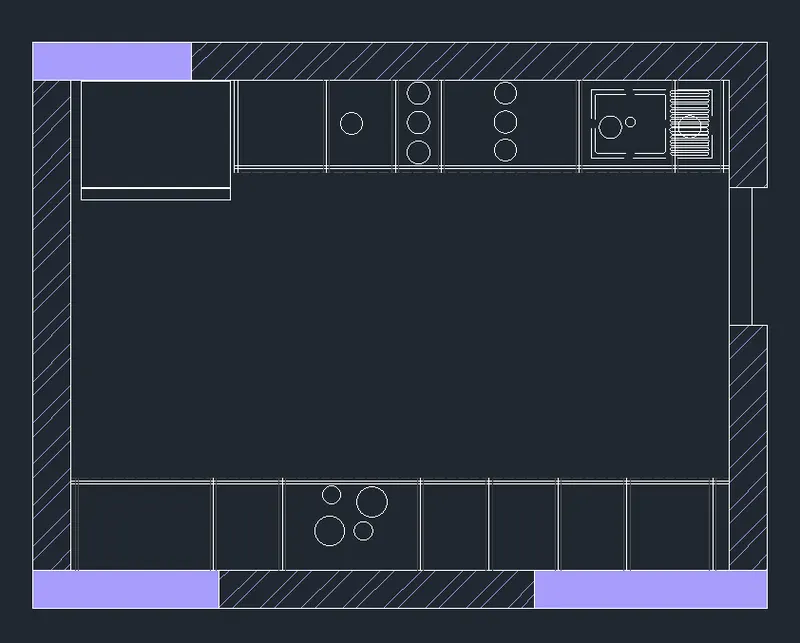
- Use Arc command for the Door.
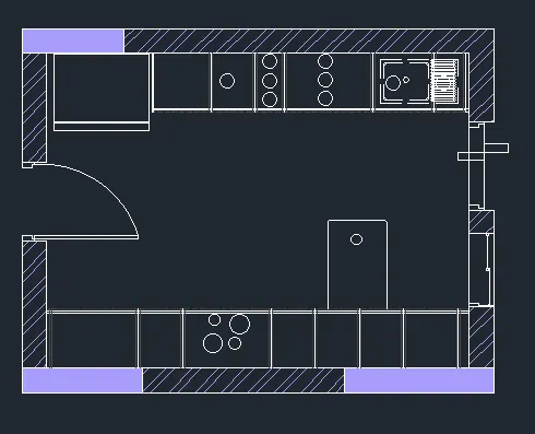
- Use DimLin for the dimensions.
- And MText for the Texts.
- Go to properties for changing the colors for dimensions.
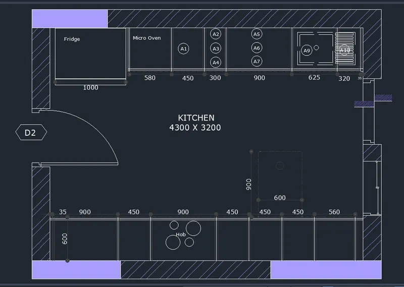
- In the second drawing change the inner parts dimensions and sizes.
- Use Properties to change the colors or edit something.
- Use MText for texts.
RESULT:
Q4.
AIM:
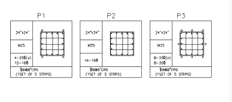
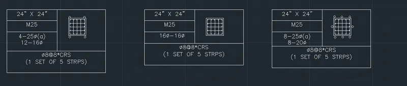
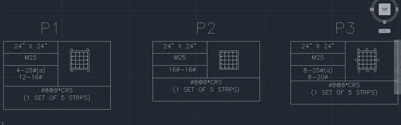
Sketch the column details as shown in Figure. Insert dimensions and text in the figure. Refer to the bar sizes from the schedule.
8mm ---- 0.31 Inches
25mm--- 1 inches
16mm—0.62 inches
INTRODUCTION:
PROCEDURE:
- Go to AutoCAD application.
- Open a New Sheet.
- Use Table command and create a table with 2 column and 4 rows.
- Then create the bar diagrams using line and circle command.
- Use the MText command for texts.
- Then copy the bar diagrams and paste it in the table.
- Merge the table if you want.
- Create the 3 as shown in the diagram.
RESULT:
Q 5.
AIM:
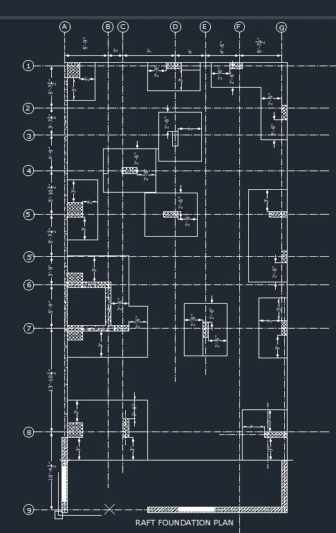
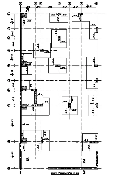
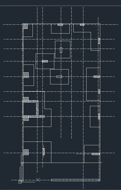
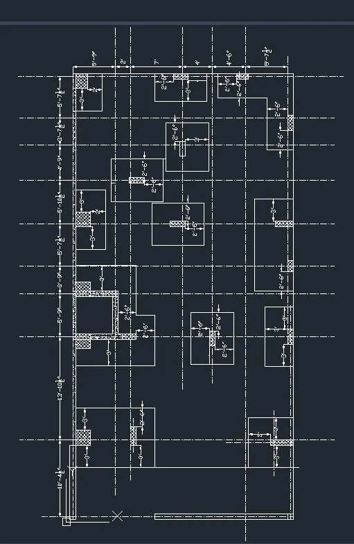
Draw the Raft Layout as shown in the Figure. Assume the column size as per your knowledge. You can take the sizes as: 24”x24”, 9” x 24”, 9” x 18”, and 9’ x 24”. You can import the raft_foundation.pdf to ensure the missing dimensions.
INTRODUCTION:
PROCEDURE:
- Go to AutoCAD application.
- Open a New Sheet.
- Set Unit using UN command as Architectural and inches.
- Use XLine command and draw a Vertical and Horizontal line.
- Use the LineType as Centerline type.
- And the Exterior wall is 9" wall.
- Draw the interior part with given dimensions.
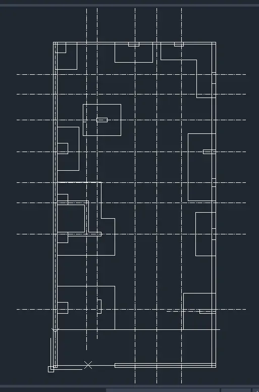
- Use the Hatch command and hatch the parts where needed.
- Use DimContinue for the outer side dimensions.
- Use Dim Lin for Interior dimensions.
- Use the MText for the texts.
RESULT: