Creating a Wardrobe detailed drawing, Floor Plan, Kitchen Layout and Column Detail using AutoCad
AIM :
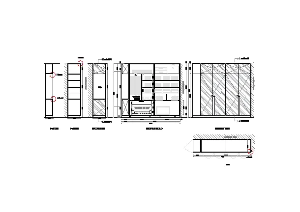
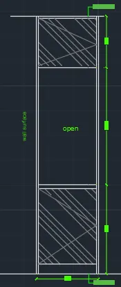
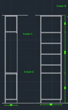
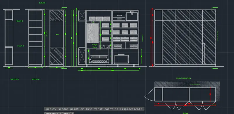
Draw the elevation and details of a wardrobe as shown in the Figure below. After sketching, you need to provide the dimensions and text with the use of layers. Use proper text styles and dimension methods to document it. Also, assume dimensions, wherever needed.
INTRODUCTION:
- Drawing the elevation and details of a wardrobe in autocad by using the layer properties for dimension and text and using various command like Draw tools like Line, Rectangle, Polyline, And with the help modify tools like Move, Copy, Strecth, Offset, and using Ortho and osnap
PROCEDURE:
Step-1 : Plan
- Use the line command by using L enter and select the first point at any point in the drawing area
- Slect the first point draw the line towards the E direction with the distance of 2345mm
- And select the next point towards the N direction with a distance of 630mm
- And select the next point towards the W direction with a distance of 2345mm
- And select the next point towards the S direction with a distance of 630mm and close the command
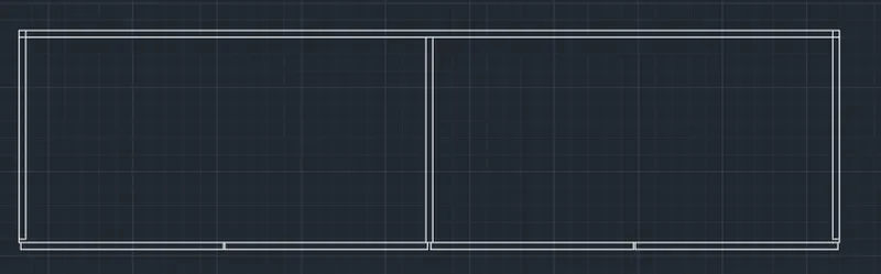
- Use the offset tool and do offset with a disrance of 20mm in the inside of rectagle drawn by the line command as shown in the below drawing
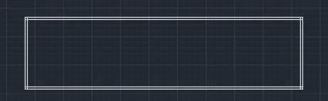
- Use the centerline command take the center line of the both in side offset lines of the drawing and enter and the center line is formed
- Use the line command by using L enter draw the reference line on the center and erase the center line
- Use the offset command by using o enter and do offset to the reference line towards E and W direction with the distance of 10mm and erase the refernce line and shown by the below drawing
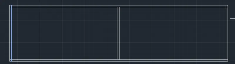
- Use the offset command by using O enter select the mid point of the bottom line and do offset to the distance of 10 towards W & E direction and erase the center line and trim the unwanted lines
- So again do this process of the both enter and ad agian to the enter to make doors at both sides so as shown in below drawing
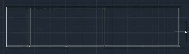
- Use the Line command by using L enter and draw the line from the corner point of the line L enter towards the W direction with the didtance of 365 and enter
- and copy the line and select the start point of the line with the distance of 630 towards the N direction and enter
- And use the offset command by using o enter select the both horizontal lines and vertical lines and do offset towards the S and N and Wdirection with a distance of 20mm and enter so shown in the below drawing
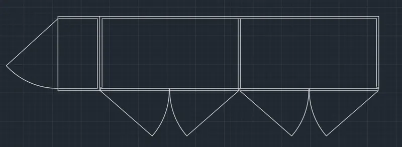
- Use the circle command and draw a circle with the start point is first corner of the door and and end point of the door and enter
- uUse the line command by using L enter and select the cornor point of the door and draw the line with the 270 degrees line attach to the circle and enter
- Use the Trim command by suing TR double enter and trim the unwanted lines and enter
- And select the door and use mirror command and take the refenece point as midpoint and take reference of mirror object towards the E direction and enter
- And use the copy command by usinf CO enter and and starting point is cornor point of the door and enter past to the remaing doors
- Repeat this same circle process W side door as shown in below drawing
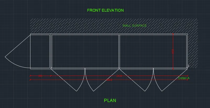
- Use the layer properties and add a layer with the name of Text with the colour is 80
- And add a another layer with the name of dimension with the colour is 10 and enter
- Use the dimension layers to mark the dimensions
- Name the Text with the sinle line text.
- Use the copy command and copy the total top line and copy towards the N direction with some refernce distance and enter
- Use the offset command and do offset to the line with a distance of 100 towards N direction and enter
- And again do offset to the offseted line 2000 towards the north ditection and enter
- And again do offset to the offseted line 418 towards the north ditection and enter
- And again do offset to the offseted line 12 towards the north ditection and enter
- And use the line command joint the both ends with the line
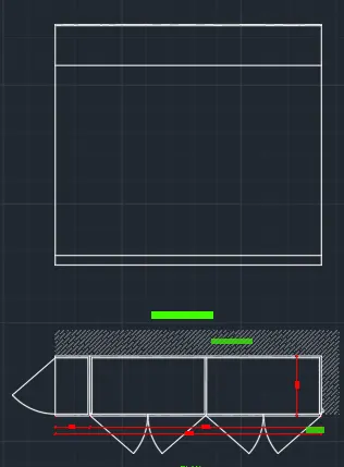
- Use the offset command take the offset line E direction vertrical line and do offset E direction eith a distance of 345 and enter
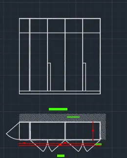
- And again do offset at a distance of 25 and enter towards E direction
- And again do offset at a distance of 600 and enter towards E direction
- And again do offset at a distance of 5 and enter towards E direction
- And again do offset at a distance of 600 and enter towards E direction
- And again do offset at a distance of 10 and enter towards E direction
- And again do offset at a distance of 600 and enter towards E direction
- And again do offset at a distance of 5 and enter towards E direction
- And again do offset at a distance of 600 and enter towards E direction and close the command
- use the tr double enter and trim the unwanted lines and enteras shown in below drawing
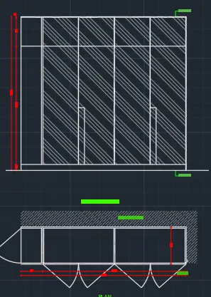
- Use the hatch command and hatch the required area and enter
- use the dimensions and required text and also use the leader text dor mentioning the section
- Use the offset command and do offset at a distance of 600 and and continues the command
- and do offset at a distance of 10 and again offset at adistance of 20
- and again do offset at a distance of 1233 and again do offset towards the E direction at a distance of 20
- and do offset to the bottom horizontal line at a distance of 100 and again offset to 20
- and again do offset to 20 line towards N direction with a distance 600 and enter
- and again do offset to 600 line towards N direction with a distance 20 and enter
- and again do offset to 20 line towards N direction with a distance 300 and enter
- and again do offset to 300 line towards N direction with a distance 20 and enter
- and again do offset to 20 line towards N direction with a distance 300 and enter
- and again do offset to 300 line towards N direction with a distance 20 and enter
- and again do offset to 20 line towards N direction with a distance 300 and enter
- and again do offset to 300 line towards N direction with a distance 20 and enter
- and again do offset to 20 line towards N direction with a distance 300 and enter
- and again do offset to 300 line towards N direction with a distance 20 and enter
- and again do offset to 20 line towards N direction with a distance 300 and enter
- so like this we have do all those
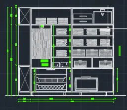
- use the offset command by the distance of 300 and enter
- again do offset at adistance of 12 enter and again do offseet at a distance of 630 and again do offset at a distance of 12 and enter
- Again use the line command by using L enter draw a line
RESULT:
AIM:
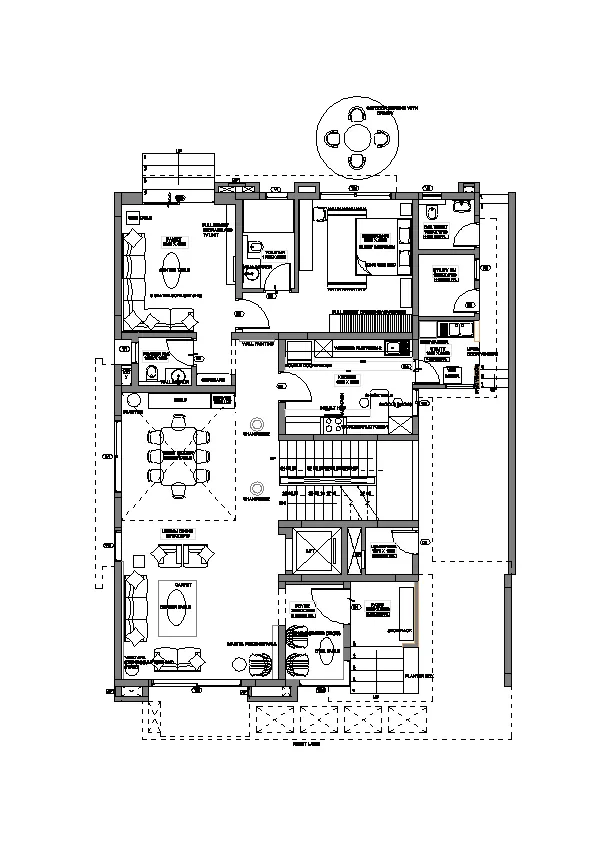
Draw the floor plan as shown in the Figure. Use the proper drafting tools to sketch the plan. Do not hatch or draw the furniture. You need to draw the floor plan with the following:
Note: You can also import the Floor_Plan.pdf into your current drawing and start working on the project. You need to scale the imported pdf file using reference option. All dimensions are in mm.
- Walls (Exterior and Interior)
Wall Thickness: Exterior Wall- 230mm, Interior Wall: 150 mm (Wherever Required)
- Doors and Windows: Assume the size of the doors and window.
2.1 Stairs: Tread-300mm, Riser-150mm
- Insert Text wherever required
- Insert the dimensions using proper dimension techniques
INTRODUCTION:
- To draw the plan we need kmow about the all measurements of the carpet area to mention the specify dimensions and i am using the layer properties and seperate for text and dimension and few of the commands use line offset fillet champer trim erase stretch and many all commands
PROCEDURE:
- Use the line command and draw the required lines
- and do offset at the distance s and draw as spereate and make to the drawing a complete the drawing
- use the circle and trim command for the doors
- use the line types and line properties fot the remining lines
- Use the layer properties of the text and dimensions and enter
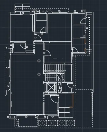
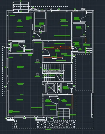
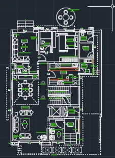
- Draw a furniture separately for completing the drawing
- Like sofa, queen sixe and king size bed and washrooms and toiltes etec
RESULT:
AIM:
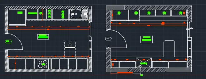
Create the Kitchen Layout as shown in the Figure below. Also, use proper dimension techniques to dimension the kitchen layout. Also, insert text wherever required. All dimensions are in mm.
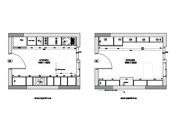
INTRODUCTION:
- While drwing the kitchen flat form we need to clarfy the all dimension as wu assume and draw using theautocad by using the layer properties for dimension and text and using various command like Draw tools like Line, Rectangle, Polyline, And with the help modify tools like Move, Copy, Strecth, Offset, and using Ortho and osnap
PROCEDURE:
Step-1
- Use the construction line command by using XL enter and draw a line Horizontal and vertical direction and enter
- And do offset for both horizonta line and vertical line with a distance of 150 and enter
- and again use the offset command and do offset to the horizontal 150 offseted line towards the N direction at a distance of 3200 and again offset to that line to 150 and enter
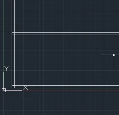
- and again use the offset command and do offset to the vertical 150 offseted line towards the E direction at a distance of 4300 and again offset to that line to 150 and enter
- And use the trim command and trim the unwanted lines and enter
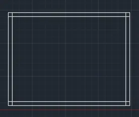
- use the offset command and do offset to horizontal 150 offseted line towards the N direction with a distance of 1000 and again do offset at a distance of 900 from the 1000 offseted line
- Use the offset command and do offseted to vetical 150mm line towards the E direction with a distance of 1000 and enter
- and again do offset to 20mm line towards the E direction with distance
- and again do offset to 600mm line towards the E direction with distance
- and again do offset to 450mm line towards the E direction with distance
- and again do offset to 20mm line towards the E direction with distance
- and again do offset to 300mm line towards the E direction with distance
- and again do offset to 20mm line towards the E direction with distance
- and again do offset to 900mm line towards the E direction with distance
- and again do offset to 20mm line towards the E direction with distance
- and again do offset to 1045mm line towards the E direction with distance
- And adain do offset to the top interior horizontal line towards the S direction at a distance 600 and enter
- and again do offset to 30mm line towards the N direction with distance
- and again do offset to 20mm line towards the N direction with distance and showm in the below drawing
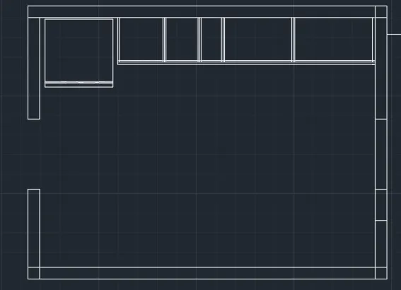
- use the offset command and do offset to horizontal 150 offseted line towards the N direction with a distance of 35 and again do offset at a distance of 880 from the 35 and contioue offseting tho the ofsseted line
- and again do offset to 20mm line towards the E direction with distance
- and again do offset to 20mm line towards the E direction with distance
- and again do offset to 430mm line towards the E direction with distance
- and again do offset to 20mm line towards the E direction with distance
- and again do offset to 20mm line towards the E direction with distance
- and again do offset to 880mm line towards the E direction with distance
- and again do offset to 20mm line towards the E direction with distance
- and again do offset to 20mm line towards the E direction with distance
- and again do offset to 430mm line towards the E direction with distance
- and again do offset to 20mm line towards the E direction with distance
- and again do offset to 20mm line towards the E direction with distance
- and again do offset to 430mm line towards the E direction with distance
- and again do offset to 20mm line towards the E direction with distance
- and again do offset to 530mm line towards the E direction with distance
- and again do offset to 20mm line towards the E direction with distance
- And adain do offset to the bottom interior horizontal line towards the S direction at a distance 600 and enter
- and again do offset to 30mm line towards the N direction with distance
- and again do offset to 20mm line towards the N direction with distance and showm in the below drawing
- and trim the unwanted lines and enter as shown in the below drawing
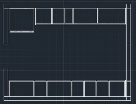
- And use the remaing drawing iteams asusal and add the dimension and text with sepeerate layer properties and enter
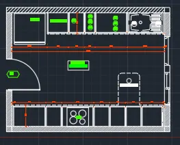
- Use the copy coammnd selet the all walls
- and us the same process for above the kitchen level.
RESULT:
AIM:
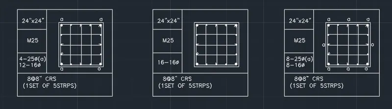
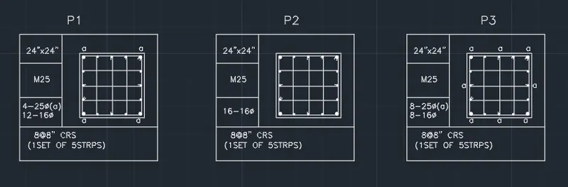
Sketch the column details as shown in Figure. Insert dimensions and text in the figure. Refer to the bar sizes from the schedule.
8mm ---- 0.31 Inches
25mm--- 1 inches
16mm—0.62 inches
INTRODUCTION:
- For drawing the deatils of strctural columns we need to give the text and hatch to show the dia of the bars and mention in the deatils by using commands
PROCEDURE
Step-1
- Change the units to decimals to Engineering and precision 0'-0.0" and interaction scale Inches and click on OK
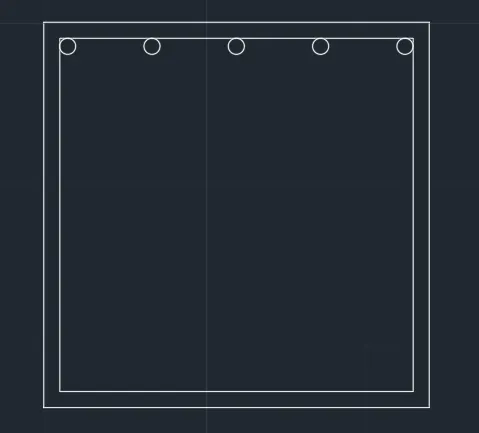
- Draw a rectangle by using REC enter with 24",24" and enter
- Use the offset command and do offset at inside with the distance of 1" and enter
- Draw a circle with the D of 1" and enter
- And place to the top left corner of the offseted circle and enter
- Use the copy command A enter for the array type and enter number of entries is 5 and enter fit option to fit between the center as shown in below drawing
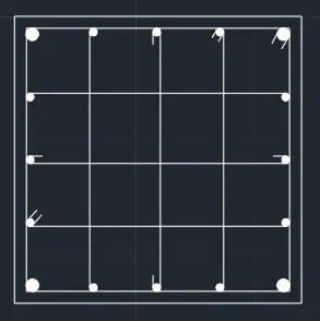
- Use the same process and vertical direction to and some are the 16mm bars and enter
- And use the line command by using L enter to draw the strips and enter as shown in below drawing
- and hatch the bars with hatch pattern and enter
- Draw a refernce rectangle by using REC enter and make to do the table as we required and enter
- And use the multiline text with the height of 2" amd font is on romans and enter
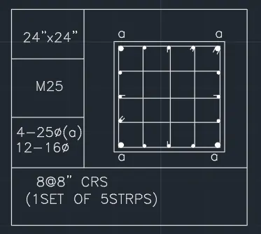
- Use the same table to modify the remaining exsisting drawings to speed up the work
RESULT:
AIM:
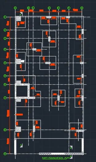
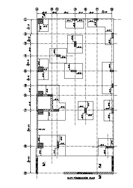
Draw the Raft Layout as shown in the Figure. Assume the column size as per your knowledge. You can take the sizes as: 24”x24”, 9” x 24”, 9” x 18”, and 9’ x 24”. You can import the raft_foundation.pdf to ensure the missing dimensions.
INTRODUCTION:
- For drawing the deatils of strctural columns placeing we need to give the text and hatch to show and mention in the deatils by using commands
PROCEDURE:
- Firstly draw a grid and with the spacing provided by the pdf
- and drea a required rectangle by using rec and enter
- and place it to the required area
- hatch the rectangle and hatch with the symbols
- and use the layer properties of the dimensions and text by seperate
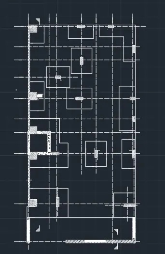
RESULT: