Creating a Wardrobe detailed drawing, Floor Plan, Kitchen Layout and Column Detail using AutoCad
DRAWING OF ELEVATION AND DETAILS OF A WARDROBE
Aim:
Drawing of elevation and details of a wardrobe in AutoCAD using various tools
Procedure:
Setting up Workspace
- Open AutoCAD and press ctrl+N with the metric system to open a new drawing
- Type UNIT and set units as a decimal with inputs in millimeters
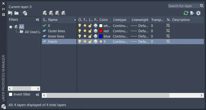
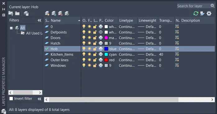
- Type LAYER command to open layer box and create various layers for drawing. Requisite needed layers will be created during the course of the drawing
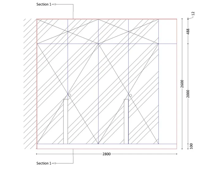
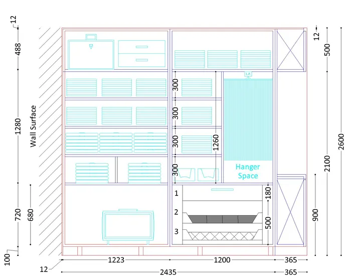
Drawing of Front Elevation
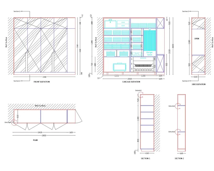
- Draw RECTANG of size 2800x2600 mm for the size of the cabinet
- Use EXPLODE to disintegrate the rectangle
- OFFSET bottom line by 100 mm for legs of the cabinet
- OFFSET right side by 365mm for rightmost part
- Marking 12mm top and left side thickness by OFFSET
- TRIM to remove excessive lines
- OFFSET left side inner corner by 1223 mm for first closet and further OFFSET by 1200 mm for further closet
- Divide both closets into half for showing their gates
- OFFSET by 488 mm for the top section of the closet
- Mark Cross Lines in gates with visibility of 50
- Marking of lockset using CIRCLE and RECTANG below it for both gates
- Draw wall surface using HATCH command on left side
- HATCH the front part also with transparency of 50
- Marking of Section 1 marks in drawing using QLEADER command
- Use TEXT to type Section 1 with a text height of 50
- Measure DIM of front and show on right side
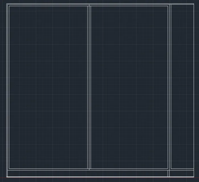
Drawing of Carcase Elevation
- Draw a RECTANG of 2800 x 2600 and EXPLODE it
- Making left and top 12mm thick boundary using OFFSET
- OFFSET by 100 for bottom legs
- OFFSET by 365 mm for the right portion
- OFFSET by 1200 mm for the middle part of the cabinet
- The thickness of the inner wall of wardrobe to be 20mm and mark using OFFSET command for outer boundaries
- Use TRIM command to remove excessive lines due to OFFSET command
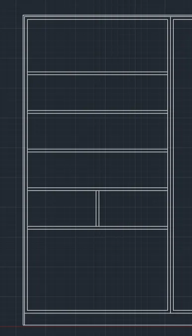
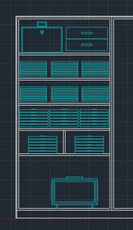
Draw parts in the left-most part of the cabinet
- OFFSET by 680mm for TV space
- OFFSET by 24 mm for thickness
- COPY this part and place at 5 places at 300 mm distance each using ARRAY command
- Create two equal sections in the first 300 mm portion using the LINE command
Creating objects in left most cabinet
- Create TV in the bottom-most part of the cabinet using various commands like LINE, RECTANG, FILLET, ARC
- Create goods in bottom 300 mm parts using LINE, COPY, FILLET commands
- Similarly, put the objects in top 300 mm parts and topmost part
- Use the BLOCK command to make the object as a single object
Draw parts in the middle part of the cabinet
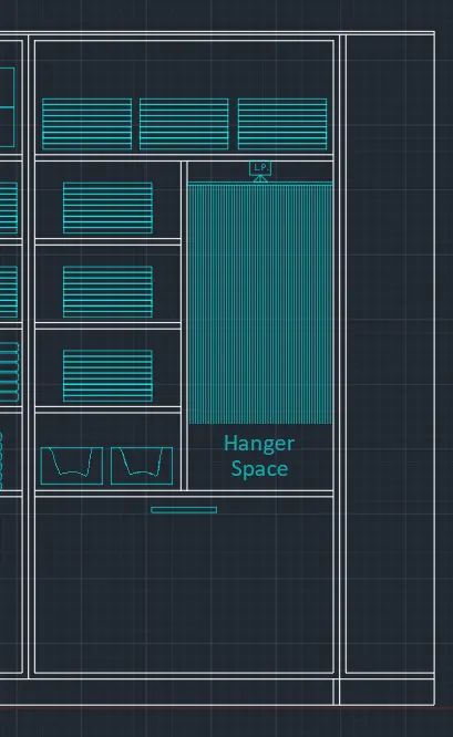
- Make bottom 680 mm space and top 500 mm using OFFSET command with the thickness of 24 mm
- Divide the middle portion into 2 parts vertically using the DIVIDE command on line
- Make 300m parts in left division
- COPY similar objects from the left part and place middle portions as shown in the drawing
- Use LINE and OFFSET command for showing clothes in hanger space
- Use TEXT command for placing texts
- Draw objects in the bottom 300 mm section using RECTANG and SPLINE command
- Use the RECTANG command to create a small rectangle in the bottom part
Drawing object in the bottom section of the middle part
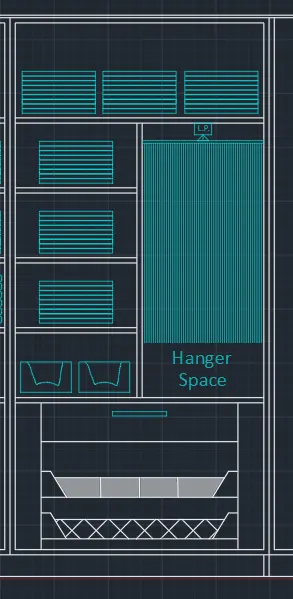
- OFFSET from both sides by 120 mm
- OFFSET bottom line by 50 mm
- Use LINE command for making side trapezoids
- COPY the trapezoid and place it above it as shown
- Draw a LINE at 180 mm distance
- Use the HATCH command to fill the parts as in the drawing
Draw objects in the rightmost part of the cabinet
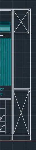
- OFFSET top line 500mm
- Make a wall of 20 mm bottom and right side of top portion using OFFSET command
- Draw cross using LINE command
- For the bottom cross, First OFFSET by 900 from bottom
- Use TRIM command for cutting extra parts
- OFFSET at right and top part for 20 mm
- Use LINE command to make a cross as shown
Drawing pedestals of cabinet
- OFFSET by 50 mm in bottom 100 mm part
- COPY this and place at 4 locations as required
Making wall surface on left side
- Use MTEXT command and type wall surface with inclined to 90 degrees
Measurement of dimensions
- Type D in the command box and open dimension style box for changing measurement style
- Use DIMLIN and DIMCONT command for measurement of various dimensions
Drawing of side elevation
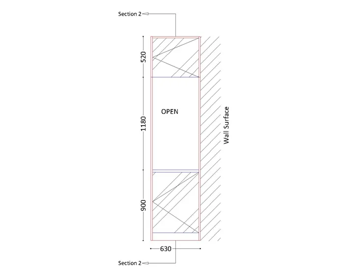
- Make a RECTANG of 630x2600 mm
- Use EXPLODE command to disintegrate it
- OFFSET bottom by 100mm for pedestals
- Make an OFFSET of 20 mm inside on all walls except the bottom
- TRIM the excessive lines
- OFFSET bottom by 900mm first line and then further OFFSET by 1180mm for top line
- Use LINE command for line in hatch portion
- Use HATCH command for hatching in the top, bottom, and right part
- Use MTEXT command and type Wall Surface and Open
- Use QLEADER command for section marking
- Use DIMLIN and DIMCONT for dimension measurements
- Use DIMBREAK for breaking dimension at intersection
Drawing of Section-1
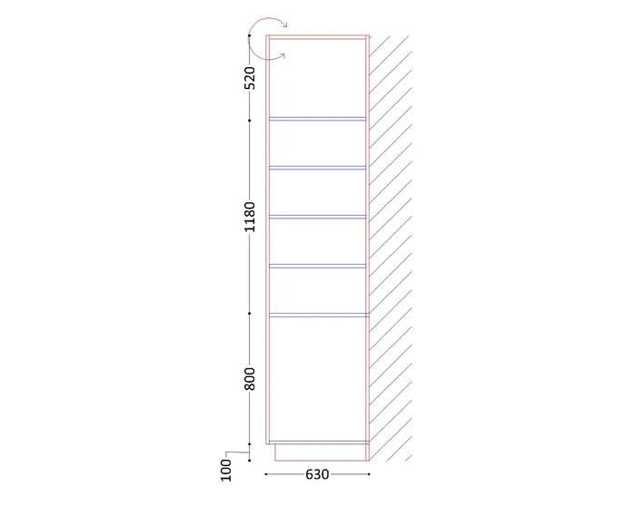
- Draw a RECTANG of 630x2600 mm and EXPLODE it
- OFFSET bottom by 100 mm
- OFFSET all side by 20 mm for wall thickness
- OFFSET by 900 from the bottom and 520 mm from top
- Start OFFSET at 300 mm from top further by making 20 mm thick wall
- Use CIRCLE for rotational arrow marking
- Use HATCH to fill right-hand side space
- Measure DIMLIN
Drawing of Section-2
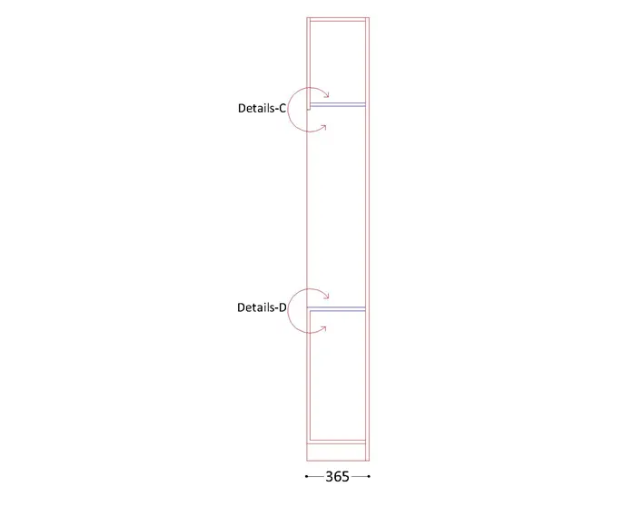
- Draw a RECTANG of 365x2600 mm and EXPLODE it
- OFFSET bottom by 100 mm
- OFFSET all side by 20 mm for wall thickness except middle half of left part
- OFFSET by 900mm from the bottom and 520 mm from top
- Use CIRCLE and LINE command to mark details c&d
- Use DIMLIN to measure
Drawing of Plan
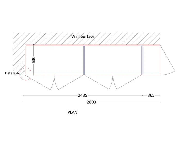
- Draw a RECTANG of 2800x630 mm and EXPLODE it
- OFFSET the right side by 365mm and mark 20 mm thickness at all sides of the rectangle
- Further OFFSET by 1200 mm and mark 20 mm thickness
- Use DIVIDE to divide bottom lines into two parts for gate marking
- Use ARC with a 30-degree angle and LINE to show the projection of all gates opening
- Use HATCH command for filling on top and left side
- Use DIMLIN to measure dimensions
Result:
DRAWING OF FLOOR PLAN
Aim:
Drawing of floor plan without drawing furniture
Procedure:
Setting up Workspace
- Open AutoCAD and press ctrl+N with the metric system to open a new drawing
- Type UNIT and set units as a decimal with inputs in millimeters
- Type LAYER command to open layer box and create various layers for drawing. Requisite needed layers will be created during the course of the drawing
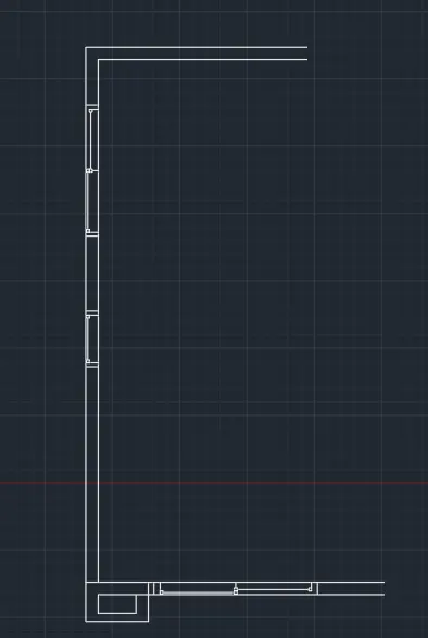
Drawing of AP on the bottom left
- Draw a RECTANG of 700X350 mm
- Use EXPLODE for disintegration purpose
- Mark wall of 230 mm on all sides except the bottom, for which 150 mm is suffice
- Use FILLET command to join all walls
Drawing of Living/Dining Room
- Draw a LINE of 9710 mm length for left side vertical wall and OFFSET it by 230 mm for thickness
- Draw a LINE of 5310mm length for the bottom horizontal wall of the living room with 230 mm thickness of the wall
- Draw a LINE of 3880 mm length for the top horizontal wall of the living room with 230 mm thickness
- Use FILLET command to join offset ends
Drawing of W1, W5, and W2 windows in living rooms
- For W1, make a cut of 2430 mm at a distance of 6425 mm from the bottom of the living room using OFFSET and TRIM tool
- Use LINE and RECTANG tool to draw the line between the window
- For W5, make a cut of 1030 mm at a distance of 4000 mm from the bottom of the living room using OFFSET and TRIM tool
- Use LINE and RECTANG tool to draw the line between the window
- For W2, make a cut of 3030 mm at a distance of 1035 mm from the left side of the living room using OFFSET and TRIM tool
- Use LINE and RECTANG tool to draw the line between the window
Drawing of bottom right-side AP
- Draw a rectangle of 1320x350 mm and make its wall by 230 mm thickness except for bottom and left side using OFFSET and FILLET command
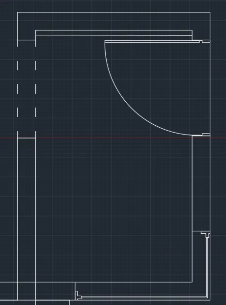
Drawing of Foyer room with windows and openings
- Draw a RECTANG of 2000x3220 mm and EXPLODE it
- To mark walls of it use OFFSET by 230 mm on all sides
- For the Left wall opening, mark the opening of 1252 at 1842 mm from the bottom wall using the OFFSET command
- Use TRIM command to cut between and put dashed LINE as required
- For D1, use the OFFSET command for the opening of 1225 mm at a distance of 1870 mm from bottom
- Use PLINE to mark a small rectangle at both ends of the gate
- Use RECTANG to make a door and use the ARC command to show door movement
- For W10, mark OFFSET at 505 mm from the left wall and mark window opening of 2145 mm encompassing 652 mm from the vertical right wall
- Use LINE to draw an inner line in the window
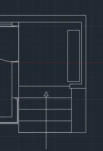
Drawing of Patio with Entry marking
- Draw a RECTANG of 2150x2100 mm and EXPLODE it
- Mark wall of 230 mm on top and 150 mm on right and bottom
- Mark bottom wall for 402 mm length only from the right side
- Mark the 5 steps of entry steps using the LINE tool up to 1500mm
- Use RECTANG for making shoe rack on the patio
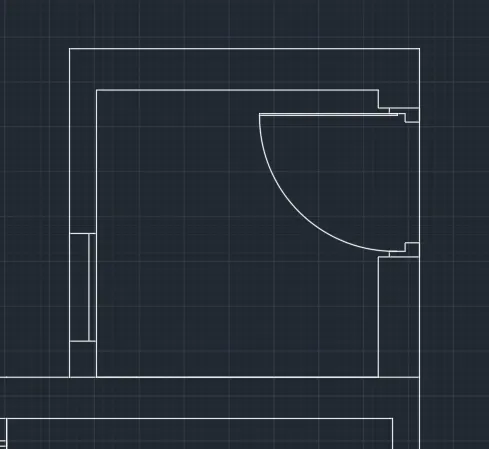
Drawing of lumber-room with D5 and Opening
- Draw a LINE of 1600mm and OFFSET it by 230 mm for the wall on the door side
- Use RECTANG for making dimensions of 1570x1600 mm and EXPLODE it
- Use OFFSET for making wall thickness of 230 on top and bottom and 150 on the left side of the wall
- For D5, mark 830 mm opening at 670 mm distance away from the bottom wall
- Use TRIM for removing excess lines
- Use PLINE, RECTANG, and ARC commands for drawing D5
- For the opening, mark the opening of 600 mm at 201 distances away from the bottom wall
- Use OFFSET command for marking opening and LINE for drawing line opening
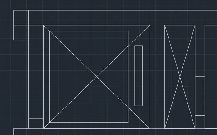
Drawing of AP back of lumber room
- Draw a RECTANG of 1600x470 mm and EXPLODE it
- Use LINE for drawing cross marking as shown
- Use OFFSET to mark wall thickness
Drawing of lift room
- Draw a RECTANG of 1650x1600 mm and EXPLODE it
- Mark wall thickness of 230 mm at left and top side using OFFSET
- Draw cross LINE
- Draw 2 RECTANG in this room for the depiction of lift and back of it
- Use OFFSET for marking of 1080 mm at 150 mm from the bottom wall
- EXTEND the top wall of the lift as shown in the drawing
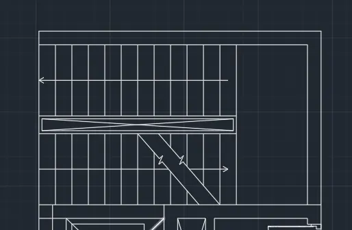
Drawing of stairs
- Draw a LINE of 2700 mm length at right end and OFFSET by 230 for wall
- Again, use LINE for making top wall and thickness of 230 mm
- Draw a RECTANG of 2700x1200 mm for mid landing and EXPLODE it
- Use RECTANG for marking the division between up and downstairs and OFFSET it inside
- Use LINE to make the cross between the divider
- Use COPY and Array to mark steps
- Use LINE to mark arrow for up and down movement
- Use LINE for mark cut in steps as shown
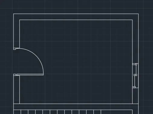
Drawing of Kitchen
- Draw a LINE of 3200 at the left end
- OFFSET it by 230 mm for wall
- For kitchen OFFSET it by 4300 and further by 230 mm for wall thickness
- For D2, Draw an opening of 1050 mm at 1075 mm distance away
- Use PLINE for door end and ARC and RCETANG for door drawing
- For W3, mark an opening of 930 at 605 distance away from the bottom wall
- Use LINE and RECTANG for marking inside window space as shown
Drawing of Utility room behind the kitchen
- Draw a LINE of 1900 mm from 1530 mm above the right wall as shown
- OFFSET it by 230 mm
- OFFSET the bottom wall by 2150 mm for the upper wall
- Mark 230 mm thickness of the right-side wall
- For D4, draw a door with an opening of 852 mm using LINE, ARC, and RECTANG command
- For the UFVC window on the bottom wall, mark the opening of 1150 mm using the OFFSET command and LINE command
- Similarly, draw UPVC door window on the right wall
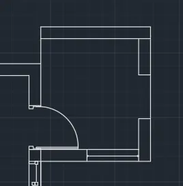
Drawing of Utility room
- Draw a RECTANG of 1900x2100 and EXPLODE it
- Mark the gate D5 at 100 mm from bottom
- Draw W9 from 295 mm from door top end
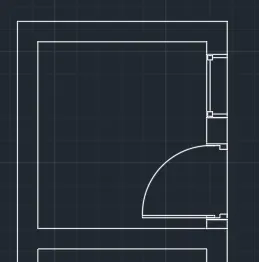
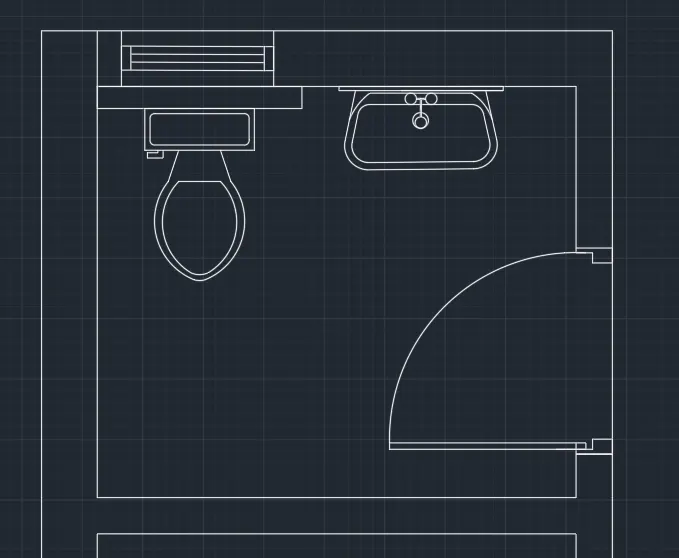
Drawing of toilet room
- Draw a RECTANG of 1900x1700 mm and EXPLODE it
- Mark wall thickness of 230 mm on top and left-hand side and 150 mm on the bottom and right side
- COPY the utility from the week4 challenge and apply it in this utility room
- Draw the door using LINE, RECTANG, and ARC command
- For V2, use OFFSET for marking at 135 mm and 630 widths
- Use LINE command for marking inside the window
Drawing of AP on the top right corner
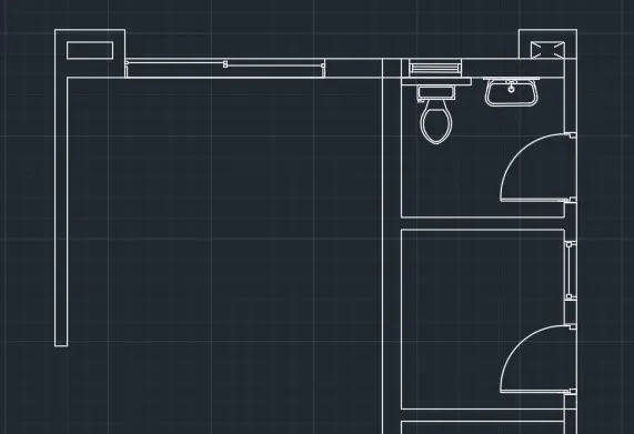
- Draw a RECTANG of 201x402 mm and EXPLODE it
- Mark all the sides using 230mm wall for top and 150 mm wall for left and right side
- Use LINE to mark the dashed line in it
Drawing of bedroom-1
- Draw a RECTANG of 3830x4500 mm and EXPLODE it
- Use OFFSET to mark the wall size of 230 mm at the top and 150 mm on the left side
- Leave an opening for the bedroom of 1350 mm on 150 mm wall
- Draw a box on top of Bedroom-1 of the size of 201x550 mm
- For W1 of 2430 mm, use OFFSET and LINE command
Drawing of toilet-1
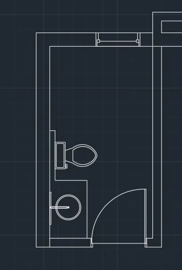
- Draw a RECTANG of 1750x3000 mm and EXPLODE it
- Mark the top and left wall as 230 mm thick using OFFSET and 150 mm bottom line
- COPY the items from the previous toilet and these here with ROTATE command
- Use LINE to mark rectangle for washbasin
- Use CIRCLE, LINE, and FILLET for drawing bash basin with mirror on the wall
- For D3, Mark the opening of 950 mm at 700 mm from the left wall and 100 mm from the right wall
- Use RECTANG, ARC, and LINE for marking door D3
- For V1, Mark opening of 750 mm at 215 mm distance from the right wall
- Use LINE and RECTANG command to mark V1
Drawing of Family room
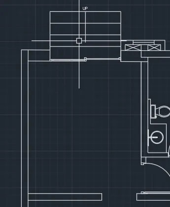
- Draw a RECTANG of 3880x4350 mm from 380mm thick top wall and EXPLODE it
- Draw wall of 380 mm at the top, 230 mm at left end, and 150 mm at bottom
- For opening at bottom of the room, draw an opening of 1200 mm at 2530 mm distance away from the left wall
- COPY the door D2 and paster it
- For SD3, make an opening of 2430 at 725 mm distance away from the left end
- Use TRIM to remove unnecessary objects
- Further, use LINE and RECTANG to draw lines in SD3
- Use LINE to draw steps to family rooms
- Use OFFSET and LINE to draw top left AP of 1515x200 mm
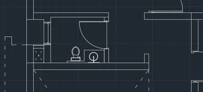
Drawing of the powder room, cupboard space, and V1
- For the Cupboard, make a dashed opening of 1170 mm using the LINE command
- For Door D3, make an OFFSET of 50 mm from the top and then COPY D3 and paste it
- Make the wall beyond the door using LINE and OFFSET command
- Make an OFFSET at 1800 mm and draw a wall of 230 mm thick
- For V1, Make an opening of 860 mm at 230 mm distance and TRIM excess objects
Placing of texts
- Use the MTEXT command to type various types of texts of varying height
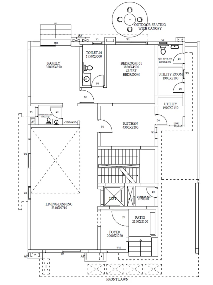
- Also name all the doors, windows, and rooms with the size of each room
Results: result is shown in monochrome style
DRAWING OF KITCHEN LAYOUT
Aim:
Drawing of kitchen layout with proper dimensions
Procedure:
Setting up Workspace
- Open AutoCAD and press ctrl+N with the metric system to open a new drawing
- Type UNIT and set units as a decimal with inputs in millimeters
- Type LAYER command to open layer box and create various layers for drawing. Requisite needed layers will be created during the course of the drawing
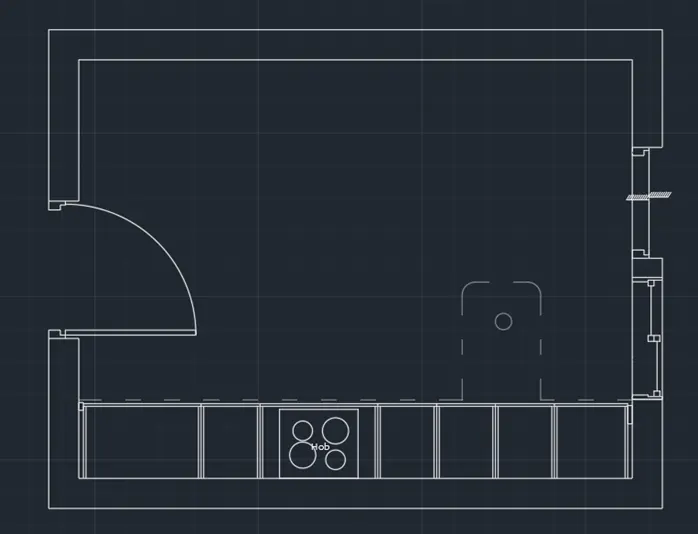
Below counter plan drawing
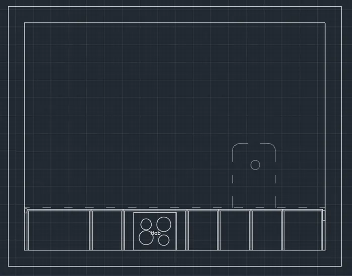
Drawing kitchen boundary
- Draw a RECTANG of 4300x3200 mm and EXPLODE it
- Draw all walls of 230 mm thickness using OFFSET
- Use FILLET for joining ends
Drawing of bottom objects with the dashed line
- OFFSET by 600 mm for bottom dashed line with 50 transparency
- Draw a RECTANG at the left end of the bottom dashed line
- Use LINE, OFFSET, TRIM, and EXTEND to draw all the rectangular shapes below the dashed line as per the dimension given
- Draw a RECTANG and CIRCLE in it for drawing hob
- Draw the snack counter at 2930 mm from the left wall. The size of the snack counter is 600x900 with a chamfer in the corners
- Use CIRCLE to draw a circle on the snack counter
Drawing of D2 and 2 windows a backside
- For D2, draw the door of 1050 mm width at 1070 mm distance of bottom-line using OFFSET
- Use LINE, ARC, and RECTANG command to draw door D2
- For Window, Draw an opening of 910 mm at 604 mm distance using the OFFSET command
- Use LINE and RCETANG to draw the window as shown
- For another window above this, mark the opening of 848 mm at 146 mm above the drawn window
- Use LINE and RCETANG to draw the window as shown in the drawing
Drawing of Fridge
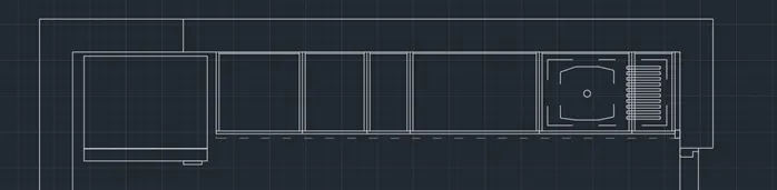
- Carve out the 1000 mm stretch for the fridge using OFFSET
- Draw a RECTANG of 858x644 mm in it
- Draw the front parts of the fridge using COPY and RECTANG command
Drawing of micro-oven
- Make an OFFSET of 1000 mm from the left wall and a further 20 mm for the oven boundary
- Make a RECTANG of 560x540 for the oven and EXPLODE it
- All sides of the oven have a thickness of 20 mm thickness except the top which is 10 mm thick
- Draw an OFFSET of 600 mm from the boundary with dashed LINETYPE
Drawing of A1 to A10
- Use the combination of LINE, RECTANG, TRIM, FILLET, and OFFSET to draw all the shapes as given in the diagram
- For drawing washbasin in A9 and A10, first, use RECTANG with dashed line type and use RECTANG with FILLET with radius option for other shapes within the dishwasher
- Mark the solid walls at 1000mm for the top wall and 1400 mm for the bottom wall as shown
Inserting texts and dimensions
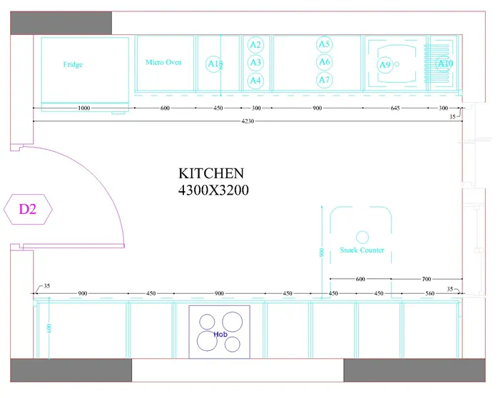
- Use the MTEXT command to place multiple texts in the kitchen
- Use DIMLIN and DIMCONT to draw all the dimensions of the kitchen as shown
- Use the HATCH command to fill the hatch in walls as shown
Results:
Above counter plan drawing
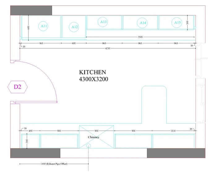
- COPY all the walls, gate, and windows from below counter the plan for drawing as both are similar
- Drawing of bottom appliances like chimney and others for using LINE, OFFSET, TRIM, EXTEND and RECTANG
- For drawing of A11 to A15, again use LINE, RECTANG, OFFSET, TRIM, EXTEND to draw as per the drawing
- Use DIMLIN and DIMCONT for dimension measurement and MTEXT and CIRCLE for text marking as shown
Result:
For Above the counter plan
DRAWING OF COLUMN DETAILS
Aim:
Drawing of column details with reinforcements as shown
Procedure:
Setting up Workspace
- Open AutoCAD and press ctrl+N with the CGS system to open a new drawing
- Type UNIT and set units as architectural with inputs in inches
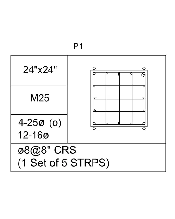
Drawing of P1
- Draw the RECTANG of 24”x24” for column size
- Place the 4-25ø and 12-16ø bars as shown in P1 at the designated place
- Use CIRCLE to drawbars of 25mm and 16 mm and place them at designated place using COPY with Array, MIRROR, and ROTATE command
- Again, use CIRCLE to draw the circle to show the location of 25mm dia bars
- Use LINE to draw the stirrups of 8ø bars as shown in P1
- Draw a boundary around it using the RECTANG command
- Use OFFSET and LINE commands to make boxes for inserting different texts
- MTEXT for inserting texts as shown in the drawing
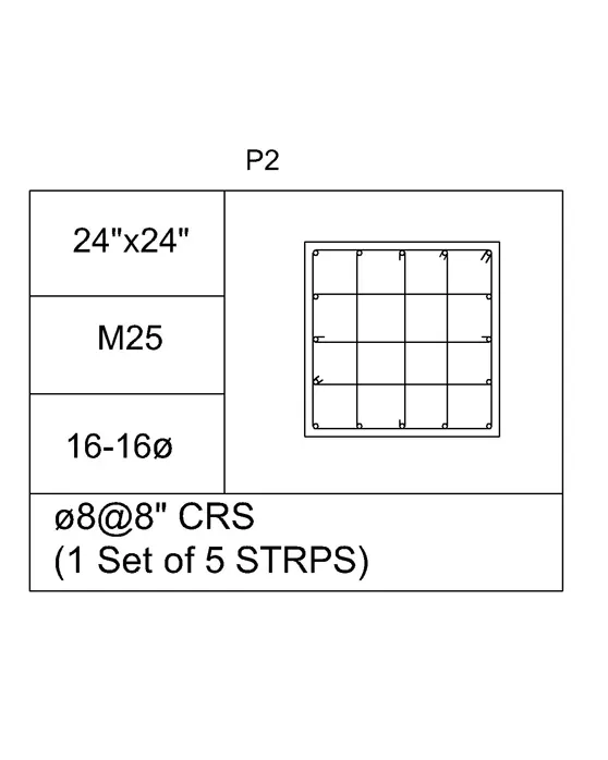
Drawing of P2
- Draw the RECTANG of 24”x24” for column size
- Place the 16-16ø bars as shown in P2 at the designated place
- Use CIRCLE to the drawbar of 16 mm and place them at designated place using COPY with Array, MIRROR and ROTATE command
- Use LINE to draw the stirrups of 8ø bars as shown in P2
- Draw a boundary around it using the RECTANG command
- Use OFFSET and LINE commands to make boxes for inserting different texts
- MTEXT for inserting texts as shown in the drawing
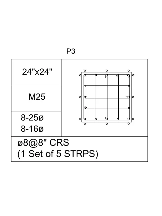
Drawing of P3
- Draw the RECTANG of 24”x24” for column size
- Place the 8-25ø and 8-20ø bars as shown in P3 at the designated place
- Use CIRCLE to drawbars of 25mm and 20 mm and place them at designated place using COPY with Array, MIRROR and ROTATE command
- Again, use CIRCLE to draw the circle to show the location of 25mm dia bars
- Use LINE to draw the stirrups of 8ø bars as shown in P1
- Draw a boundary around it using the RECTANG command
- Use OFFSET and LINE commands to make boxes for inserting different texts
- MTEXT for inserting texts as shown in the drawing
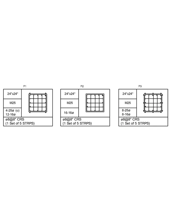
Results:
All the size bars are shown as depicted in question
8mm – 0.31 inches
25mm – 1 inch
16mm – 0.62 inches
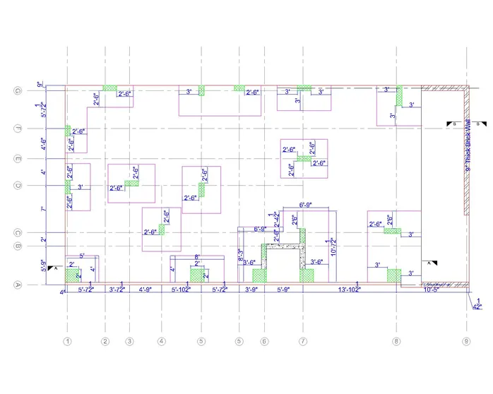
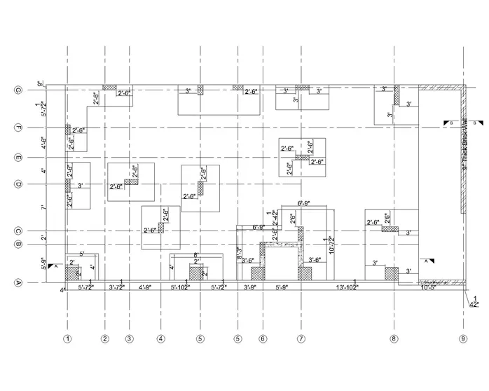
DRAWING OF RAFT LAYOUT
Aim:
Drawing of raft layout as shown in figure
Procedure:
Setting up Workspace
- Open AutoCAD and press ctrl+N with the CGS system to open a new drawing
- Type UNIT and set units as architectural with inputs in inches
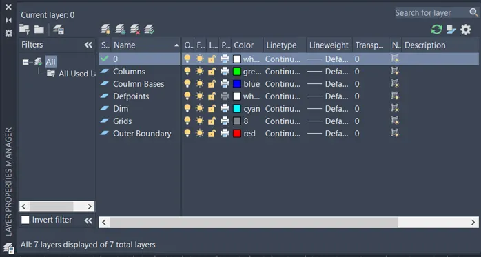
- Open LAYER and create various layers as required in drawing
Drawing of outer boundary and coordinate directions
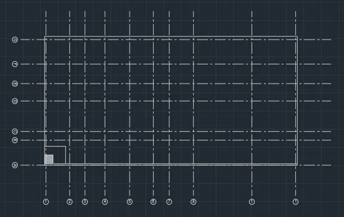
- Draw a RECTANG of 60’x29’7.5” for the outer boundary and EXPLODE it
- Marking the wall thickness along the numbered direction by 4” using OFFSET
- Mark the first section along number 1 using a dashed line with OFFSET of 4”
- Drawing of column A1 using RECTANG of 5’x4’ for column base and 2’x2’ for column size
- Use HATCH for marking column size in column base
- Marking of number direction such as 2,3,4,5,6,7,8 and 9 at shown distance
- Marking of alphabetical direction such as A, B, C, D, E, F, and G at shown distance
- Change of the DIMSTYLE of all the marking lines to center type in dashed format
- Use CIRCLE and MTECT to place the numbers
Drawing of A5, A6, A7, A8, B6, C7, and A9
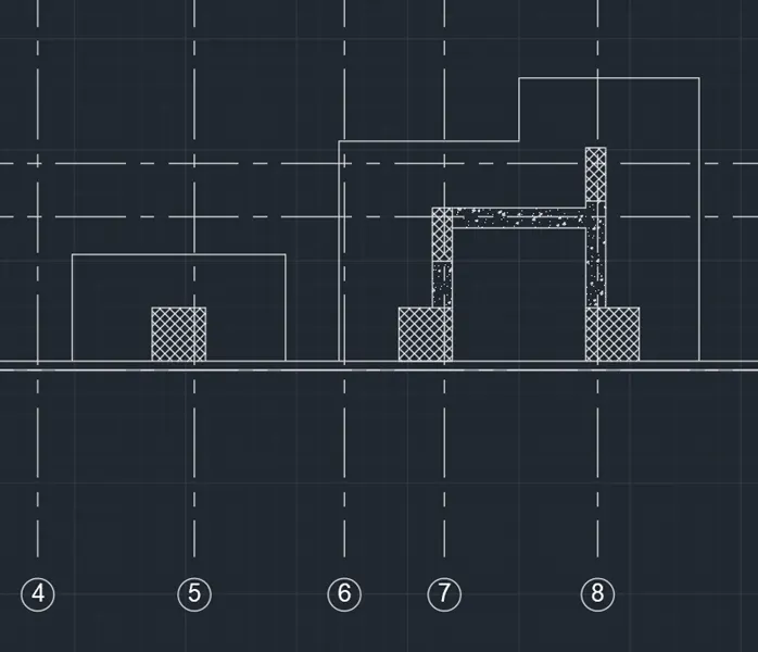
- For A5, OFFSET first drawing by 10’7.5” and then draw a RECTANG of 8’x4’ for column base
- Draw a column of 2’x2’ and HATCH it
- For A6, A7, B6, and C7, draw a RECTANG at a distance of 2’0.0833” from A5 and draw a polygon with sides 8’3”, 6’9”, 2’4.5”, 6’9”, and 10’7.5”
- OFFSET a distance 2’3” and draw a column 2’x2’ (A6)
- Draw OFFSET at 5’ and draw a column of 2’x2’ (A7)
- For B6, at 1’9” distance draw a column of 9”x2’
- Join the B6 and A6 using the wall of 9” thickness
- For A7, Draw a column of 2’x2’ at a 5’ distance
- For B7, Draw a column of 9”x2’ above 4’0.0833” of A7
- Connect the B7 and A7 using concrete beams
Drawing of A8 and C8
- First, draw a RECTANG of 8’x10’8” at 5’9” and EXPLODE it
- For A8, draw a column of 2’x2’ at 3’ from the left end of rectangular
- For C8, draw a column of 2’6”x9” at a 5’4” distance
Drawing of 9” thick bottom wall
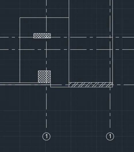
- Draw a RECTANG of 7’x9” at the bottom side from the right side of the plan as shown in the plan
- Use HATCH to fill it
Drawing of C5
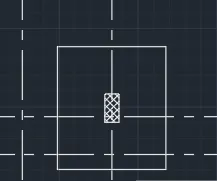
- Draw the C5 column base of 5’9”x6’6” as RECTANG starting from 11’6” from left and 4’7.5” from the bottom line and EXPLODE it
- Draw a column of 9”x18” using RECTANG and HATCH it
Drawing of D1, D3, and D5
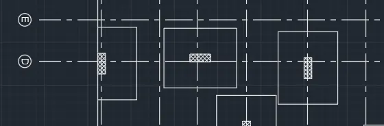
- Draw the D1 column base of 3’9”x7’ as RECTANG starting from 0 from left and 11’0.5” from the bottom line and EXPLODE it
- Draw a column of 9”x18” using RECTANG and HATCH it
- Draw the D3 column base of 7’x5’9” as RECTANG starting from 6’4.5” from left and 12’0.045” from the bottom line and EXPLODE it
- Draw a column of 18”x9” using RECTANG and HATCH it
- Draw the D5 column base of 5’9”x7’ as RECTANG starting from 17’4.5” from left and 10’7.5” from the bottom line and EXPLODE it
- Draw a column of 18”x9” using RECTANG and HATCH it
Drawing of F1, G2, G5, G7, E7, and G8
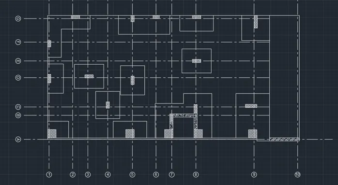
- For all the rest columns F1, G2, G5, G7, E7, and G8 follow the same procedure of finding column base length from starting point of the grid and draw inside the column with HATCH inside it
Drawing of 9” thick top and right-side wall
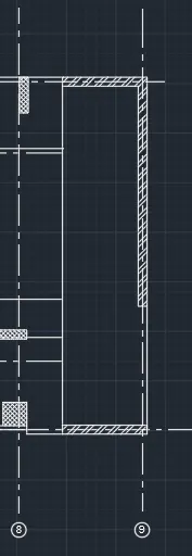
- First, draw the center LINE of 9” thick wall on the top sidewall with dashed line type
- Use OFFSET to draw a 9” thick wall with the grid in the middle of the wall on both sides
- HATCH the wall
Drawing of dimensions
- Use DIMLIN and DIMCONT to draw all the given dimensions as a separate layer
- Use MTEXT to type all the texts in the drawing
- Marking of Cut Off sections A and B
- Assign various parts to respective layers as shown in the final result
Results:
Shown in both monochrome and color format
Conclusion:
In this extensively elaborated exercise, almost all the majorly used commands like – LINE, RECTANG, OFFSET, FILLET, EXTEND, TRIM, CIRCLE, MIRROR, ROTATE, ARRAY, COPY, MOVE, ARC, PLINE, CIRCLE, TEXT, MTEXT, DIMLIN, DIMCONT, DIMBREAK, QLEADER, TABLE, LAYER, DIMSTYLE, LINETYPE, LINEWEIGHT, EXPLODE, PDFIMPORT, HATCH to name a few. Apart from these other properties like the thickness of lines were also extensively used.
This extensive use of commands with practical drawing gives a very good exercise. This knowledge gives the edge in the quick and timely drawing of objects in AutoCAD.