Creating a Wardrobe detailed drawing, Floor Plan, Kitchen Layout and Column Detail using AutoCad
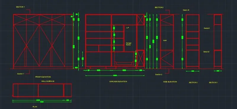
1) Aim :- To draw the elevation and details of a wardrobe as shown in the question.
Procedure :-
- download the pdf file of the elevation to be drawn. open a new cad file and make th eunits into mm .
- enter option xref - attach pdf - select the downloaded pdf file - press enter
- measure a dimension . we observe that the file downloaded is in a different scale
- to scale the drawing, enter scale option - select the object- select base point- select referance-the first length to be entered is the reference length ( the length that we measured in the file )- the second length to be entered is the new length( the actual length that we require.)
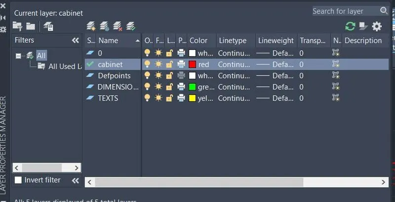
- make a layer and name it 'cabinet' ,to draw the elevation an dother details of the drawing.give it a colour red.
- now draw over the drawing using line option and marking the ortho mode on.
- make another layer called 'dimensions' and give it a colour green, and then dimension our drawing using dimension option.use dimcontinue to get all the dimensions in a particular row or coloumn continously.
- make a third layer and name it ' texts', and using text option write down the required texts. Make this layer in another colour say yellow.
- after completion of the drawing copy the drawing that we made and paste it separately
- the resulting drawing is as given below.
2) Aim:- To draw the floor plan as shown in the Figure.
Procedure:-
- download the pdf file of the plan to be drawn. open a new cad file and make the units into mm .
- enter option xref - attach pdf - select the downloaded pdf file - press enter
- measure a dimension . we observe that the file downloaded is in a different scale
- to scale the drawing, enter scale option - select the object- select base point- select referance-the first length to be entered is the reference length ( the length that we measured in the file )- the second length to be entered is the new length( the actual length that we require.)
- make a layer and name it 'floor plan' ,to draw the elevation an dother details of the drawing.give it a colour red.
- now draw over the drawing using line option and marking the ortho mode on. use dotted lines wherever required.
- make another layer called 'dimensions' and give it a colour blue, and then dimension our drawing using dimension option.use dimcontinue to get all the dimensions in a particular row or coloumn continously.
- make a third layer called 'windows', with a pyrple colour and then draw the windows. similarly with doors also .
- make another layer and name it ' texts', and using text option write down the required texts. Make this layer in another colour say yellow.
- after completion of the drawing copy the drawing that we made and paste it separately
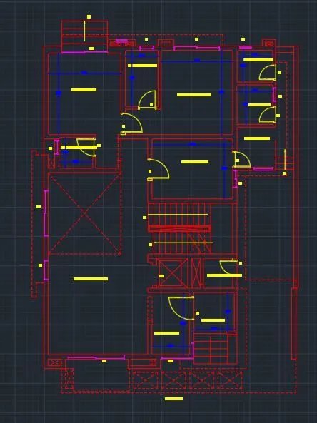
- the resulting drawing is as given below
3) Aim :- To create a kitchen layout as given in the question
Procedure:-
- download the pdf file of the plan to be drawn. open a new cad file and make the units into mm .
- enter option xref - attach pdf - select the downloaded pdf file - press enter
- measure a dimension . we observe that the file downloaded is in a different scale
- to scale the drawing, enter scale option - select the object- select base point- select referance-the first length to be entered is the reference length ( the length that we measured in the file )- the second length to be entered is the new length( the actual length that we require.)
- make a layer and name it 'kitchen plan' ,to draw the elevation an dother details of the drawing.give it a colour yellow.
- now draw over the drawing using line option and marking the ortho mode on. rectangle option is also used for drawing.
- make another layer called 'text/dim' and give it a colour white, and then dimension our drawing using dimension option.use dimcontinue to get all the dimensions in a particular row or coloumn continously. write the required texts using text option.
- make a third layer called 'D/W', with a purple colour and then draw the doors and windows. similarly with doors also .
- make another layer and name it ' texts', and using text option write down the required texts.
- after completion of the drawing copy the drawing that we made and paste it separately
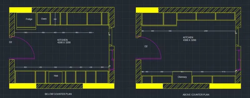
- the resulting drawing is as given below
4) Aim :-
Procedure :-
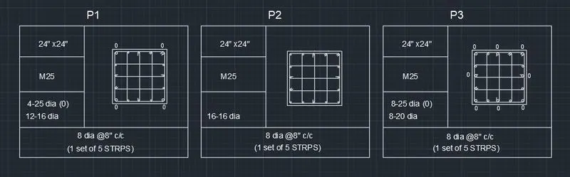
- select a new aytocad drawing with unit as inches.
- draw a rectangle using line option with dimension 24" x 24". offset 1" inside .offset the lines in vertical and horizontal direction so as to make a grid.
- using fillet option , smoothen the edges with radius appropriate to the diameter of the bar inside it.
- using extend option complete the drawing . niw we have the column section.
- make 3 copies of the column section
- using circle option make circles of diameter 1, 0.8 and 0.62 which represent reinforcement bars of diameter 25mm, 20mm and 16mm respectivley
- cpy and paste these reinforcements on all 3 column sections as per the drawing. make hooks using line option.
- now to make the table, draw a rectangle using line option an dusung offset option make 4 rows and 2 columns. edit it using trim otion and then make 3 copies of the same .
- using text option write down the required texts .
- the resulting drawing is as given below.
5) AIM :- To create a raft layout as given in the question
Procedure :-
- download the pdf file of the plan to be drawn. open a new cad file and make the units into inches .
- enter option xref - attach pdf - select the downloaded pdf file - press enter
- measure a dimension . we observe that the file downloaded is in a different scale
- to scale the drawing, enter scale option - select the object- select base point- select referance-the first length to be entered is the reference length ( the length that we measured in the file )- the second length to be entered is the new length( the actual length that we require.)
- select construction line option and with the line option as hidden 2 , draw construction lines over the imported pdfs.
- after that ,draw over the drawing using line option and marking the ortho mode on.
- draw the boundaries, walls , rafts (cyan colour) in a similar using line option and rectangle option.
- now draw a rectangle of size 24" x 24" and colour yellow. select hatch option and give it a cross shaped hatch and white colour. this is the column of size 24" x24". now make this into a block and using block option and name it C1.
- similarly make C2,C3,C4 of sizes 9” x 24”, 9” x 18”, and 9’ x 24” respectively and place them wherever required according to the drawing.
- next dimension the drawing using dimension option. use dimstyle to select alternate units and make the units visible in both inches and feet. use dimcontinue to get all the dimensions in a particular row or coloumn continously.
- using text option ,write the required texts .
- after completion of the drawing copy the drawing that we made and paste it separately
- the resulting drawing is as given below
