Creating a Wardrobe detailed drawing, Floor Plan, Kitchen Layout and Column Detail using AutoCad
1.
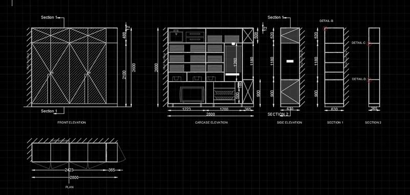
AIM: To Draw the elevation and details of a wardrobe as shown in the Figure.
PROCEDURE:
1. First and for most set the unit to decimal and mm
2. Then setup the dimension setting
3. Sketch the plan with the given dimension with the help of line and rectangular command
4. make sure you hatch the wall portion
5. Now take the elevation of the plan
6. Sketch the elevation with the given height in the figure
7. and Hatch the required portion
8. Now take the side projection of the elevation to draw the Carcase elevation
9. Sketch the elevation and make sure to draw the object inside it and make the transparent
10. With the help of line command take the side projection for sections 1-1, section 2-2, and side elevation
11. With the help of the Dimlinear command determine the dimension of the geometry
12. with the help of the Text command determine the text required as per the given figure
RESULT:
2.
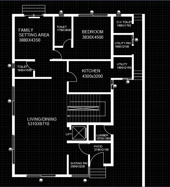
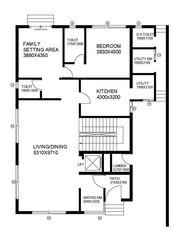
AIM: To Draw the floor plan as shown in the Figure.
PROCEDURE: (As per the question the furniture and the hatching are not done in the plan except for wall hatching)
1. Change the unit to Engineering and inch
2. Determine the number of layers you need to create the layout
3. Eg: Layer 1 = Internal and External Walls
Layer 2 = Staircase
Layer 3 = Hatching
Layer 4 = Text & Dimension
4. Starting with External Wall from the Bottom left corner using the Xline command Horizontal and vertical
5. Complete the External wall with 230mm Thickness and head towards the internal wall with 150mm By using line, offset, Trim, Fillet commands, etc
6. Determine the number of steps required for the staircase with the help of the Riser and tread Dimension. Draw the steps with the help of a line and offset commands
7. Hatch the wall with the help of the hatch command
8. Providing the door dimension For the front 1200mm and rear sliding door 3000mm
9. Windows of width 3000mm and ventilators 700mm width
10. With the help of the Arc command draw the arc for the door
11. Lastly Now with the help of the dimension and text command display the length and dimension of each room
RESULT:
3.
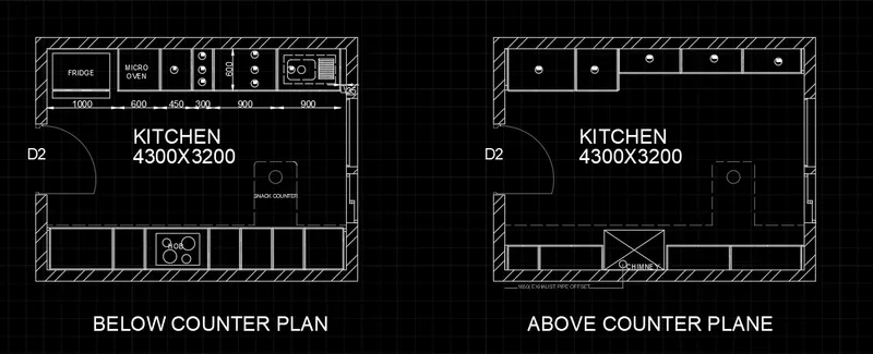
AIM: To Create the Kitchen layout for the Below counter plane and Above counter plane
PROCEDURE:
1. Change the Unit to decimal and mm
2. Considered the thickness of the wall 230mm
3. Draw the wall with the help of line, Trim, and Offset command
3. Hatch the wall portion As per the given drawing
4. providing Doors, windows, and ventilators as per the given dimension in the figure
5. Determine the dimension of the rooms with help of dimension and text command
RESULT:
4.
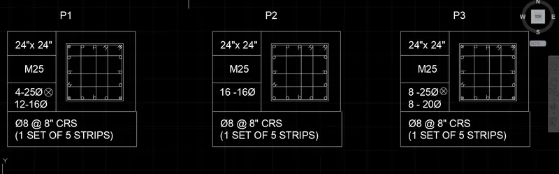
AIM: To Sketch the column details as shown in Figure.
PROCEDURE:
1. Change the unit to engineering and inches.
2. Draw the tabular column with line and rectangular command
3. Use the Text command to create text in a tabular column
4. Use font name: Arial; Height: 8”, Justify: Left
5. Create the reinforcement details using line, rectangular, and circle command
6. Hatch the required geometry as per the required reinforcement details
RESULT:
5.
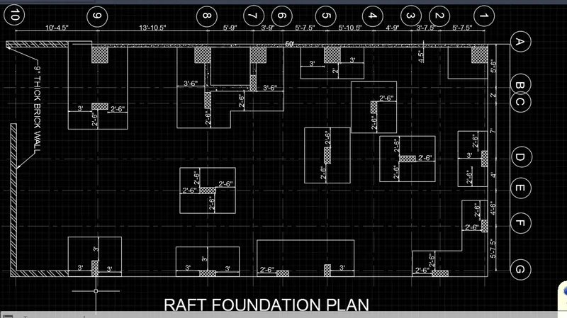
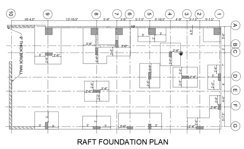
AIM: To Draw the Raft Layout as shown in the Figure
PROCEDURE :
1. Primarily change the unit to engineering and inches
2. Then mark all the grid points as per the given specification in the drawing
3. Now create a concrete wall and a masonry wall of 9" thick
4. Sketch the column with the help of the rectangle command for different sizes eg. 24"x24", 9"x 24", and 9"x18". sketch it as ans single entity
5. Now with the help of copy command+ multiple places the column as per the grid positioning provide in the drawing
6. Number and name the grid point A, B, C, E, G, & 1,2,3,4,5,6,7,8,9,10.
7. Sketch the footing for the column as per the given size
8. Hatch the required portion with the hatch command
9. With the help of a text command determine the text need
10. And with help of dimliner+ continue command dimension is been provided
RESULT: