Creating a Wardrobe detailed drawing, Floor Plan, Kitchen Layout and Column Detail using AutoCad
1.
AIM:- To Draw the elevation and details of a wardrobe.And use layers to show the different parts of the wardrobe.
PROCEDURE:-
- Draw a horizontal baseline and give offset of 2600 mm.
- now give the offset of 900mm and 1180mm respectively to form the wardrobe boxes.
- Now give vertical lines joining the horizontal lines and give them spacing that we needed to create a perfect box like shape.
- And then trim the excess lines.
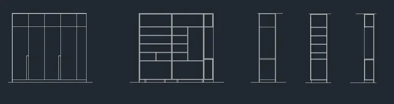
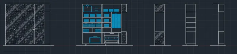
- Now draw the components like clothes and hanger and bags which isput in the wardrobe.
- The components to be drawn in the different layer and colour so it can be differenciated easily.
-----------------------------------------------------------------------------------------------------------------------------------
2.
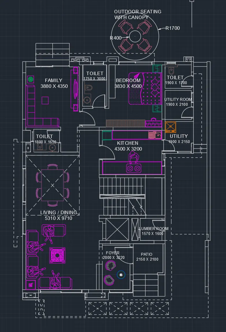
AIM:- To Import the Floor_Plan.pdf into your current drawing and start working on the project. You need to scale the imported pdf file using reference option. All dimensions are in mm.
- Walls (Exterior and Interior)
Wall Thickness: Exterior Wall- 230mm, Interior Wall: 150 mm (Wherever Required)
- Doors and Windows: Assume the size of the doors and window.
2.1 Stairs: Tread-300mm, Riser-150mm
- Insert Text wherever required
- Insert the dimensions using proper dimension techniques
PROCEDURE:-
- At first attach the pdf in the autocad by using attach tool in the insert bar.
- Now scale the pdf according to the dimensions in written in the pdf.
- Now draw line on the lines shown in the pdf to create a replica of the building plan shown in the question.
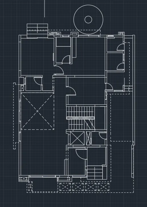
- Now for the furniture components import the blocks from another drawing or download it online.
- Give then a different layer so that they look apart from the drawing.
- Now give names and size to each and every room drawn.
-----------------------------------------------------------------------------------------------------------------------------------
3.
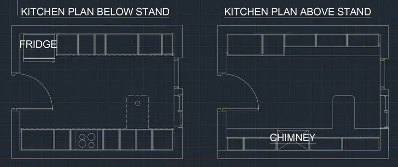
AIM:- To Create the Kitchen Layout as shown in the question with required kitchen equipments and notations.
Procedure:-
- At first attach the pdf in the autocad by using attach tool in the insert bar.
- Now scale the pdf according to the dimensions in written in the pdf.
- Now draw line on the lines shown in the pdf to create a replica of the kitchen plan shown in the question.
- Now give the notations using "DTEXT" command whereever needed.
---------------------------------------------------------------------------------------------------------------------------------
4.
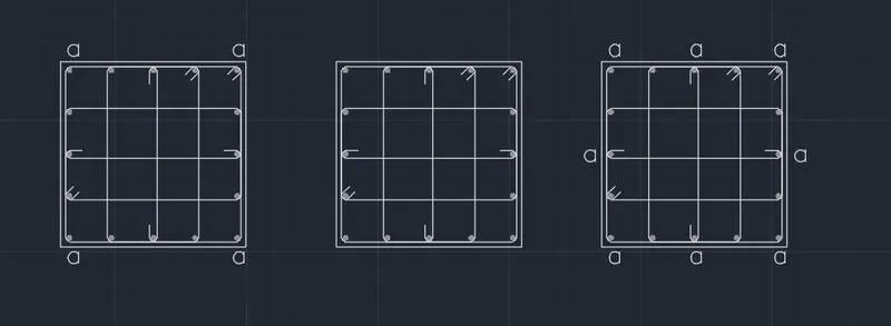
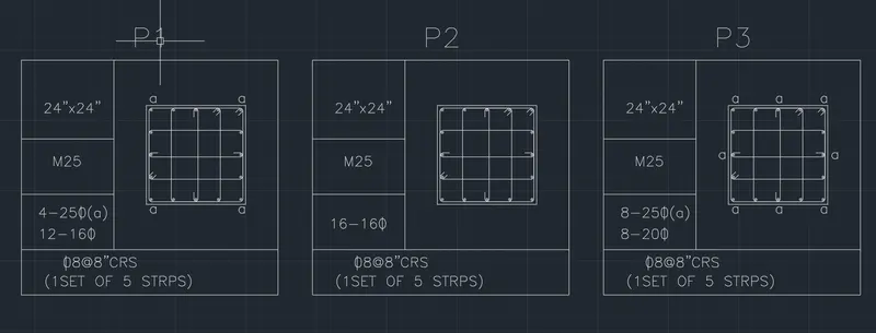
AIM:- to Sketch the column details as shown in Figure. Insert dimensions and text in the figure.
PROCEDURE:-
- For 1st type of column draw a rectangle of 24"X24" by using "REC" command.
- Now give offset of 1.5" (assuming the size of cover provided to reinforcement)to the rectangle inside the rectangle by using command "O"
- Now explode the inner rectangle by using "X" command
- Now give the fillet of the 0.5" to the inner rectangle by using command "F" and then select the fillet radius as 0.5"
- Now draw a circle of 0.5" on both the corners of the inner rectangle in such a way that the boundary of the circle and fillet arc overlaps each other.
- Now select both the circle then enter the command copy "CO" and then select the side quardent point of the circle and then select "array" and then enter the no. of copies as "5" and then select "Fit" and then select upper end of the fillet arc located on the bottom of the rectangle.
- Now add hatch to the circles by using the "Hatch" command and then selecting the type of hatch as solid.
- Now provide the horizontal lines connecting the circles at the quardent point where need.
- Now add lines at 45 degree angle to show the bended strips where needed by using start point as the tangent of the circle.
- Now draw a rectangle with the help of "LINE" command of size of 7'X6'.
- Now give the horizontal line the offset of the 1' & 4' respectively to create the three rows.
- Now Give the offset of 2' to the vertical line .
- Now trim horizontal lines in the second columns to create a table for the Scheduling for the column
- Now enter the required data in the boxes using Single line text by "DTEXT" command.
- And move the drawn columns in the respected boxes.
-------------------------------------------------------------------------------------------------------------------------------------
5.
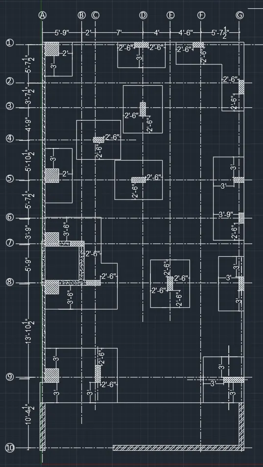
AIM:- To Draw the Raft Layout as shown in the Figure. Assume the column size as per your knowledge. You can take the sizes as: 24”x24”, 9” x 24”, 9” x 18”, and 9’ x 24”. You can import the raft_foundation.pdf to ensure the missing dimensions.
PROCEDURE:-
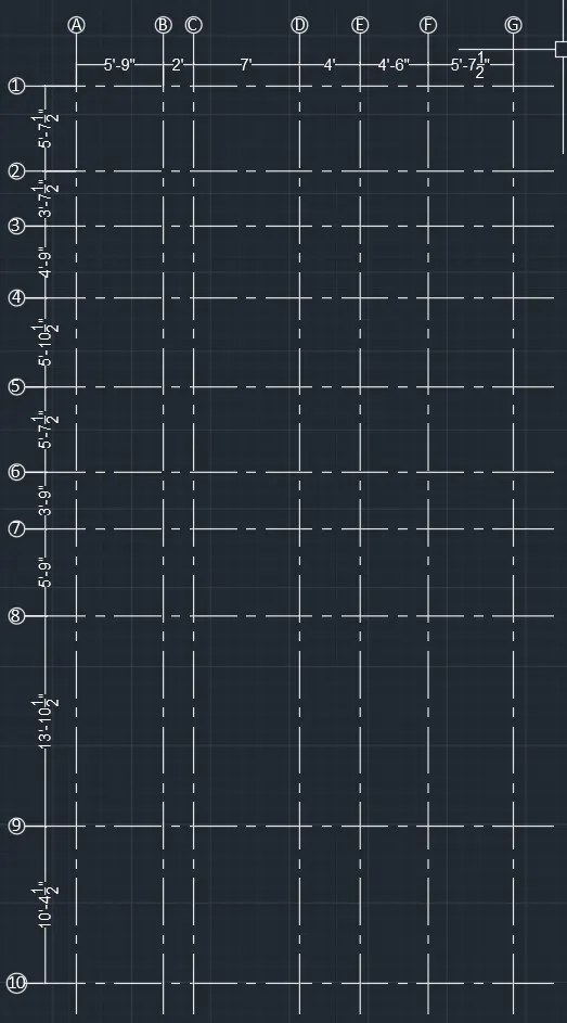
- Draw a grid by following steps.
- Draw a verticle line with the linetype "CENTRE"
- Now give the vertical line following offsets respectively, (5'9", 2', 7', 4', 4'6", 5'7`1/2`")
- Draw a horizontal line on the top with the linetype "CENTRE"
- Now give the horizontal line following offsets respectively, ( 5'7`1/2`", 3'7`1/2`", 4'9", 5'10`1/2`", 5'7`1/2`", 3'9", 5'9", 13'10`1/2`", 10'4`1/2`")
- Now draw a circle at the top of the vertical lines and on the starting points of the horizontal lines.
- Now put the text in the circle using "DTEXT" to give the numbering to the grid lines.
- Now draw the columns by using the grid points of the desired size.
- Now draw the rectangles around the column to show the size of the excavation to be done for the foundation.
- Now put the dimensions around the clomns and excavation area to specify the size of the drawings.
- Now apply hatch to the columns to differentiate it from the other drawing or to get it highlighted.