Creating a Wardrobe detailed drawing, Floor Plan, Kitchen Layout and Column Detail using AutoCad
Challenge 6: Creating a wardrobe detailed drawing, residence plan, kitchen layout and columns details using AutoCAD.
- Creating Wardrobe Detailed drawing.
Aim – To draw a wardrobe detailed plan ,front elevation, side elevation using AutoCAD software.
Procedure:
- First create a new Autocad file with metric units
- Type the command units and set it to decimal units and set it millimetres.
- Type the command Dimstyle and in the primary unit set the units to decimal and precision to 0.
- Set the limits by using LIMITS command and specify the ends points.
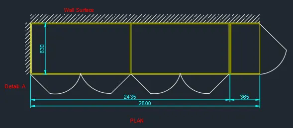
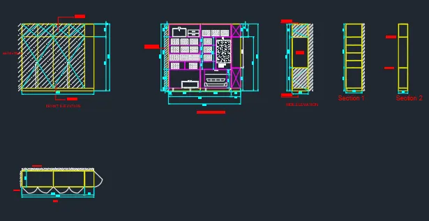
Creating plan
- Type a rectangle command and give the dimensions as 2800 mm as length and 630 mm as width.
- Now give the offset of 12 mm offset using offset command except right vertical line of rectangle
- Now from this vertical line give the offset of 365 in –x direction and again an offset of 1217.5 mm in same direction.
- Now from these two vertical line again give the offset of 12mm
- Now from the corner and middle points create a diagonal line using line command and keeping ortho mode off and then use the “start end direction “ option from Arc for making door.
- Type the hatch command for doing the hatching from corners wall surface.
- Give the dimensions and type the text using single line text by keeping height 120 and angle as 0.
- Plan is created.
Creating front elevation
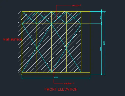
- Type a rectangle command and give the dimensions as 2800 mm as length and 2600 mm as width.
- Now give the offset of 12 mm offset using offset command except right vertical line of rectangle
- Now from this vertical line give the offset of 365 in –x direction
- Now from the below plan, from the point of gates and the middle line draw the vertical x lines.
- Trim the required lines using TRIM COMMAND.
- Required lines in the rectangle are created.
- Now for making gate potion, from the middle of the lines create a desired line in –x direction and then join it vertically downward keeping the orthomode on.
- Create cross line which indicates open space by using line command by selecting corners and making line diagonally keeping ortho off.
- Front elevation is created.
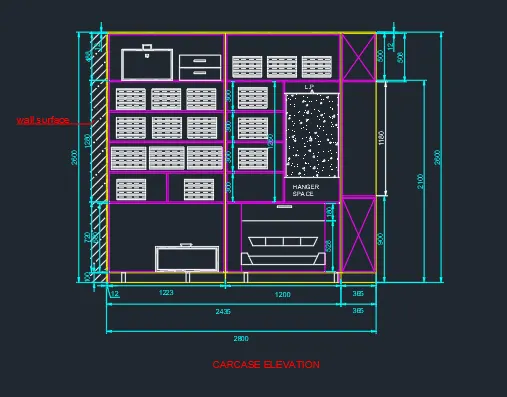
Creating Carcase elevation.
- Type a rectangle command and give the dimensions as 2800 mm as length and 2600 mm as width.
- Now give the offset of 12 mm offset using offset command except right vertical line and lower line of rectangle
- Now from this vertical line give the offset of 365 in –x direction
- Give the offset of 1200mm in the same direction.
- Now from the lower line of rectangle give the offset of 100mm in +y direction
- Now give the 0ffset of 8mm for creating inner boundary
- From the main boundary line give the offset of 488 mm in –y direction.
- Give the offset of 8mm in same direction
- Now give the offset of 300mm in Same direction.
- Again give the offset of 300 mm in –y direction
- Now give the offset of 300mm in Same direction
- Continue two more times for getting rectangles inner shelves.
- From the boundary line at 365mm distance, give the offset of 568 mm in –x direction and then give the 8mm offset for inner boundary.
- Trim the unwanted lines using trim command.
- Now for making suitcase and clothes portion use the rectangle command
- Make rectangle of 295 length and 212 width for making clothes
- Increase or decrease the size using scale command to fit the rectangle cloth portion.
- Make the suitcase by using rectangle command and giving the desired length
- Do the hatching as required using hatching command.
- Make a close portion for hatching command to do the hatching
- Mark the dimensions using dim linear
- Use the TEXT command and click on single line text for marking.
- Carcase elevation is created.
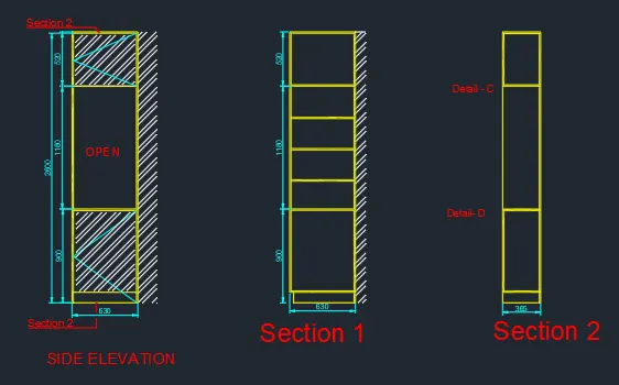
Creating side elevation.
- Type a rectangle command and give the dimensions as 630mm as length and 2600 mm as width.
- Now give the offset of 12 mm offset using offset command in whole rectangle except lower horizontal line.
- Now from the lower line of rectangle give the offset of 100mm in +y direction
- Now from the lower line of rectangle again give the offset of 900mm in +y direction
- Now give the offset of 8mm in same direction
- Again give the offset of 1180mm in same direction.
- Make a diagonal line using line command keeping ortho off.
- Type the command HATCH and do the hatching by making a close boundary with rectangle command and then erasing rectangle.
- Use TEXT command and click on single line text.
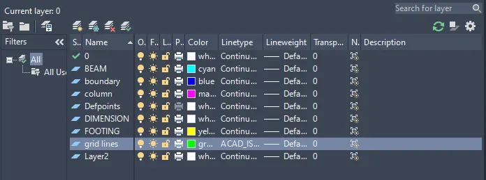
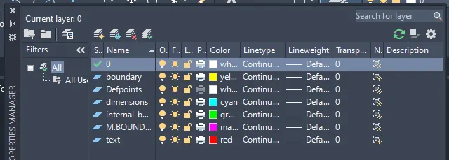
- Use the layer properties for assigning different colour to boundaries.
- Side elevation created.
- Now creating section 1
- Type a rectangle command and give the dimensions as 630mm as length and 2600 mm as width.
- Now give the offset of 12 mm offset using offset command in whole rectangle except lower horizontal line.
- Now from the lower line of rectangle give the offset of 100mm in +y direction
- Trim the required line from left side and at 20mm distance make the required small vertical line using LINE command.
- Now from the lower line of rectangle again give the offset of 900mm in +y direction
- Now give the offset of 8mm in same direction
- Again give the offset of 1180mm in same direction.
- Now divide 1180 mm length into 4 rectangle blocks of equal dimensions and also give 8mm wall boundary thickness.
- Type the command HATCH and do the hatching by making a close boundary with rectangle command and then erasing rectangle.
- Use TEXT command and click on single line text.
- Section 1 created
- Creating section 2
- Type a rectangle command and give the dimensions as 365 mm as length and 2600 mm as width.
- Now give the offset of 12 mm offset using offset command in whole rectangle except lower horizontal line.
- Now from the lower line of rectangle give the offset of 100mm in +y direction
- Now from the lower line of rectangle again give the offset of 900mm in +y direction
- Now give the offset of 8mm in same direction
- Again give the offset of 1180mm in same direction
- Now give the offset of 8mm in same direction
- Type the command HATCH and do the hatching by making a close boundary with rectangle command and then erasing rectangle.
- Use TEXT command and click on single line text.
CABINET:
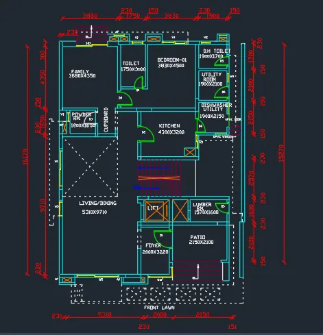
- Creating floor plan drawing.
Aim – To draw a floor plan using AutoCad software.
Procedure:
- First create a new Autocad file with metric units
- Type the command units and set it to decimal units and set it millimetres.
- Type the command Dimstyle and in the primary unit set the units to decimal and precision to 0.
- Set the limits by using LIMITS command and specify the ends points.
- Type the X LINE command and make a horizontal and vertical line
- Now trim the left side horizontal line using TRIM command
- Making family room
- Assuming the corner as the upper left corner of plan
- Give the offset of 230 mm in +x direction from vertical line.
- Again give the offset of 3880mm from the last point in the same direction
- Give the offset of 230mm in the same direction from the last point
- Now from the upper horizontal line give the offset of 300 mm in –y direction.
- Trim the required line from the right side.
- Now from the last point again give the offset of 4350mm in the same direction
- Give the offset of 150 mm in the same direction
- Use the TRIM command to trim the required lines
- Making toilet
- From the last vertical line give the offset of 1750 in +x direction
- Again give the offset of 150 mm in same direction.
- From the upper horizontal line give the offset of 230 mm in –y direction
- Now again give the offset of 3000mm in same direction
- Give the offset of 150 mm in same direction.
- Trim the required lines using TRIM command
- Now making bedroom 01
- From the last vertical line give the offset of 3830 mm in +x direction
- Now again give the offset of 230 mm in the same direction.
- Now from the upper horizontal line give the offset of 4500 mm in the –y direction
- Give the offset of 150 mm in same direction.
- Trim the required lines using trim command.
- Making D.H toilet
- From the last horizontal line give the offset of 1900 mm in +x direction.
- Again give the offset of 150 mm in the same direction
- From the upper horizontal line give the offset of 230mm in the –y direction
- Again give the offset 1700 in the same direction
- Give the offset of 150 mm in the same direction.
- Trim the required lines using TRIM command
- Making Utility Room
- From the bedroom side give the offset 1900 in +x direction.
- Again give the offset of 150mm in the same direction
- From the upper boundary give the offset 2100 in –y direction.
- Again give the offset of 150 mm in the same direction
- Trim off the required lines TRIM command
- Making Dishwasher Utility
- From the upper horizontal boundary give the 2150 mm in –y direction
- Again give the offset of 150 mm in the same direction
- Join the lines to the bedroom corner to get the vertical boundary.
- Now give the offset of 1900 mm in +x direction and 150 mm again in the same direction.
- Trim the required lines.
- Now from the boundary of DH toilet at 1000 mm distance make a main boundary of 230 mm thickness and length till lumber room.
- Making Kitchen
- From the left vertical boundary of dishwasher room give the offset of 230 mm –x direction
- Again give the offset of 4300 mm in the same direction.
- Again give the offset of 230 mm in the same direction.
- From the upper bedroom boundary give the offset of 3200 mm in –y direction.
- Give the offset of 150 mm in the same direction.
- Trim off the required lines using trim command
- Making powder room
- From the 230mm boundary wall give the offset of 300 mm in +x direction
- Again give the offset of 230 mm in the same direction
- Again give the offset 1800 mm in the same direction
- Give the offset of 150 mm in the same direction.
- From the upper boundary of family room give the offset of 1650 mm in –y direction
- Now give the offset of 230 mm in the same direction
- Trim the required lines using TRIM command
- Extend the last horizontal boundary to the vertical boundary of family room to get the cupboard space.
- Drawing Living/Dining
- From 230 mm main boundary wall in left side give the 5310 mm in +x direction
- Now from the boundary of powder room give the offset of 9710 mm in –y direction.
- Now again give the offset of 230 mm in –y direction.
- Trim the required lines using TRIM command
- Making foyer
- From the boundary of living room give the offset of 230 mm in +x direction for thickness
- Again give the offset of 2000 in +x direction
- Give the offset of 230 mm in the same direction
- From the lower boundary of living room extend the line to the intersection point.
- Trim off the required lines using trim command
- Now from lower horizontal line give the offset of 150 mm in +y direction
- Now give the offset of 3200 in the same direction.
- Give the offset of 100 mm in the same direction from last point
- Again give the offset of 230mm in the same direction
- Trim off the required lines using TRIM command
- Making Patio
- From the vertical boundary of foyer give the offset of 2150 in +x direction
- Give the offset of 150 mm in the same direction.
- Extend the upper horizontal boundary of foyer room to get the same boundary in line of patio room
- From this horizontal line give the offset 2100 in –y direction.
- Again give the offset of 150 mm in the same direction.
- Trim the required lines using TRIM Command.
- Making Lumber room
- From upper horizontal boundary of patio room give the offset of 1600 mm in +y direction.
- Extend the right vertical boundary of patio room to get the intersection point.
- Trim off the required lines.
- Now give the offset of 1570 mm in –x direction.
- Again give the offset of 150 mm in same direction for thickness of wall.
- Extend the vertical boundary of foyer room to get the lift space.
- Making stairs
- Type line command LINE and make a vertical line joining the boundary of kitchen and lift wall boundary.
- From centre point make 150mm line both sides to get the thickness of open space.
- Make the space with the help of line command till the boundary of kitchen
- Now give the offsets of 150 mm to get the required no. of treads.
- From the centre of the horizontal boundary of patio room make a line touching the boundary of foyer room
- Now give the 150 mm required offsets for getting stairs.
- Do the same for the rest of the stairs present in the plan.
- Making doors
- Trim the lines for getting open space.
- Use the “start end direction” option from the arc to make the curve portion
- Make the required small thickness with the help of line command
- Making open spaces
- Use the offset command by extending the boundaries.
- Use line command for joining and getting open space.
- Use the line command and keeping ortho off for getting diagonal lines.
- Making windows.
- Use the rectangle command for getting small rectangles.
- Use the line command for joining the straight lines from middle of rectangles.
- Use the offset command for getting window.
- Do the same for the rest of the window.
- Use the single line text for writing and detailing.
- Do the dimensioning as required.
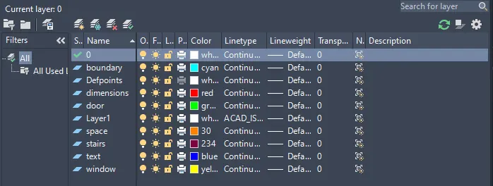
- Use the layer properties for showing all parts in different colours.
- Kitchen Layout
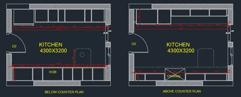
Aim – To draw the kitchen layout using AutoCad software.
Procedure:
- First create a new Autocad file with metric units
- Type the command units and set it to decimal units and set it to millimeters
- Type the command Dimstyle and in the primary unit set the units to mm and precision to 0.
- Set the limits by using LIMITS command and specify the ends points.
- Making Below Counter Plan
- Type the rectangle command REC and give the dimension, length= 4690 mm and width =3720 mm
- Give the offset of 230 mm from all the sides in the inner portion
- Trim off the required lines using TRIM command
- From the upper side give the offset of 20 mm in –y direction
- Again give the offset of 720 mm in the same direction
- From the left side give the offset of 35 mm in +x direction
- Again give the offset of 1000 mm in same direction
- Trim off the required lines and fridge is shown
- Now from the upper horizontal line give the offset of 580 mm in –y direction
- From this line give the offset of 20 mm in the +y direction
- From the last vertical line (fridge) give the offset at the distance of 50 mm in +x direction
- Now again give the offset of 20 mm in same direction
- Trim off the required lines
- From the last vertical line give the offset of 580 mm in the +x direction
- Again give the offset of 450 mm in the same direction.
- Again give the offset of 300 mm in the same direction.
- Again give the offset of 900 mm in the same direction.
- Again give the offset of 300 mm in the same direction.
- Again give the offset of 945 mm in the same direction.
- Now from the middle lines give the offset of 10 mm on both the sides and the right corner shelf line give the offset as 20 mm
- Repeat the same for the lower portion as only dimensions are different.
- Make a ISO Dash line from the layer properties
- Make the ISO line at the distance of 10 mm from the horizontal lines at both upward and downward sides
- For making the snack counter use the line command and give the vertical length as 900 mm and horizontal length as 750 mm
- Use the fillet command FILLET for getting the round corners by clicking on the radius and giving the specified radius
- Select the point and use the circle command and give the radius as 95 mm
- Use the trim command for making the door space
- Use the “start end direction” option from the arc as shown in the ribbon for getting the shape of the door
- Use the rectangle and line command for making window
- Use the hatch command and make a close boundary for doing the hatching
- Use the single line text for writing and do the dimensioning.
- Making Above Counter Plan
- Type the rectangle command REC and give the dimension, length= 4690 mm and width =3720 mm
- Give the offset of 230 mm from all the sides in the inner portion
- Trim off the required lines using TRIM command
- From the upper side give the offset of 20 mm in –y direction
- Again give the offset of 600 mm in the same direction
- Give the offset twice of 10mm in +y direction
- From the left side give the offset of 35 mm in +x direction
- Again give the offset of 965 mm in same direction
- From this line give the offset of 10 mm in both the sides
- Trim off the required lines
- Now from the upper horizontal line give the offset of 600 mm in –y direction
- From this line give the offset of 10 mm in the +y direction
- From this line give the offset of 10 mm in the +y direction
- Now from the last vertical line give the offset of 600 mm in +x direction.
- Now again give the offset of 20 mm in same direction
- Trim off the required lines
- From the upper horizontal line give the offset 320 mm in –y direction
- From this line give the offset of 20 mm in the +y direction
- From the last vertical line give the offset of 20 mm in the +x direction
- Trim off the required lines
- From the last vertical line give the offset of 865 mm in the +x direction
- Again give the offset of 865 mm in the same direction.
- Again give the offset of 865 mm in the same direction.
- Right corner shelf line give the offset as 20 mm
- Repeat the same for the lower portion as only dimensions are different.
- Make a ISO Dash line from the layer properties
- Make the ISO line at the distance of 10 mm from the horizontal lines at both upward and downward sides
- For making the snack counter use the line command and give the vertical length as 900 mm and horizontal length as 750 mm
- Use the fillet command FILLET for getting the round corners by clicking on the radius and giving the specified radius
- Use the trim command for making the door space
- Use the “start end direction” option from the arc as shown in the ribbon for getting the shape of the door
- Use the rectangle and line command for making window
4.Creating columns.
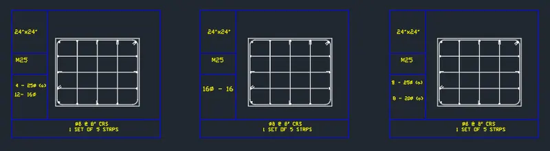
Aim – To draw columns geometry using AutoCad software.
Procedure:
- First create a new Autocad file with imperical units
- Type the command units and set it to decimal units and set it to inches.
- Type the command Dimstyle and in the primary unit set the units to inches and precision to 0.
- Set the limits by using LIMITS command and specify the ends points.
- Creating column P1
- Type the rectangle command REC and give the dimensions as length= 24” and width=24”
- Give the offset of 0.5” from the rectangle in the interior side
- Use the fillet command and mark the radius points for getting the curved corners
- Make the vertical lines using LINE command at equidistance points for getting four square portions in the row
- Use the donut command for providing bars
- Give the interior diameter as 0 and outer diameter as 1 unit
- Move the point and put it at middle vertical line on upper corner
- Now copy and place it at the other locations
- For making U bar stirrups explode the diameter circle which is 1 unit
- From the left right diameter point make a vertical line downward
- Now trim off the lower semicircle
- U shape bar is made
- Copy and move it to the desired locations
- Use the single line text for writing and providing the details
- Use the layer properties for showing different details.
- Use the line command for creating tabular table.
- Creating column P2
- Type the rectangle command REC and give the dimensions as length= 24” and width=24”
- Give the offset of 0.5” from the rectangle in the interior side
- Use the fillet command and mark the radius points for getting the curved corners
- Make the vertical lines using LINE command at equidistance points for getting four square portions in the row
- Use the donut command for providing bars
- Give the interior diameter as 0 and outer diameter as 1 unit
- Move the point and put it at middle vertical line on upper corner
- Now copy and place it at the other locations
- For making U bar stirrups explode the diameter circle which is 1 unit
- From the left right diameter point make a vertical line downward
- Now trim off the lower semicircle
- U shape bar is made
- Copy and move it to the desired locations
- Use the single line text for writing and providing the details.
- Do the same for drawing column P3
- Use the line command for creating tabular table.
5.Creating Footing Plan drawing.
Aim – To draw a footings and columns plan using AutoCad software.
Procedure:
- First create a new Autocad file with imperical units
- Type the command units and set it to engineering units and set it to inches.
- Type the command Dimstyle and in the primary unit set the units to inches and precision to 0.
- Set the limits by using LIMITS command and specify the ends points.
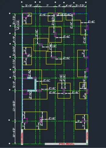
- From the layer properties make another new layer as grid lines and making line as ISO long-dash short-dash.
- Selecting dash line type the XLINE command and make a line in horizontal and vertical direction.
- Now from the vertical line give the offset of 5’9” in +x direction.
- Now give the offset of 2’ in same direction.
- Now give the offset of 7’ in same direction.
- Now give the offset of 4’ in same direction.
- Now give the offset of 4’6” in same direction.
- Now give the offset of 5’7.5” in same direction.
- Now from the upper horizontal line give the offset of 5’7.5” in -y direction.
- Again give the offset 3’7.5” in the same direction.
- Again give the offset 4’9” in the same direction.
- Again give the offset 5’10.5” in the same direction.
- Again give the offset 5’7.5” in the same direction.
- Again give the offset 3’9” in the same direction.
- Again give the offset 5’9” in the same direction.
- Again give the offset 13’10.5” in the same direction.
- Again give the offset 10’4.5” in the same direction.
- Now from the top most horizontal grid line give the offset of 4.5” in +y direction.
- Now from the left vertical grid line again give the offset of 4.5” in +x direction.
- Now from the opposite vertical grid line give the offset of 9” in +x direction.
- Boundary has been made.
- Take left most vertical line as A and top horizontal grid line as 1.
- From the internal boundary and upper boundary make a column of 24”x24” with the help of line command.
- From the lower and left vertical line of column give the offset of 3’ and 2’ using OFFSET command.
- Join the lines using line command.
- Use TRIM command for trimming the lines wherever required.
- Footing space has ben made.
- Make a column of 9’x18’ from the intersection point of D,1.
- From the intersection point use line command LINE and give the command as 9” in +x direction
- Now give the command as 9” in –y direction.
- Now give the command as 18” in –x direction
- Now give the command as 9” in +y direction.
- Now give the command as 4.5”in +x direction.
- Column is made.
- Now for footing portion give the offset of 2’6” from both the vertical line of the column.
- From the lower line of column give the offset of 3’ in –y direction.
- Join the line using line command by keeping ortho on.
- Footing space has been made.
- Make rest of the columns and footing space like this only as all the columns are made from the intersection points of grid lines.
- Footing space is made with the help of offset command by giving the required distance as mentioned.
- Now for making the brick wall give the offset of 4.5” on both the side for getting 9” brick wall.
- Use single line text for labelling and do the dimensioning.
- Use the Hatch command for brickwall to show separately
- For hatching boundary should be closed.
- Use the layer properties for assigning the different colour properties to the lines.