Creating a Wardrobe detailed drawing, Floor Plan, Kitchen Layout and Column Detail using AutoCad
QUESTION NO -1
ANSWER:
AIM: - Draw the elevation and details of a wardrobe as shown in the Figure below . after sketching , if need to provide the dimentions and texxt with the use of layers.
INTRODUCTION: IN this drawing we have to draw the elevation details of wardrobe and All dimention given in mm and use proper text style and dimentions method
PROCEDURE:
FOR START ANY DRAWING FIRST OF ALL WE HAVE TO DO SOME SETTINGS ACCORDING THE DRAWING -
SETTINGS - OPEN AUTOCAD
- SET DEFAULT SETTINGS - METRIC [MM]
- SELECT A TEMPLATE - ACCORDING TO DRAWINGS
- SELECT A WIZAED - ADVANCED SETUP
- UNITS - DECIMAL, PRECISION -0
- ANGLE - DECIMAL DEGREES
- ANGLE MEASURE - ACCORDING TO PLAN
- ANGLE DIRECTION - COUNTER CLOCKWISE
- AREA - ACCORDING TO PLAN
After this enter "D" for dimetion unit and set primary unit DECIMAL set precision 0
MODES -
- GRID ON BY F7 'CONTROL+G'
- USE ORTHO MODE FOR STRAIGHT 90 DEGREE ACCRDING NEED(F8)
- ON POLAR TRACKING (F10) SET ANGLE (15,30,45)
- OBJET SNAP TRACKING (F11)
- OBJECT SNAP (F3)
- TRANPARANCY ON WHEN YOU NEED
TO DRAW THE LAYOUT PLAN WE FOLLOW THE FOLLOWING STEPS : -
STEP -1
- To start the drawing firsty set the unit in 'mm'
- take construction line and draw horizontaly and vertically .
- In the command bar take offset of 2800 and 2600 respectively vertically and horizontaly .
STEP -2
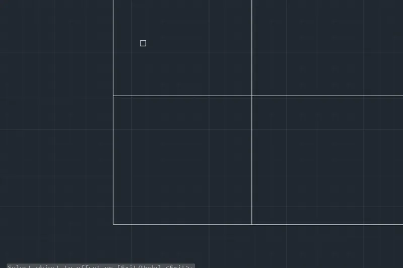
- In the command bar take offset of 12 mm and take is from bottom line and take 488 mm from last offset
- take offset 100 mm from the bottom line.
STEP -3
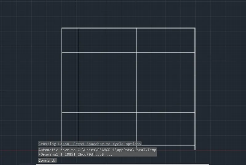
- for divided the box take offset 608 mm from last horizontal line 4 times
- take attach the corner point with the help of line command.
STEP -4
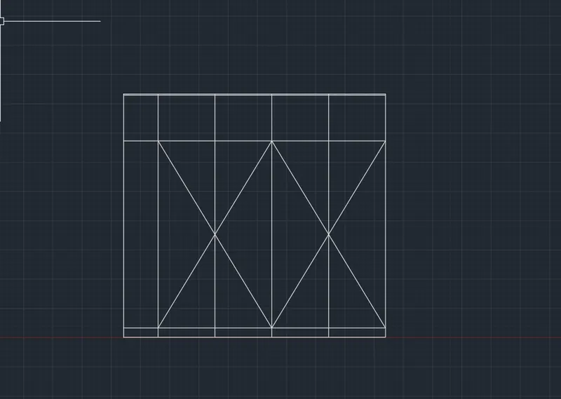
- With the help of trim or erase command trim the all unwanted lines .
- With the Help of Dimention command show all the dimention and after one time dimention take dimcontious for continuethe next dimention.
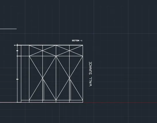
- With the help of trim or erase command trim the all unwanted lines .
- With the Help of Dimention command show all the dimention and after one time dimention take dimcontious for continuethe next dimention.
STEP -5
- To draw this shap take line with 2800 mm horizontaly and 2600 mm vertically
- take 12 mm offset and with the help of offset command make rectangle 2800 x 2600
- take offset 508 from top to bottom.
- again take offset 1180 from last offset
- again take offset 900 from last offset.
- next take offset vertically 365 from first verticall line than take offset 1200 from last offset
- again take offset 1223 from last offset and draw 12mm offset every line.
- with the help off offset command take offset of 300 from 2nd horizontal line from upper side.
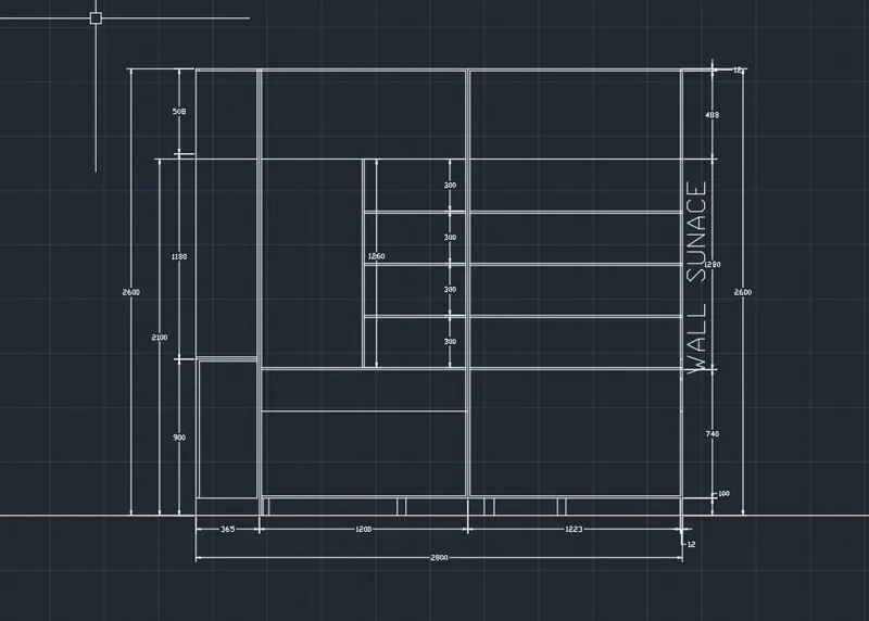
- With the help of trim or erase command trim the all unwanted lines .
- With the Help of Dimention command show all the dimention and after one time dimention take dimcontious for continuethe next dimention.
STEP -6
- For this shape take line command and put horizontally.A
- After this take three verticall line of 2600 mm with the distance off above 1000mm and take 12 mm from top to bottom.
- first line distance is 365mm second line distance is 630 and third line distance is 630 respectively
- take 100 mm offset from bottom. and take offset 900 mm from the last offset.
- than take 900 from last offset.
- again take offset command in the center box and take offset 300 fourtimes upward direction.
- with the help of offset command take 12 mm offset which is required.
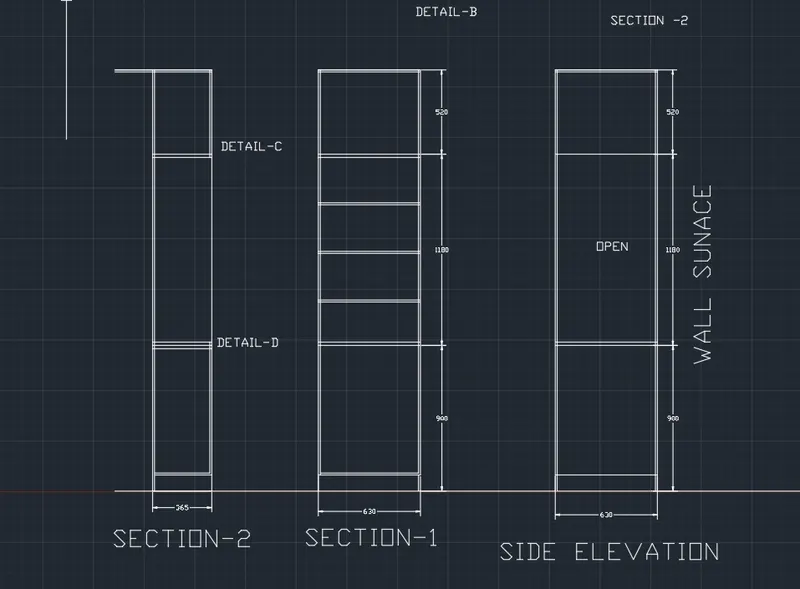
- With the help of trim or erase command trim the all unwanted lines .
- With the Help of Dimention command show all the dimention and after one time dimention take dimcontious for continue the next dimention.
STEP -7
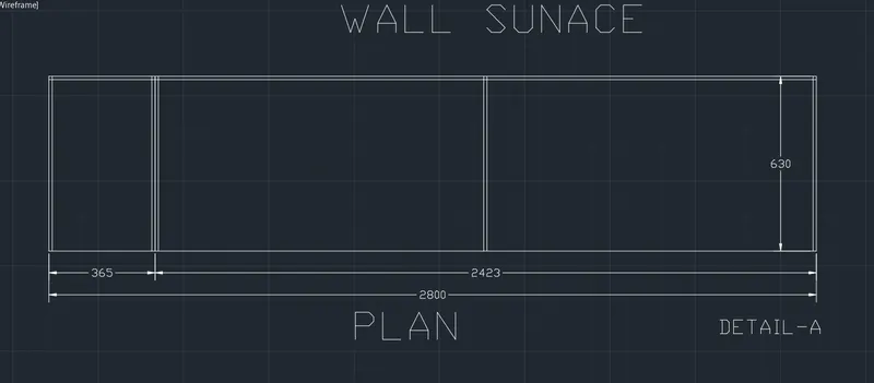
- For this shpe take line 2800 mm and vertical 630 mm
- take offset 12mm from upward to dounward direction
- take vertical line wiht the corner take offset 365 from corner line than again take offset of 2423mm and make center line of this box
- take 12 mm offset if required.
STEP -8
- Use Text command to give the plan details
- With the help of trim or erase command trim the all unwanted lines .
- With the Help of Dimention command show all the dimention and after one time dimention take dimcontious for continue the next dimention.
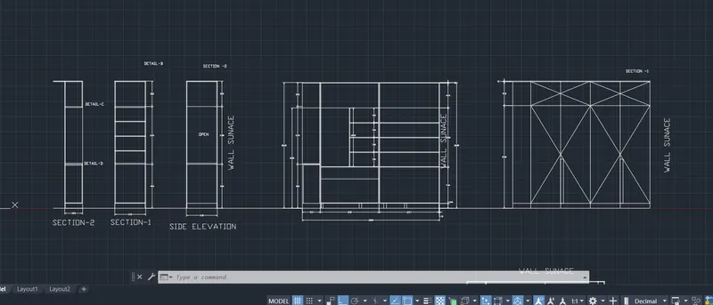
RESULTANT DRAWING:
QUESTION NO. -2
ANSWER:
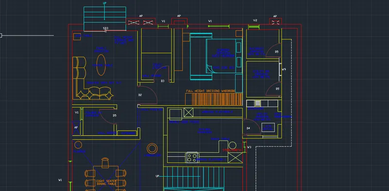
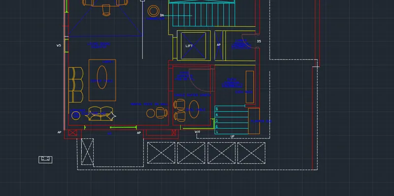
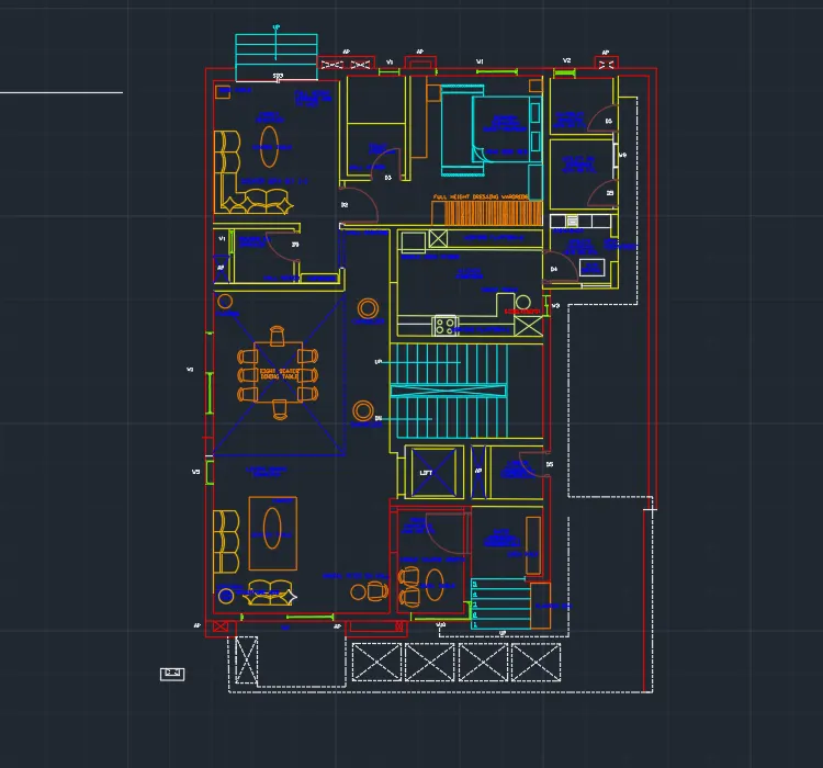
AIM: -Draw the floor plan as shown in the Figure. Use the proper drafting tools to sketch the plan. Do not hatch or draw the furniture. You need to draw the floor plan with the following.
INTRODUCTION: WE HAVE TO also import the Floor_Plan.pdf into our current drawing and start working on the project. You need to scale the imported pdf file using reference option. All dimensions are in mm.
Walls (Exterior and Interior Wall Thickness: Exterior Wall- 230mm, Interior Wall: 150 mm (Wherever Required)
Doors and Windows: Assume the size of the doors and window. Stairs Tread-300mm, Riser-150mm Insert Text wherever required Insert the dimensions using proper dimension techniques
LINK OF FILE IS ATTACHED
https://web.autocad.com/acad/me/sid/shares/drawings/acf17509-2f9f-46fb-8601-c56a78510e2d/editor
PROCEDURE:
FOR START ANY DRAWING FIRST OF ALL WE HAVE TO DO SOME SETTINGS ACCORDING THE DRAWING -
SETTINGS - OPEN AUTOCAD
- SET DEFAULT SETTINGS - METRIC [MM]
- SELECT A TEMPLATE - ACCORDING TO DRAWINGS
- SELECT A WIZAED - ADVANCED SETUP
- UNITS - DECIMAL, PRECISION -0
- ANGLE - DECIMAL DEGREES
- ANGLE MEASURE - ACCORDING TO PLAN
- ANGLE DIRECTION - COUNTER CLOCKWISE
- AREA - ACCORDING TO PLAN
After this enter "D" for dimetion unit and set primary unit DECIMAL set precision 0
MODES -
- GRID ON BY F7 'CONTROL+G'
- USE ORTHO MODE FOR STRAIGHT 90 DEGREE ACCRDING NEED(F8)
- ON POLAR TRACKING (F10) SET ANGLE (15,30,45)
- OBJET SNAP TRACKING (F11)
- OBJECT SNAP (F3)
- TRANPARANCY ON WHEN YOU NEED
TO DRAW THE LAYOUT PLAN WE FOLLOW THE FOLLOWING STEPS : -
SOME OTHER DATA :-
- EXTERIER WALL THICKNESS - 230MM
- INTERIOR WALL THICKNESS - 150MM
- DOORS AND WIINDOW :D1 - 1220MM
D2 - 1065MM
D3 - 915MM
D4 - 850MM
D5 -792MM - STAIRE TRED -300MM RISER -150MM
STEP -1
SNAPPY TABLE:
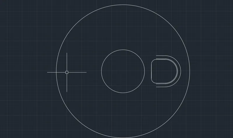
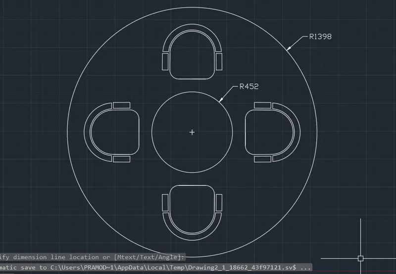
- WITH the help of curcle command DRAW CIRCLE WITH 1428MM DIA.
- also dra internal circle, and make a chaire. out side this with the help of line arch and trim command
STEP -2
- use array command to make multiple objects in this figure i have to take polar array command because circle is polar.
STEP -3
FAMILY
- For draw this plan we sholud want to line command and draw XL vertically and horizontally .
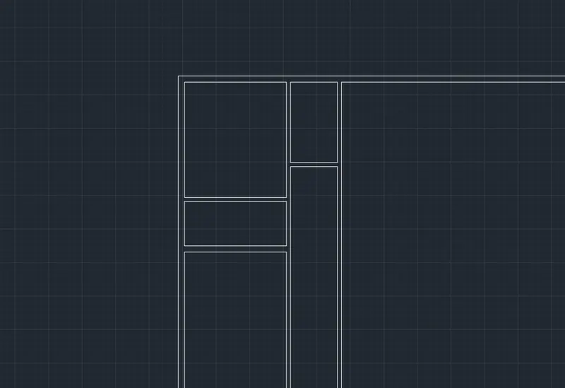
- take offset 230mm from vertically and horizontally to make outer wall .
- For corner room take offset 3880 from vertical line and 4350 from horizontal line and take offset 150 mm to draw internal wall of this
STEP -4
SIDE AND BOTTOM TOILET
- take line command and draw toilet portion of distance is 1750 x 3000 mm meke this with offset comman. DRAW V1 ventilation
- After this take offset of 1650 from up to down to make second toilet of this room this is bottom side from the draw V1 ventilation
- WITH THE HELP OF TRIM COMMAND TRIM THE ALL UNWANTED LINE.
STEP -5
BEDROOM AND UTILITY
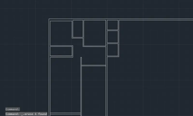
- After this we will draw the bedroom of 3880 x 4500 mm this draw with offset command off 3880 horizontal and 4500 verticall from toilet portion and give wall thickness 230mm vertically and horizontally.
- again take offset command and take offset 1900 to draw.
- MAKE D.H. toilet and utility room with the help of line and offset command.
STEP -6
KITCHEN
- After this make kitchen and for draw the kitchen take offset 4300 from upper to bottom and 3200 mm from utility wall
- give exterior wall thickness 230mm and interior wall thickness 150mm.
STEP -7
DINING AND LIVING AREA
- Again take ofsset 9710 mm downward from dining area and living area. offset 5310 from vertiicle line to draw this area
- use trim , extend command to modify the object.
STEP -8
STAIRE PORTION & LUMBER ROOM
- To draw the staire of the the plan take offset 1220 for lenght of stair and 300 mm open spece and again take 1220 for lenght of stairs.
- draw the lumber room with dimention is 1570 x 1600 .
- take offset 1600 from up to down and 1570 left to right
- Attach the door D5
- and draw AP-PORTION
STEP -9
LIFT PORTION
- Draw the lift portion of the plan
- for lift portion draw 1600 x 1600 mm squre.
- and put the space .
STEP -10
FOYER ,PATIO & OUTER STAIRS
- TO draw the foyer take offset 2000 mm from horizontal and 3220 mm from verticle to downwward direction.
- Put the door Side D5 draw wall thickness 150 mm
- For patio portion take offset 2150 from vertical and 2100 from horizontal
- Draw the stairs with tread 300mm and make planter box outside of stair.
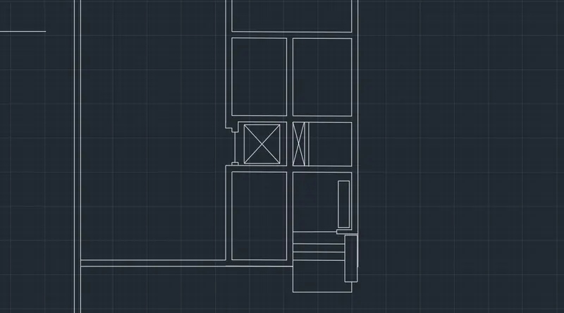
STEP -11
STAIRS
- TO draw stair take 1220 offset from lenght and give 300 tread for the stare case and provide landing
- for open space take line command and cross sing .
- use trim command to erase the unwanted lines and extend command for extend the line
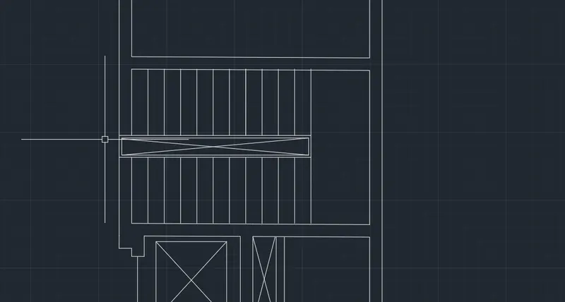
STEP -12
- draw door portion and window portion and other object like AP
- draw the other home objects like doors winow bed toilet seat , etc.
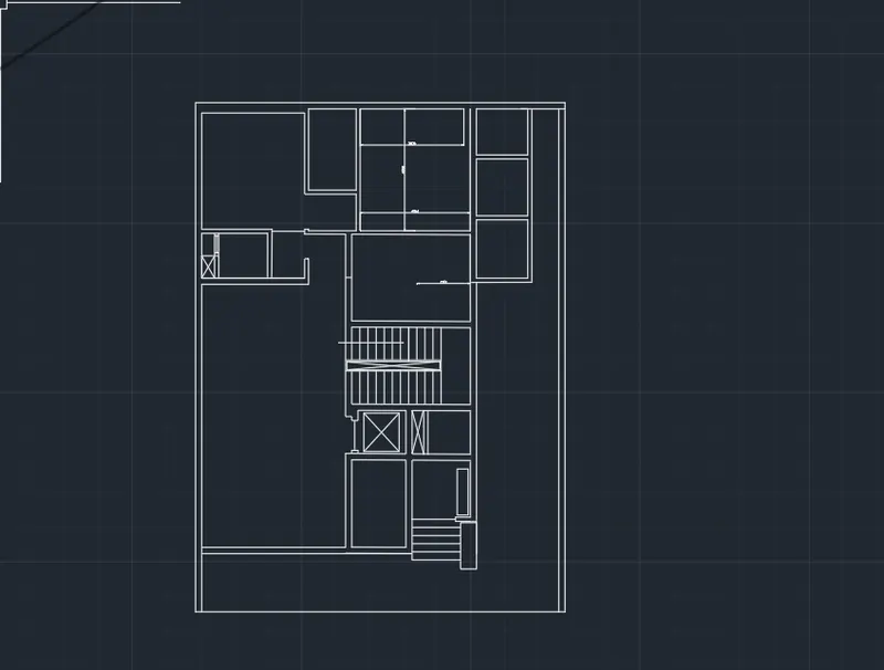
STEP -13
- Take Layer command for give particular color , line weight line type give the coolor and make layer to defined the object.
- The folowing layer are provided in this drawing.
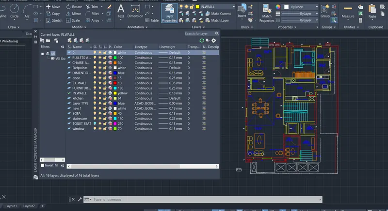
STEP -14
- Use Text command to give the plan details
- With the help of trim or erase command trim the all unwanted lines .
- With the Help of Dimention command show all the dimention and after one time dimention take dimcontious for continue the next dimention.
https://web.autocad.com/acad/me/sid/shares/drawings/acf17509-2f9f-46fb-8601-c56a78510e2d/editor
RESULTANT DRAWING:
single page formate:
QUESTION NO. -3
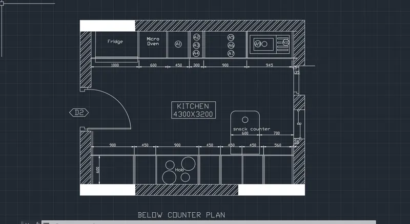
AIM: Create the Kitchen Layout as shown in the Figure below. Also, use proper dimension techniques to dimension the kitchen layout. Also, insert text wherever required. All dimensions are in mm.
PROCEDURE:
FOR START ANY DRAWING FIRST OF ALL WE HAVE TO DO SOME SETTINGS ACCORDING THE DRAWING -
SETTINGS - OPEN AUTOCAD
- SET DEFAULT SETTINGS - METRIC [MM]
- SELECT A TEMPLATE - ACCORDING TO DRAWINGS
- SELECT A WIZAED - ADVANCED SETUP
- UNITS - DECIMAL, PRECISION -0
- ANGLE - DECIMAL DEGREES
- ANGLE MEASURE - ACCORDING TO PLAN
- ANGLE DIRECTION - COUNTER CLOCKWISE
- AREA - ACCORDING TO PLAN
After this enter "D" for dimetion unit and set primary unit DECIMAL set precision 0
MODES -
- GRID ON BY F7 'CONTROL+G'
- USE ORTHO MODE FOR STRAIGHT 90 DEGREE ACCRDING NEED(F8)
- ON POLAR TRACKING (F10) SET ANGLE (15,30,45)
- OBJET SNAP TRACKING (F11)
- OBJECT SNAP (F3)
- TRANPARANCY ON WHEN YOU NEED
TO DRAW THE PLAN WE FOLLOW THE FOLLOWING STEPS : -
STEP -1
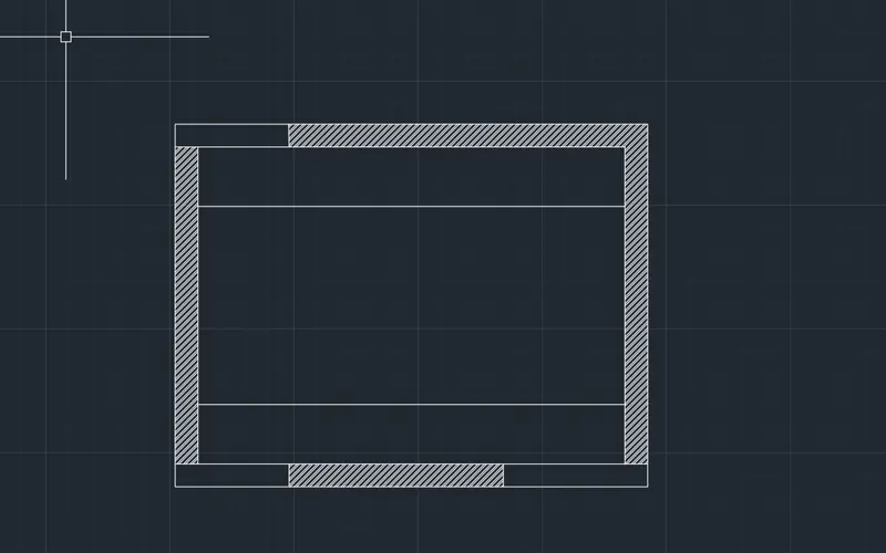
- To draw this shape take line command and draw a Kitchen size lenght 4300mm and width 3200mm
- take offset to draw wall details take offset 230 mm to draw wall.
- provide Hatch in the outer wall which is requied.
STEP -2
BELOW COUNTER PLAN:
- Take offset 600 mm from bottom to upward direction .
- take 12mm offset from last offset
STEP -3
- Take 600 offset from up ward to downward line.
- draw the kitchen object with the help of line command
- Use MText command to provide the text details
- Usev dimention and after this use Continues dimentoion from next dimension.
- draw all the obbject with given size.
STEP -4
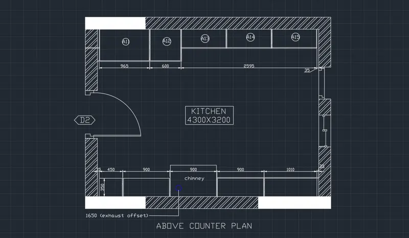
ABOVE COUNTER PLAN:
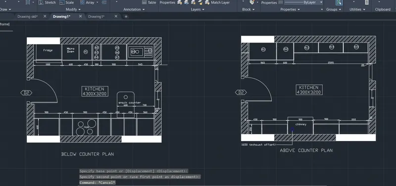
- fOR this plan copy the below plan and change the internal objects with the dimention
- and draw new objection provided dimention .
- use dim continue for provide the dimention.
STEP -5
- Use Text command to give the plan details
- With the help of trim or erase command trim the all unwanted lines .
- With the Help of Dimention command show all the dimention and after one time dimention take dimcontious for continue the next dimention
RESULTANT DRAWING:
QUESTION . -4
ANSWER:
AIM: Sketch the column details as shown in Figure. Insert dimensions and text in the figure. Refer to the bar sizes from the schedule.
PROCEDURE:
FOR START ANY DRAWING FIRST OF ALL WE HAVE TO DO SOME SETTINGS ACCORDING THE DRAWING -
SETTINGS - OPEN AUTOCAD
- SET DEFAULT SETTINGS -IMPERIAL [FEAT AND INCHES]
- SELECT A TEMPLATE - ACCORDING TO DRAWINGS
- SELECT A WIZAED - ADVANCED SETUP
- UNITS - ARCHITECTURAL
- ANGLE - DECIMAL DEGREES
- ANGLE MEASURE - ACCORDING TO PLAN
- ANGLE DIRECTION - COUNTER CLOCKWISE
- AREA - ACCORDING TO PLAN
After this enter "D" for dimetion unit and set primary unit ARCHITECTURAL
MODES -
- GRID ON BY F7 'CONTROL+G'
- USE ORTHO MODE FOR STRAIGHT 90 DEGREE ACCRDING NEED(F8)
- ON POLAR TRACKING (F10) SET ANGLE (15,30,45)
- OBJET SNAP TRACKING (F11)
- OBJECT SNAP (F3)
- TRANPARANCY ON WHEN YOU NEED
TO DRAW THE COLUMN PLAN WE FOLLOW THE FOLLOWING STEPS : -
STEP -1
- TO draw column plan take line command and draw the box 1'x1'
STEP -2
- with the help of line command draw line horizontally and make its part shown in figure.

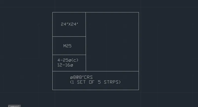
STEP -3
- Use MTEXT for write the column details , go to symbol option to insert the sing of phai.
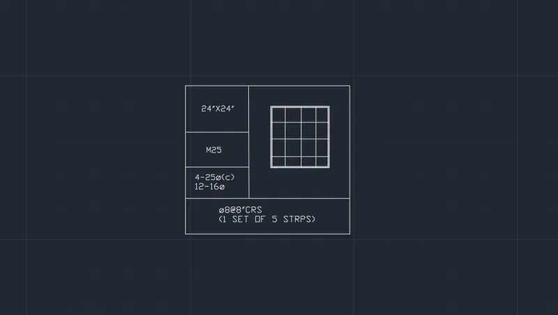
STEP -4
- draw the refrence column .
- use trim commnad to trim the unwanted line.
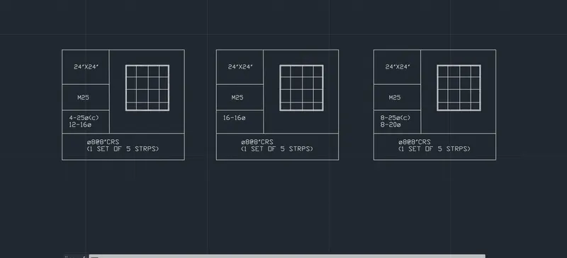
STEP -5
- Use copy command and copy the first drawing and past 2 times and change data with edit command.
- Use Text command to give the plan details
- With the help of trim or erase command trim the all unwanted lines .
RESULTANT DRAWING:
QUESTION NO. -5
ANSWER:
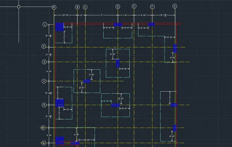
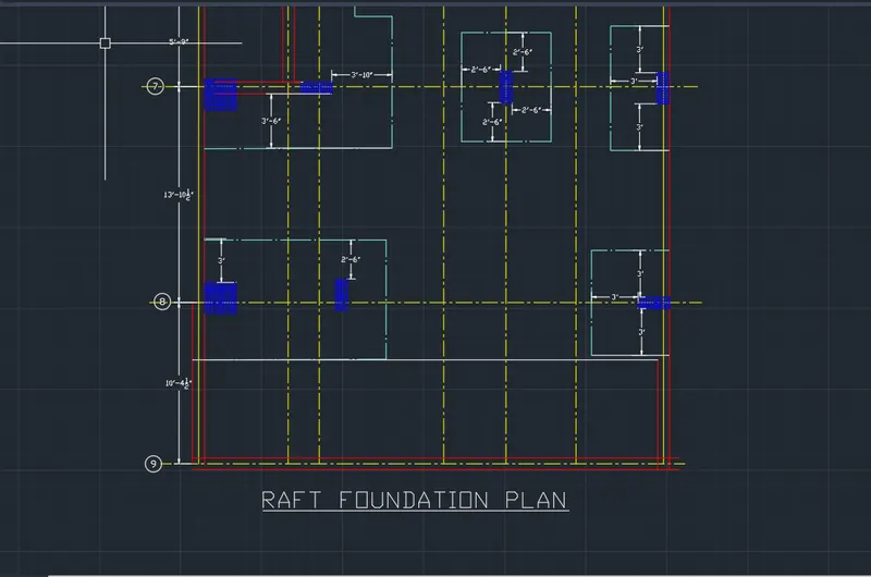
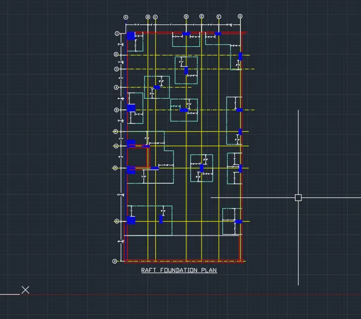
AIM: - Draw the Raft Layout as shown in the Figure. Assume the column size as per your knowledge.
INTRODUCTION: IN THIS PLAN WE can take the sizes as: 24”x24”, 9” x 24”, 9” x 18”, and 9’ x 24”. You can import the raft_foundation.pdf to ensure the missing dimensions.
PROCEDURE:
FOR START ANY DRAWING FIRST OF ALL WE HAVE TO DO SOME SETTINGS ACCORDING THE DRAWING -
SETTINGS - OPEN AUTOCAD
- SET DEFAULT SETTINGS -IMPERIAL [FEAT AND INCHES]
- SELECT A TEMPLATE - ACCORDING TO DRAWINGS
- SELECT A WIZAED - ADVANCED SETUP
- UNITS - ARCHITECTURAL
- ANGLE - DECIMAL DEGREES
- ANGLE MEASURE - ACCORDING TO PLAN
- ANGLE DIRECTION - COUNTER CLOCKWISE
- AREA - ACCORDING TO PLAN
After this enter "D" for dimetion unit and set primary unit ARCHITECTURAL
MODES -
- GRID ON BY F7 'CONTROL+G'
- USE ORTHO MODE FOR STRAIGHT 90 DEGREE ACCRDING NEED(F8)
- ON POLAR TRACKING (F10) SET ANGLE (15,30,45)
- OBJET SNAP TRACKING (F11)
- OBJECT SNAP (F3)
- TRANPARANCY ON WHEN YOU NEED
TO DRAW THE COLUMN PLAN WE FOLLOW THE FOLLOWING STEPS : -
LINK OF FILE IS ATTACHED
https://web.autocad.com/acad/me/sid/shares/drawings/0062ed27-1175-41e8-84c7-3f9382208b54/editor
STEP -1
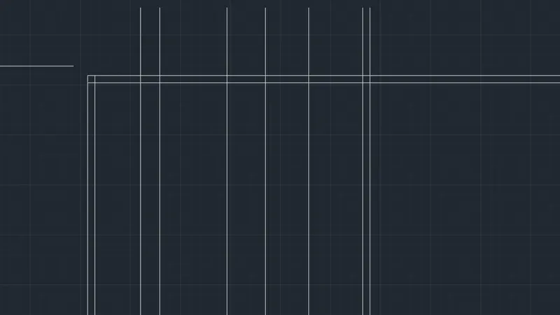
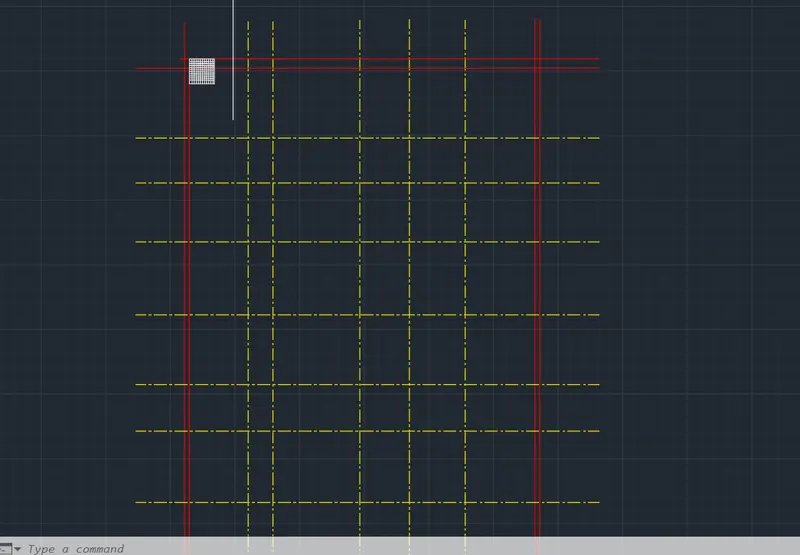
- Take Line command to draw the layout . firstly take construction line and put horizontally and vertically.
- take given offsets horizontally and vertically .
- use trim command to erase unwanted lines.
STEP -2
- Go to layer and set new layer center line , wall column and give line type and line weight according to layout
- draw column 24"x24" , 9"X24" AND 9"x18" and put it from the help of center line
- Before puting the column , go to multileader.
STEP -3
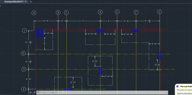
- Go to multileader command and set custum leader and give block formate.
- in horizontally center line and put the multileader in numbers 1,2,3,4,5,6,7,8,9 .
- GO to the Layer command and set the new layer for particular objects like wall , foooting column center line etc.
- set line type , line weight , and line color for layer properties .
STEP -4
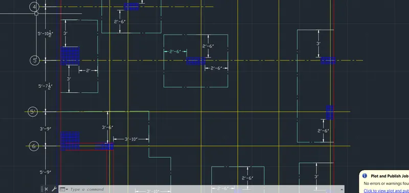
- in the center make all footing with 2'-6" offset and 3' with requred .
- draw all the fottings with the help of line command and offset command.
- WRITE IN horizontally A,B,C,D,E,F,G WITH THE HELP OF LEADER COMMNAD
STEP -5
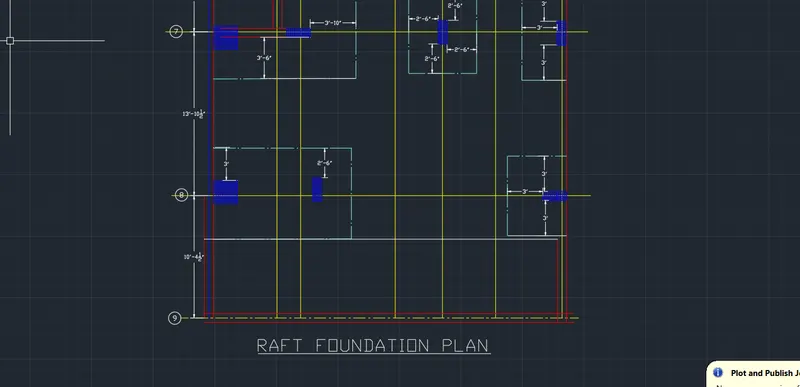
- Use Text command to give the plan details
- With the help of trim or erase command trim the all unwanted lines .
- With the Help of Dimention command show all the dimention and after one time dimention take dimcontious for continue the next dimention.
STEP -6
RESULTANT DRAWING: the final drawing attached with 2 screenshot .
Single Page format
RESULT:
COMPLETED ALL THE GIVEN DRAWING WITH THE GIVEN DATA AND DIMENTIONS . THE RESULTANT DRAWING OF THIS PROJECT IS ATTACHED.
RESULTANT DRAWING:
DRAWING NO. -1
DRAWING NO. -2
DRAWING NO. -3
DRAWING NO. -4
DRAWING NO. -5
LINK-
https://web.autocad.com/acad/me/sid/shares/drawings/0062ed27-1175-41e8-84c7-3f9382208b54/editor
ATTACHED FILE: