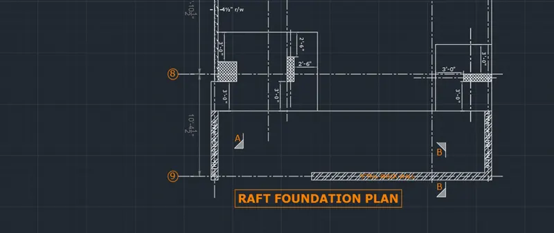
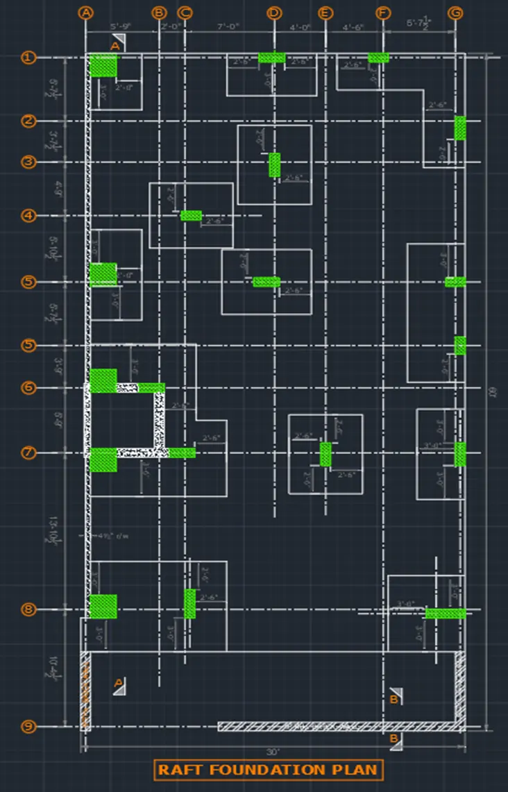
Creating a Wardrobe detailed drawing, Floor Plan, Kitchen Layout and Column Detail using AutoCad
Week 6-Assignment 6-Module 2
Aim: To sketch and edit the requested layout using the different drawing, modifying tools with application of advanced editing tools covered in week 6 sessions.
Introduction:
- The topics covered in week 6 (titled Create and Modify Annotations) which are essentials in plotting the requested geometries are as follows;
- Dimensions, the function in AutoCAD for measuring objects either the length, width, area or the volume that an object occupies. It is under Annotations Panel where you can find varieties of functions under the Dimension Toolbar such as Linear, Aligned, Arc Length, Angle, Radius etc.
- Dimensions (Arc Length), it measures the length of an arc. To create an Arc Length dimension, select object 1 then click point 2 to place the dimension line. Command line: To start the Arc Length Dimension tool from the command line, type “DIMARC” and press [Enter]. It comes with many options when enabled such as below.

- Dim Radius, it measures the radius of an arc or circle. To create a Radius dimension, select object 1 then, click point 2 to locate the dimension line. Command line: To start the Radius Dimension tool from the command line, type “DIMRAD” and press [Enter]. It comes with many options when enabled such as below.

- Dim Diameter, it measures the diameter of an arc or circle. To create a Diameter dimension, click object 1 then, click point 2 to locate the dimension line. Command line: To start the Diameter Dimension tool from the command line, type “DIMDIA” and press [Enter]. It comes with many options when enabled such as below.

- Jogged Dimensions, it measures the radius of an arc or circle but places the leader line in an alternative place (inferred point) to the arc or circles centre point. The jog indicates the dimension line doesn't point to the centre of the circle.
- Coordinate Dimensions, are used to locate the X or Y coordinate value of a point. Click point 1 to identify the point location, click point 2 to locate the dimension line. Ordinate dimensions are especially useful for elevations or OS grids which use specific coordinates.
- Dimension Break, it breaks the selected dimension leader line with a preset gap. The dimension used to calculate the gap is the current dimension style leader line offset. The gap is created twice the size on this offset, equally split either side of the break point indicated. Select the 'Break Dimension Line' button.
- Dimension Continue, this will let you continue to create dimensions from the last ordinate, angular, or linear created dimension, which lines up automatically.
- Baseline Dimensions, it measures the distance from a starting point to multiple other points. Baseline only works on an existing Linear or Aligned dimension. It takes the settings and height from the existing dimension chosen.
- Dim Jogline, it measures the radius of an arc or circle but places the leader line in an alternative place (inferred point) to the arc or circles centre point. The jog indicates the dimension line doesn't point to the centre of the circle.
- Dim Space, it Adjusts the spacing between linear dimensions or angular dimensions. The spacing between parallel dimension lines is made equal. You can also make the dimension lines of a series of linear or angular dimensions line up by using a spacing value of 0.
- Centerline, this tool will add a center line in between two parallel or non-parallel lines. To add a center line select the Centerline tool from Centerlines panel of Annotate tab and click on the two lines. The center line will be automatically added in between the selected lines.
- Quick Leader, Creates a leader and leader annotation.
- Quick Dimension, it automatically adds dimensions to your selected elements (including those in elevations and sections), creates multiple dimension chains at one go, and joins isolated dimensions into a chain. Automatically add dimensions to selected architectural, structural or mechanical elements.
- Revision Cloud, this is the geometries used in AutoCAD to drive attention of users to a certain part of the drawing. The revision clouds are Polylines in the shape of connected arcs and they can also be modified like a Polyline.
Procedure:
A. Starting AutoCAD;
- Search for the AutoCAD icon from your desktop and double click it to make it run or you may search it from windows search tool and open from there if no shortcut in the desktop.
- You may simply click the “Get Started-Start Drawing” icon once the AutoCAD is opened or you may click the Application Menu tab with the “A” AutoCAD logo on the top -left most side of the screen and select new. From the new you may find a variety of templates that suits your requirements.
- For this exercise, we will just simply proceed on Get Started-Start Drawing” icon and set up the measurement units inline with the drawing requirements.
B. Setting the Drawing Parameters;
- Set up the measurement units according to sketched information provided.
- To set up that, a much faster way is to type “units” in the command line and hit enter or space bar. The Drawing Units Dialog box will then pop up and measurement parameters will then set up in line with the requirements. Similar thing, you need to set up the dimension through the DDIM command.
- As for the gridlines, you may right click gridline icon in the status bar and go for the drafting settings. Under the Snap and Grid of the Drafting Settings Dialog box, you may set up the needed spacing of grids along its X and Y axis. “DS” command will also work to pop up the Drafting Settings Dialog box.
C. Starting the exercise;
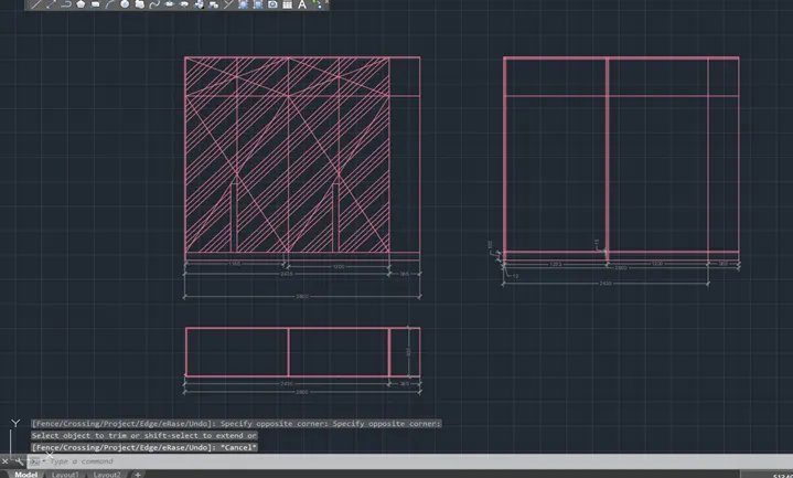
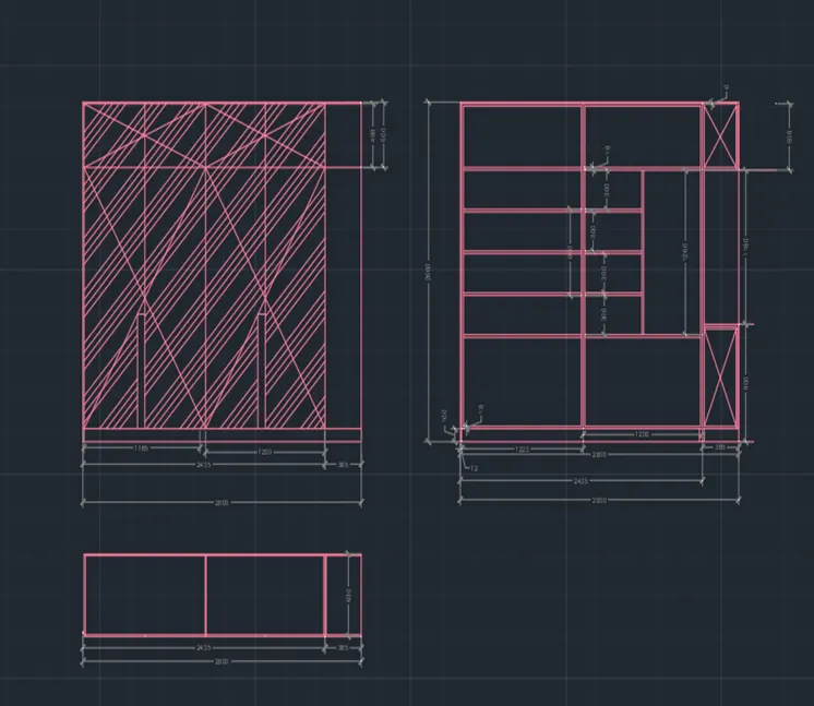
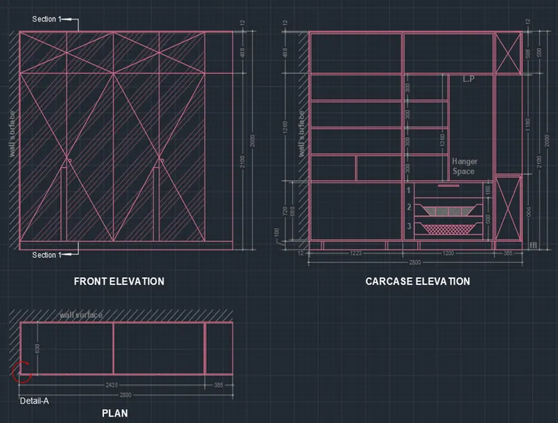
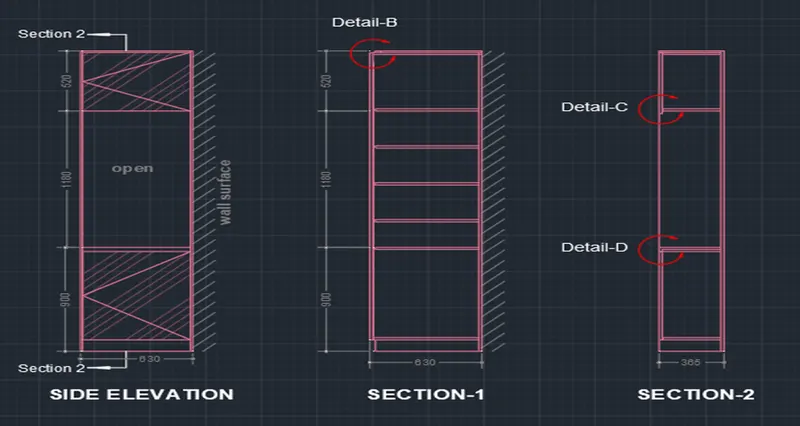
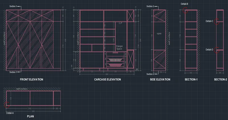
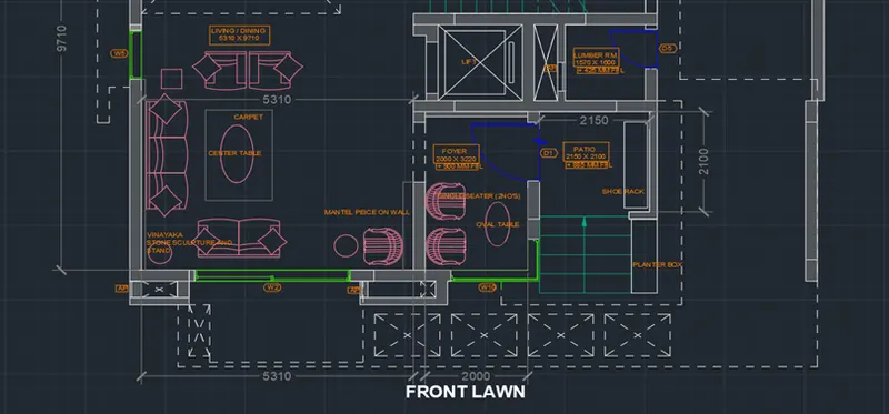
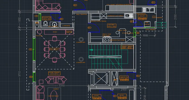
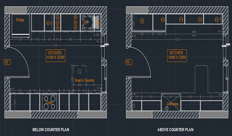
- Combination and manipulation of all the different coordinate entry methods, drawing and modifying tools learned from weeks 1 to 6 were being used here in the completion of all the exercises given and result as pasted below.
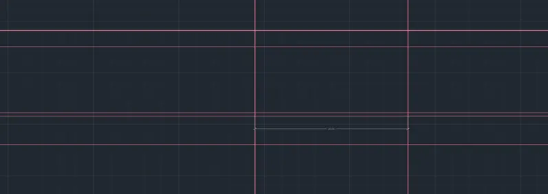
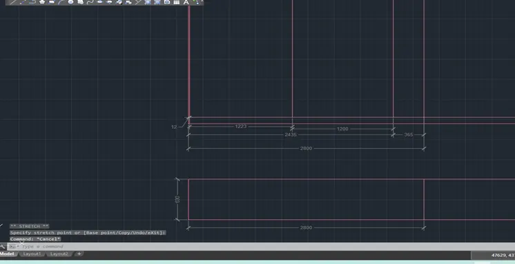
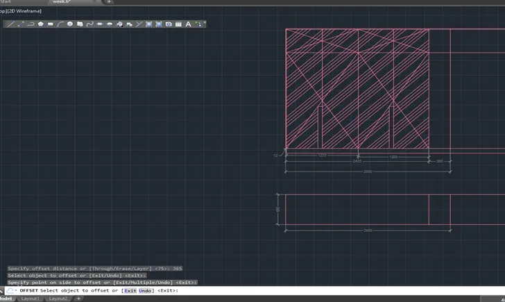
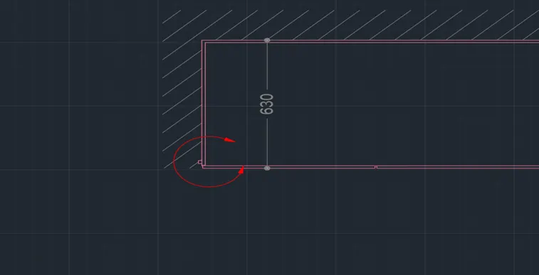
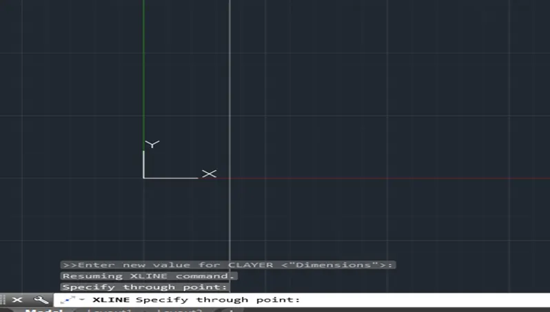
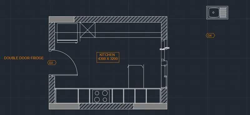
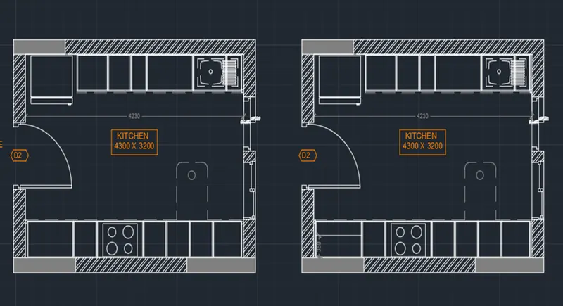
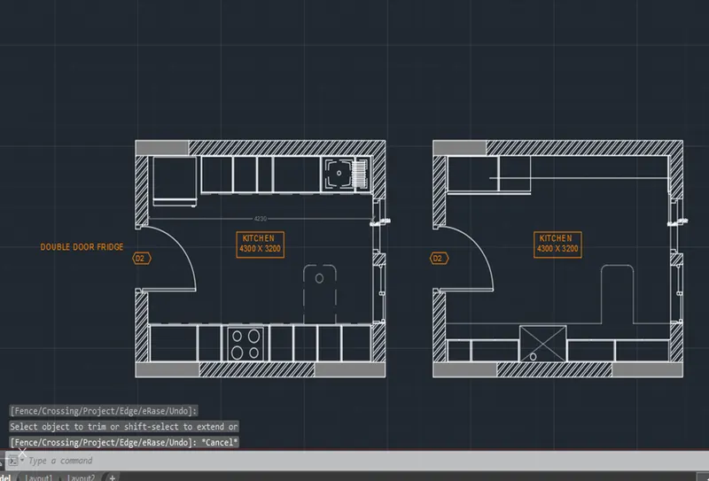
- I have attached some screenshots while plotting the needed five exercises to show the procedure on how it was done to come out with the requested layouts.
- Also some special commands and functions were being used in these exercises which are not covered in the sessions such as “PASTECLIP” and “PDF IMPORT”.
D. Challenge;
- In general, below commands/functions were being used while working on the exercises.
- Units
- LIMITS
- LIMMAX
- DDIM
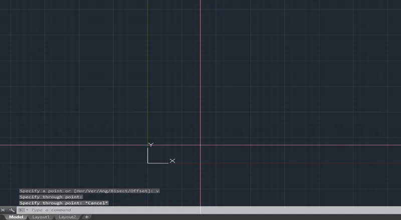
- XLINE
- LINE
- PLINE
- OFFSET
- DIVIDE
- PTYPE
- ARRAY (AR)
- MIRROR (MI)
- CIRCLE
- TABLE
- FILLET
- TEXT
- MTEXT
- DTEXT
- LEADER
- Manipulation with Ortho mode and Object Snaps
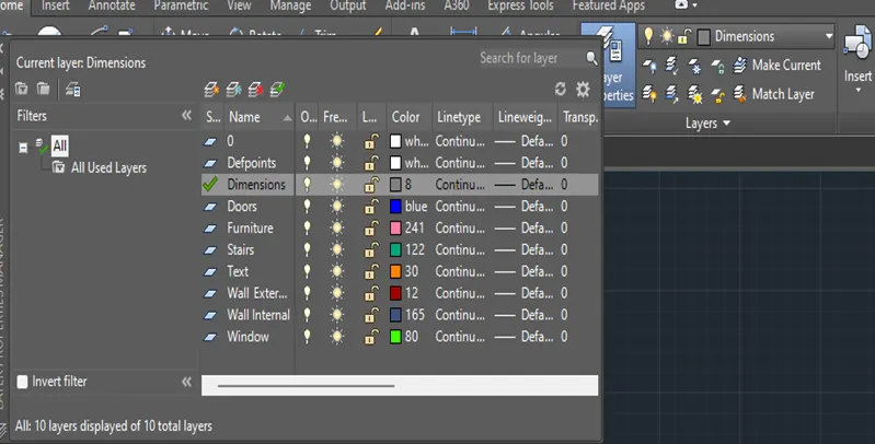
- LAYERS
- UTILITIES
- MATCHPROP
- ANNOTATION
- PASTECLIP
- PDF IMPORT
- RAY
- DIMBREAK
- COPY
- HATCH
- SCALE
Challenge 1;
Loading my own created template
Challenge 2;
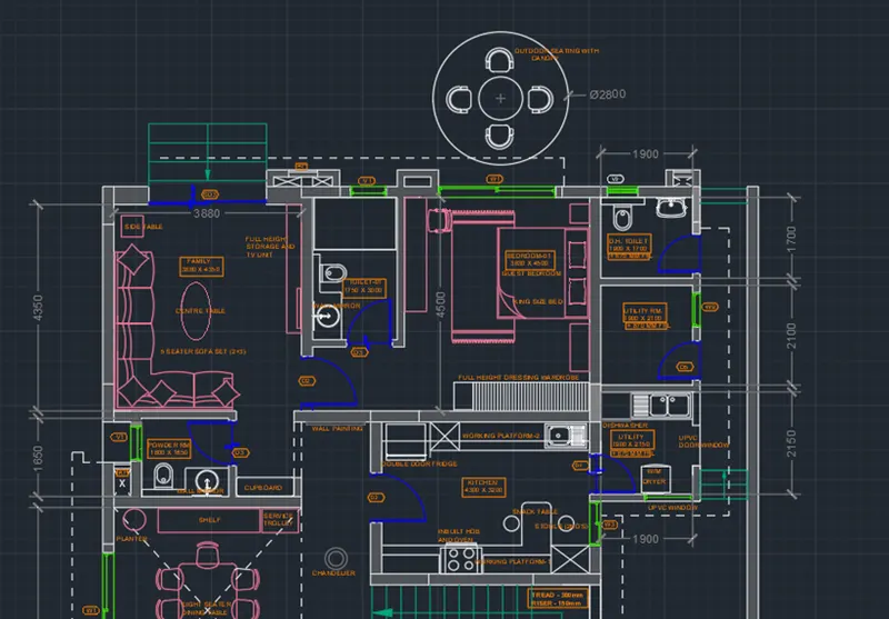
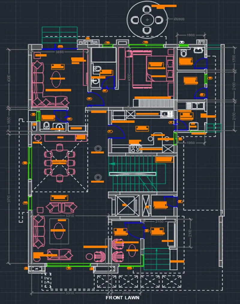
Challenge 3;
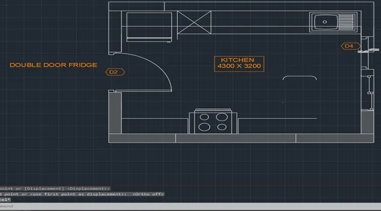
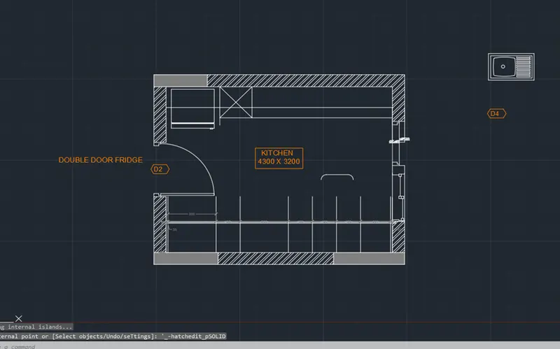
Challenge 4;
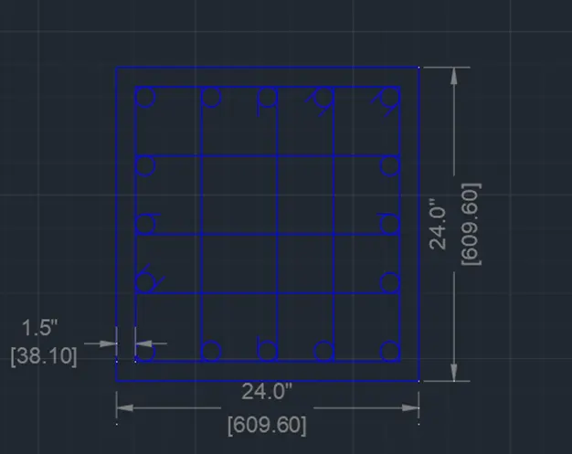
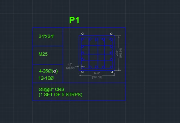
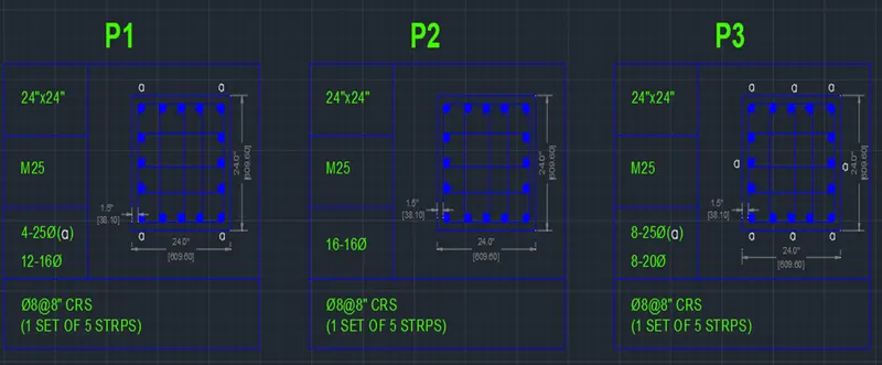
Challenge 5;