Creating a Wardrobe detailed drawing, Floor Plan, Kitchen Layout and Column Detail using AutoCad
AIM: To draw the Drawing sections as per the mentioned properties below along with arbitrary configuration matching with the needs to complete the following sketches:
(a). Draw the elevation and details of a wardrobe as shown in the Figure below. After sketching, you need to provide the dimensions and text with the use of layers. Use proper text styles and dimension methods to document it. Also, assume dimensions, wherever needed.
Note: All dimensions are in mm.
(b). Draw the floor plan as shown in the Figure. Use the proper drafting tools to sketch the plan. Do not hatch or draw the furniture. You need to draw the floor plan with the following
Walls (Exterior and Interior Wall Thickness: Exterior Wall- 230mm, Interior Wall: 150 mm (Wherever Required)
Doors and Windows: Assume the size of the doors and window.
Stairs: Tread-300mm, Riser-150mm
Insert Text wherever required
Insert the dimensions using proper dimension techniques.
(c). Create the Kitchen Layout as shown in the Figure below. Also, use proper dimension techniques to dimension the kitchen layout. Also, insert text wherever required. All dimensions are in mm.
(d). Sketch the column details as shown in Figure. Insert dimensions and text in the figure. Refer to the bar sizes from the schedule.
8mm ---- 0.31 Inches
25mm--- 1 inches
16mm—0.62 inches
(e). Draw the Raft Layout as shown in the Figure. Assume the column size as per your knowledge. You can take the sizes as: 24”x24”, 9” x 24”, 9” x 18”, and 9’ x 24”. You can import the raft_foundation.pdf to ensure the missing dimensions.
INTRODUCTION:
- FIRSTLY, define the units required for drawing with precision using "UN" command.
- after defining the units with precision, assign the origin before proceeding further.
- Here I have defined the units in architectural form (Feet, inches) with precision of 0.000 having lightning option of generic form.
- I have approximated the data of column/footing configuration as given below:
- Every ring of stirrup has only one hook whose configuration is shown in figure (a) with a dimension of >2" at 135degree angle.
- use "merge" option where ever require to combine rows or column in the table attached below.
- Define the table properties from annotate command in the home tab & make the arrangement as per the need of the drawing.
8. Always aware to provide a scale to a particular type of drawing otherwise it may cause irregularities in the preceding sketch while switching over to next drawing with exaggerated/minimal scale option
| ELEMENTS OF STRUCTURE | DIMENSION(IN mm) | in inches" |
| Clear cover | 25 | 1" |
| inner wall/outer wall | 150/300 | 5"/10" |
| stirrups r/f | 8 | 0.33" |
| Longitudinal r/f dia. | 16 | 0.67" |
| 20 | 0.8" |
PROCEDURE:
FIGURE(a):
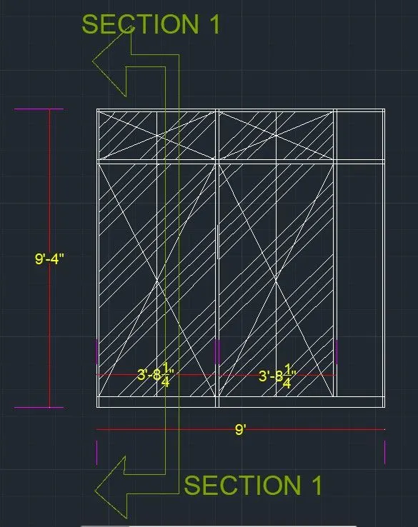
- use Line command to draw the above section nested with trace command.
- Offset are provided in the above sketch as follows;
Bottom border: 4"
inner/outer border: 0.75"/1"
- Use Dim-linear command to label the section.
- Adjust the properties of lines, arrows & symbols, text, primary units etc. using ANNOTATE command for labelling & dimensioning the sketch.
- Select the Hatch pattern from the "HOME" tab to lodge the section.
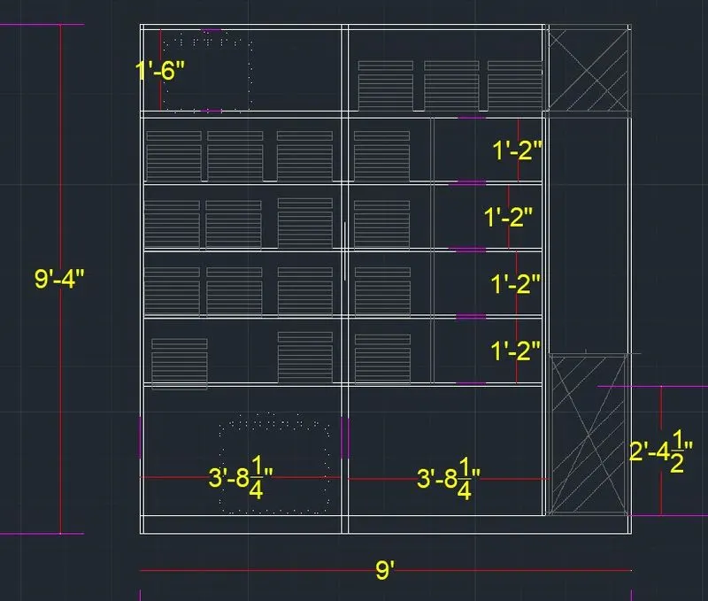
- Using line command nested with TRA command to draw the above sketch.
- Here I have drawn the doors & interior belongings through GREY Colour.
- Interiors partitions are offseted with 0.75" except middle partition of 1".
- I have labelled every partition of wardrobe instead of defining here every step.
- Properties used as follows:
Lines: red, Extension lines: Magenta
Offset from dimensioning lines: 2"/6"
TEXT: 9", FONT: ARIAL; Colour: yellow
arrows & symbols= datum triangle filled on both sides with 1" dimensions.
PRIMARY UNITS: architectural (Feet/Inches); precision: 0'00"
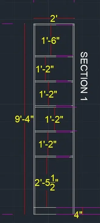
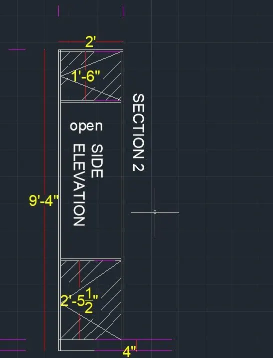
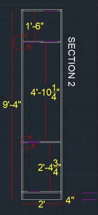
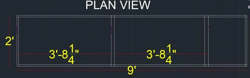
above sketches are drawn using ray command to get the uniformity in the sketch.
After using ray, we trim the unnecessary lines using tr command.
FIGURE(b):
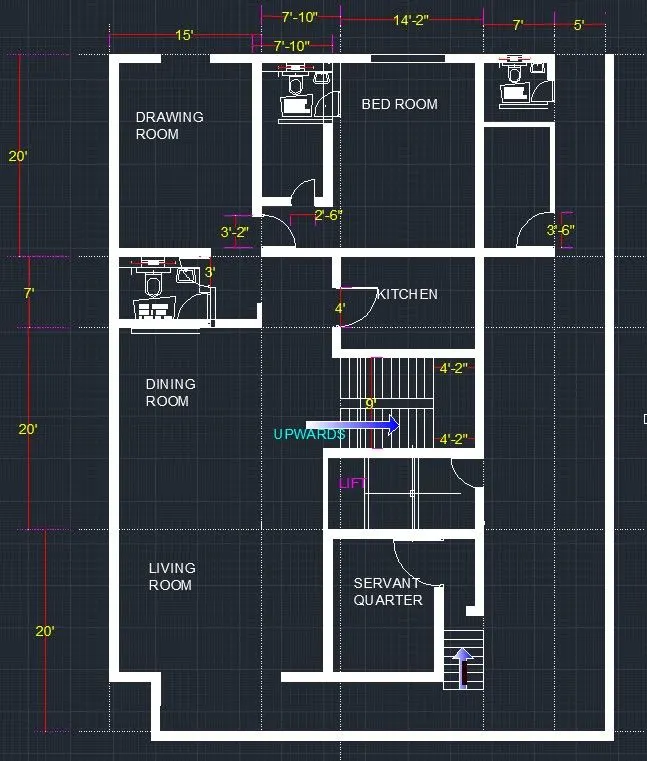
firstly, draw the grid lines with neat labelling before proceeding for sketching.
- Using Line command, Draw a line of 20' at left-hand side on the top of the attached page above.
2. Draw a line of 7' in the proceeding of above-mentioned line with same thickness of 10".
3. Draw a line of 20', followed by 20' line with same properties of lines as mentioned above.
4. take a 90degree turnout, draw a line of 15', followed by 7',15',7' and then by 5'.
5. Draw a line of 67' with an offset distance of 10" with 90degree turnout from the preceding line at the top-right of image.
6. Draw a line of 47' with an offset distance of 10" from the above- mentioned line in the 90dedree turnout at the back side of this plan.
7. it’s better to draw the staircase section at different location from the drawing and then same is located at the required position using move command.
8. After drawing the above lines, all are offseted with a distance of 10", followed by debugging the sketch using either TR command or Delete option.
9. Stair-case is drawn with Riser of 6" and thread of 10" using copy & mirror command.
10. Inner walls or partition walls are drawn with 5" dimension.
11. Doors are standardised with frame and then copied at different location using Block command using sway in any direction by defining parameter, actions & parametric constraints in block editor option.
12. Use insert command to enter the foreign object into the drawing.
13. after drawing this sketch, Labelling & texting would be done after adjusting the properties mentioned in the attached screenshots above.
figure(c):
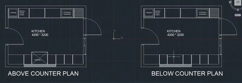
1.Use line command, Draw the lines of 1600mm on both sides of left entrance door of 1000mm, followed with 4300 mm lines on both sides parallel to counter after turning 90degree.
- From the preceding line, draw the line of 600mm & 1800 mm on the top right & bottom right side respectively on either side of 800mm door at right door entrance.
- here, we have drawn the walls through an offset of 300mm.
- Counters are drawn parallel to walls of 4300 mm dimension with a width of 600mm on both sides.
- counter are bifurcated into two portions of 450 & 900mm except with utensils washing section of 1350mm(900+450).
- Doors are standardised and then placed using move/copy + scale command.
FIGURE(d):
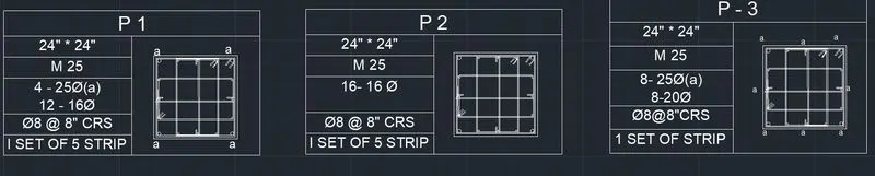
1. Sketch the section using line command nested with TRA command.
- Speculated Configuration are introduced in the introductory part to get the above sketch.
- Here we select the table option.
- define the table properties & use merge option to merge the required cells.
- Use Move command to outfit the section in next column to specification in every table.
- Arrangement of stirrups have a meaningful engineering in the above table.
FIGURE(e):
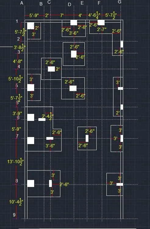
FIGURE(e):
1.Firstly, GRID LINES are marked on the plan at right angle to each other with proper dimensioning & labelling.
- After marking the Grid lines, start the sketch from one side using line & tr command.
- Lines are drawn in the attached screenshot above to guide the persuader to explain the details.
- Use rec command with TRA command to draw the footing section plan around the column cross-section.
- HERE, Column section are configured into three types as(9"*24"; 9"*18"; 24"*24") which can be chosen by visualisation i.e. why not configured.
- Outer walls are of 9" dimension.
7. After Drawing as per above sketch, hatching pattern can be chosen. (Here, selected one is solid, BYLAYER).
8.After Hatching the column section, Label the sketch to have a meaning to the reader along with texting.