Creating a Wardrobe detailed drawing, Floor Plan, Kitchen Layout and Column Detail using AutoCad
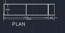
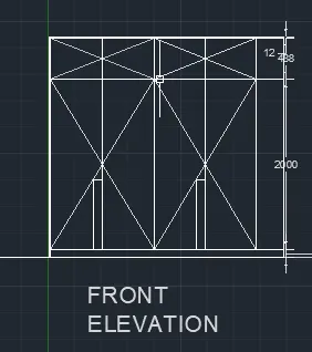
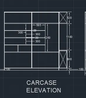
1. Draw the elevation and details of a wardrobe as shown in the Figure below. After sketching, you need to provide the dimensions and text with the use of layers. Use proper text styles and dimension methods to document it. Also, assume dimensions, wherever needed.
Note: All dimensions are in mm.
A)
1.First open the autocadd new file.
2.Set the units to decimals.
3.According to the given dimensions draw the plan.
4. project the line from plan to the front elevation and with required dimensions draw the outside elevation of wardrobe.
5.Then from the front elevation reference lines so the we have to draw the carcase elevation so that to show the racks inside the wardrobe.
6.Then we have to draw the section-1 from the front elevation.
7.Then we have to draw the section-2 from the side elevation.
8.Then specify the required dimensions.
9.All dimensions should be in mm.
Q2. Draw the floor plan as shown in the Figure. Use the proper drafting tools to sketch the plan. Do not hatch or draw the furniture. You need to draw the floor plan with the following:
Note: You can also import the Floor_Plan.pdf into your current drawing and start working on the project. You need to scale the imported pdf file using reference option. All dimensions are in mm.
Walls (Exterior and Interior)
Wall Thickness: Exterior Wall- 230mm, Interior Wall: 150 mm (Wherever Required)
Doors and Windows: Assume the size of the doors and window.
2.1 Stairs: Tread-300mm, Riser-150mm
Insert Text wherever required
Insert the dimensions using proper dimension techniques
A)
1.First open autocad new drawing file.
2.Then set the units to decimals.
3.Then first draw the walls the outer walls of 230mm and inner walls of 150mm.
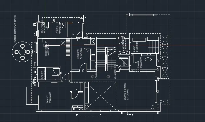
4.Then draw the doors and windows where ever required.
5.Then draw the stair case of dimensions of thread of 300mm and rise of 150mm.
6.Then specify the dimensions of the layout.
7.Then text the room dimensions and name of the rooms.
8.Then draw the outside seating canopy.
9.Then specify the dimensions and names.
Q3. Create the Kitchen Layout as shown in the Figure below. Also, use proper dimension techniques to dimension the kitchen layout. Also, insert text wherever required. All dimensions are in mm.
A:
1.First open new drawing file.
2.Then select the units to decimal units.
3.Then First draw the below counter plan.
4.Draw the fridge, microwave ,hub and some other counters.
5.Then specify the dimensions of the counters.
6.Then specify the names of the items below the counter.
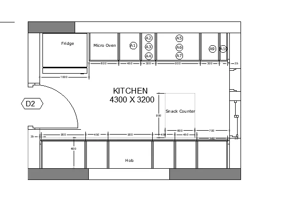
7.Then draw the columns, Walls ,doors, windows and sliding doors.
8.Then draw the above counter plan.
9.In this above counter there are cupboards, and chimneys.
10.Draw the cupboards and chimneys.
11. Specify the dimensions of the counters.
12.Then draw the columns, walls, doors,windows and sliding doors.
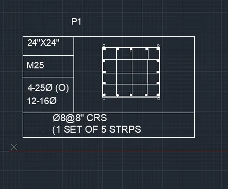
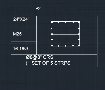
Q4. Sketch the column details as shown in Figure. Insert dimensions and text in the figure. Refer to the bar sizes from the schedule?
8mm ---- 0.31 Inches
25mm--- 1 inches
16mm—0.62 inches
A) 1.First open the new file of imperical units.
2.Then set the units to engineering units.
3.Then draw the columns of sizes 24"X24" the set of three.
4.First first set the rods of 4-25 dia and 12-16 dia.
5.For second set the rods of 16-16 dia.
6.For the third set the rods of 8 of 25 dia and 8 of 20mm dia.
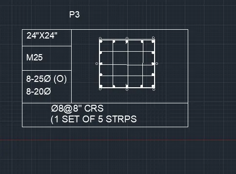
7.Set the boxes and write the dimensions and rods dia and numbers.
Q5. Draw the Raft Layout as shown in the Figure. Assume the column size as per your knowledge. You can take the sizes as: 24”x24”, 9” x 24”, 9” x 18”, and 9’ x 24”. You can import the raft_foundation.pdf to ensure the missing dimensions.
A:
1. First open new drawing of imperical units.
2.Set the units to architectural units.
3.First draw the center lines of ABCDEFG.
4.Of lengths 5'9",2',7',4',4'6",5'7 1/2".
5.Then Draw the centre lines of 123456789.
6.Of lengths of 5'7 1/2",3'7 1/2",4'9",5'10 1/2",5'7 1/2",3'9",5'9",13'10 1/2",10'4 1/2".
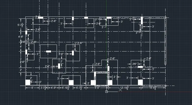
7.Then draw the rafts of desired lengths.
8.Then draw the columns on the rafts.
9.The draw the concerte beams and walls.
10.Then Specify the dimensions of the Rafts, center lines.
11.Then specify the dimensions of the layout.