Creating a Wardrobe detailed drawing, Floor Plan, Kitchen Layout and Column Detail using AutoCad
1.AIM
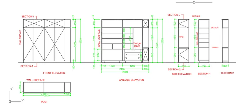
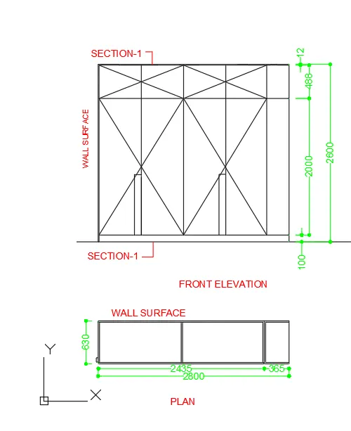
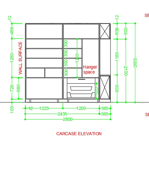
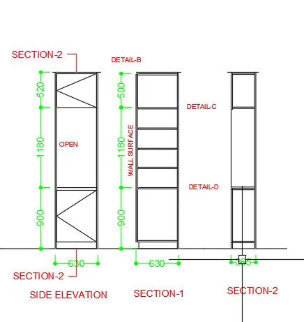
To draw the Elevation and Details of waredrobe using the various commands in Auto CAD.
PROCEDURE
- To create a new drawing sheet .
- Type ,,UN’ to set the units of current format of measure.( MILLIMETERS)
- Type ,,LIMITS’ to set the maximum dimension limits on the particular page.
- Type ,,L’ - Line commands allows to creating a line where the end points allows creating a line where the end points are dimensional co-ordinates.
- Type ,, OFF’ – offset command to create a new object that specified distance from an existing objects or through a specified points. ( For EX .. Dimensions of wall at interior and exterioir, staircase,,etc..,
- Type ,, FILLET’ to use the commands od rounding the objects with our specified radius.
- Type ,, Tr’ – Trim command is used to trims off an objects cutting the extra edges on objects.
- COPY – this commands is used to selected objects from a given square to destination, learning a copy at the originally selected location.
- ROTATE – rotate the objects around a specified point.
- MOVE – moves the objects to the destination place from the source place.
- TEXT – creates a text objects with specified height and orientation.
- Type ,, La ‘ to set the different layer properties of wall, door, window, slab, dimensions, text, etc.., for easily identified the different objects in the plan.
- Here we have to using the different layers properties of DIMENSIONS and TEXT.
- Finally, to save the drawing file.
RESULTS
The diagram of the given Elevation and Details oF Waredrobe is drawn as per dimensions using the software of
Auto CAD.
DIAGRAM
2.AIM
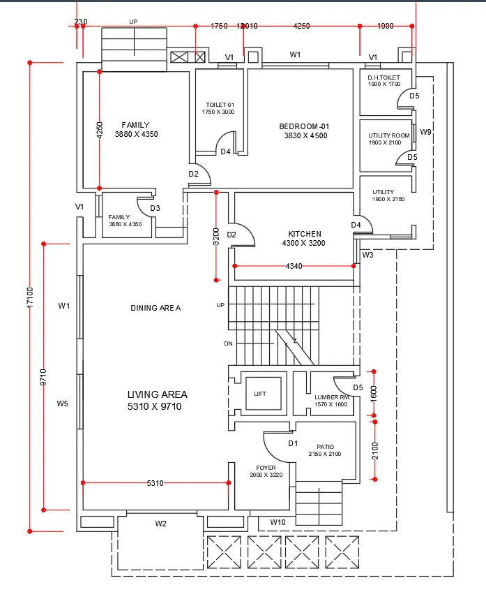
To draw the Floor plan using the various commands in Auto CAD.
PROCEDURE
- To create a new drawing sheet .
- Type ,,UN’ to set the units of current format of measure.( MILLIMETERS)
- Type ,,LIMITS’ to set the maximum dimension limits on the particular page.
- Type ,,L’ - Line commands allows to creating a line where the end points allows creating a line where the end points are dimensional co-ordinates.
- Thickness of the Interior wall is 150mm and Exterior wall is 230mm.
- Type ,, OFF’ – offset command to create a new object that specified distance from an existing objects or through a specified points. ( For EX .. Dimensions of wall at interior and exterioir, staircase,,etc..,
- Doors and Windows size are assumed to proper requirement.
- Staircase dimensions of Tread is 300mm and Riser is 150mm.
- Type ,, FILLET’ to use the commands od rounding the objects with our specified radius.
- Type ,, Tr’ – Trim command is used to trims off an objects cutting the extra edges on objects.
- COPY – this commands is used to selected objects from a given square to destination, learning a copy at the originally selected location.
- ROTATE – rotate the objects around a specified point.
- MOVE – moves the objects to the destination place from the source place.
- TEXT – creates a text objects with specified height and orientation.
- Type ,, La ‘ to set the different layer properties of wall, door, window, slab, dimensions, text, etc.., for easily identified the different objects in the plan.
- Here we have to using the different layers properties of DIMENSIONS and TEXT.
- Finally, to save the drawing file.
RESULTS
The diagram of the FLOOR PLAN is drawn as per dimensions using the software of Auto CAD.
DIAGRAM
3.AIM
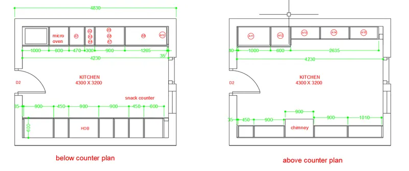
To draw the Kitchen Layout using the various commands in Auto CAD.
PROCEDURE
- To create a new drawing sheet .
- Type ,,UN’ to set the units of current format of measure.( MILLIMETERS)
- Type ,,LIMITS’ to set the maximum dimension limits on the particular page.
- Type ,,L’ - Line commands allows to creating a line where the end points allows creating a line where the end points are dimensional co-ordinates.
- Type ,, OFF’ – offset command to create a new object that specified distance from an existing objects or through a specified points. ( For EX .. Dimensions of wall at interior and exterioir, staircase,,etc..,
- Type ,, FILLET’ to use the commands od rounding the objects with our specified radius.
- Type ,, Tr’ – Trim command is used to trims off an objects cutting the extra edges on objects.
- COPY – this commands is used to selected objects from a given square to destination, learning a copy at the originally selected location.
- MOVE – moves the objects to the destination place from the source place.
- TEXT – creates a text objects with specified height and orientation.
- Type ,, La ‘ to set the different layer properties of wall, door, window, slab, dimensions, text, etc.., for easily identified the different objects in the plan.
- Here we have to using the different layers properties of DIMENSIONS and TEXT.
- Finally, to save the drawing file.
RESULTS
The diagram of the KITCHEN LAYOUT is drawn as per dimensions using the software of Auto CAD.
DIAGRAM
4.AIM
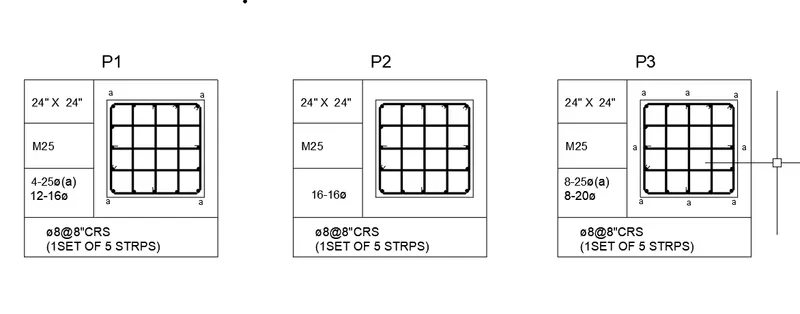
To draw the COLUMN Details using the various commands in Auto CAD.
PROCEDURE
- To create a new drawing sheet .
- Type ,,UN’ to set the units of current format of measure.(Feet and Inches)
- Type ,,LIMITS’ to set the maximum dimension limits on the particular page.
- Type ,,L’ - Line commands allows to creating a line where the end points allows creating a line where the end points are dimensional co-ordinates.
- The column size is 24” x 24”.
- Type ,, OFF’ – offset command to create a new object that specified distance from an existing objects or through a specified points.
- Type ,, FILLET’ to use the commands od rounding the objects with our specified radius.
- Type ,, Tr’ – Trim command is used to trims off an objects cutting the extra edges on objects.
- COPY – this commands is used to selected objects from a given square to destination, learning a copy at the originally selected location.
- Type,,LW’ to choose Line Weight option to change bar sizes of given scheduled dimensions. For ex.., 8mm,12mm,16mm..,
- MOVE – moves the objects to the destination place from the source place.
- TEXT – creates a text objects with specified height and orientation.
- Finally, to save the drawing file.
RESULTS
The diagram of the COLUMN Details is drawn as per dimensions using the software of Auto CAD.
DIAGRAM
5.AIM
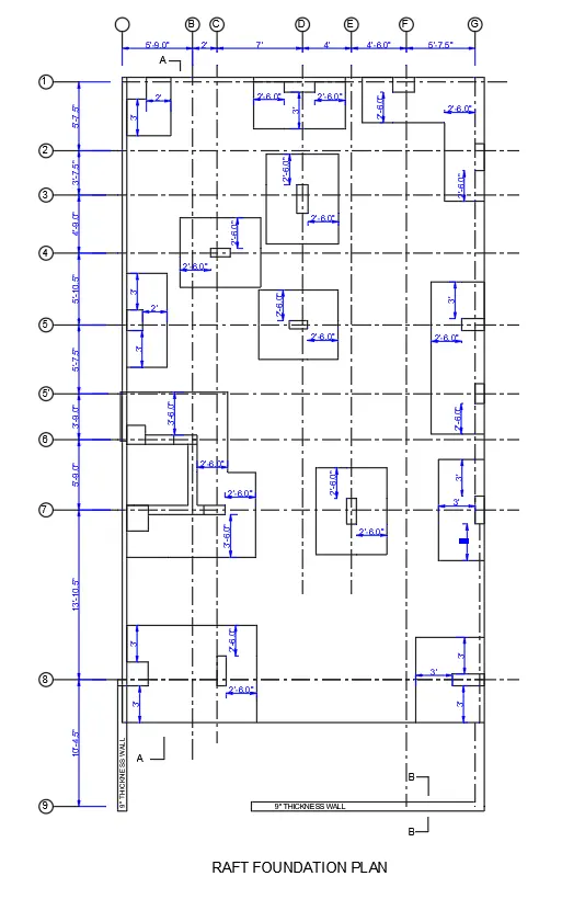
To draw the RAFT Layout using the various commands in Auto CAD.
PROCEDURE
- To create a new drawing sheet .
- Type ,,UN’ to set the units of current format of measure.(Feet and Inches)
- Type ,,LIMITS’ to set the maximum dimension limits on the particular page.
- Type ,,L’ - Line commands allows to creating a line where the end points allows creating a line where the end points are dimensional co-ordinates.
- To change the Line style was loaded from the line properties to draw the dotted line for intersection GRID Lines.
- Type ,, OFF’ – offset command to create a new object that specified distance from an existing objects or through a specified points.
- Type ,, Tr’ – Trim command is used to trims off an objects cutting the extra edges on objects.
- COPY – this commands is used to selected objects from a given square to destination, learning a copy at the originally selected location.
- TEXT – creates a text objects with specified height and orientation.
- Type ,, La ‘ to set the different layer properties of wall, door, window, slab, dimensions, text, etc.., for easily identified the different objects in the plan.
- Here we have to using the different layers properties of DIMENSIONS and TEXT.
- Finally, to save the drawing file.
RESULTS
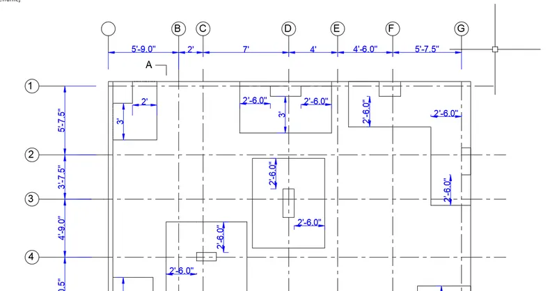
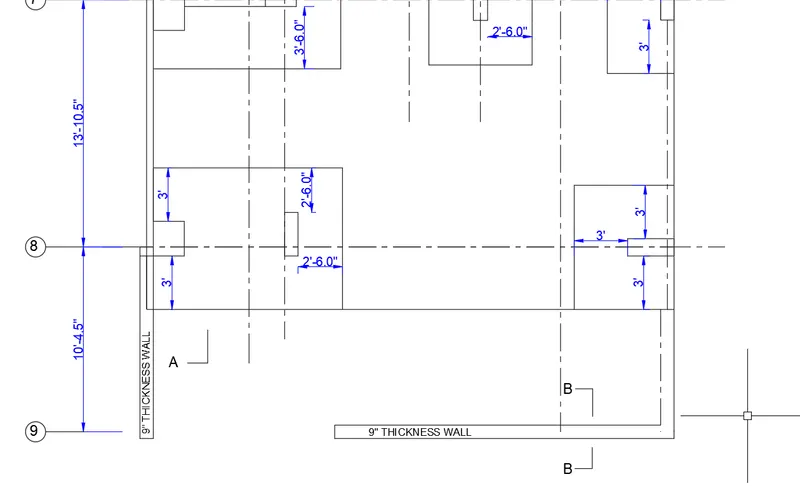
The diagram of the RAFT Layout is drawn as per dimensions using the software of Auto CAD.
DIAGRAM