Creating a Wardrobe detailed drawing, Floor Plan, Kitchen Layout and Column Detail using AutoCad
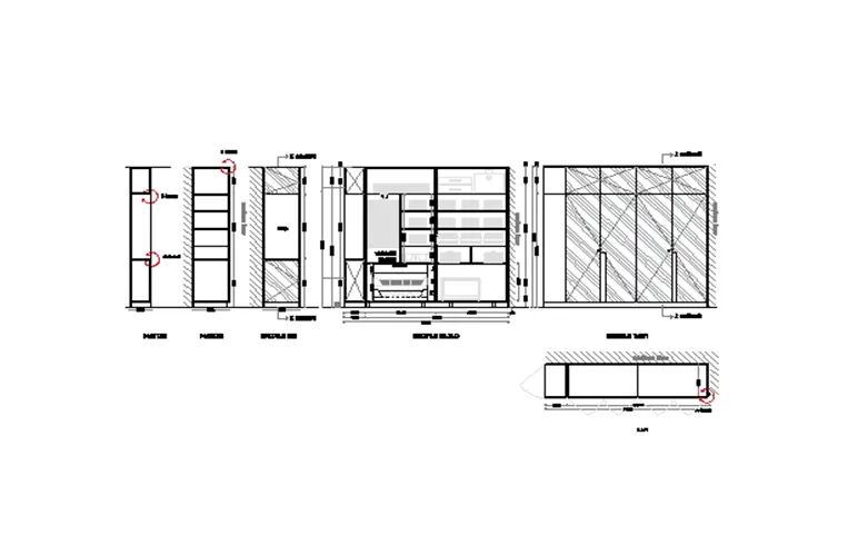
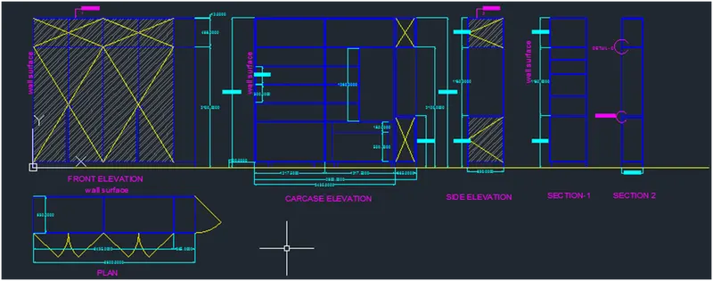
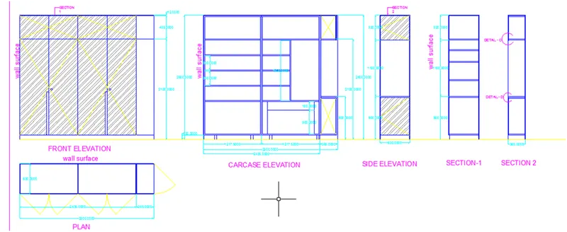
Q1.Draw the elevation and details of a wardrobe as shown in the Figure below
Ans:
Aim: To draw the elevation details of a wardrobe using AutoCAD software
Procedure:
Step 1: Basic settings
- Open AutoCAD
- Open new drawing
- Set units (measurements as decimal, precision to 0.0 , angle as decimal degree)
- Enable Ortho mode on
- Enter command dimstyle and click on modify
- Set unit to decimal and precision to 0.0
Step 2: drawing
- Use “xline” command and draw vertical and horizontal construction lines
- Use “o” command to create offset lines by providing sufficient lengths
- Use “line” tool to draw the lines at required places
- Turn on the object snap to locate mid and end points easily
- Use “trim” tool to erase the unwanted portion of lines
- Give a offset distance of “700” between elevations and sections as shown in the fig, over construction line
- Use “arc” tool to draw the swing portion of plan
Step 3: dimension
- Select dimensions tool from ribbon
- And give the all dimensions as given in diagram
Step 4: text
- Select text tool by typing text in command box
- Click the cursor at required points
- Give the text as shown in figure
- Can change the height of text by right click on the text given and properties tab
Step 5: layers
- Go to layer properties from home ribbon
- Now select new layer
- Rename it as outline and assign colour
- Do the same for diff layers and assign diff colors
- Press enter and close
- Now select the lines and assign the layers from layer panel in home ribbon
Result:
Details of a wardrobe is drawn and shown in model and layout for referrence
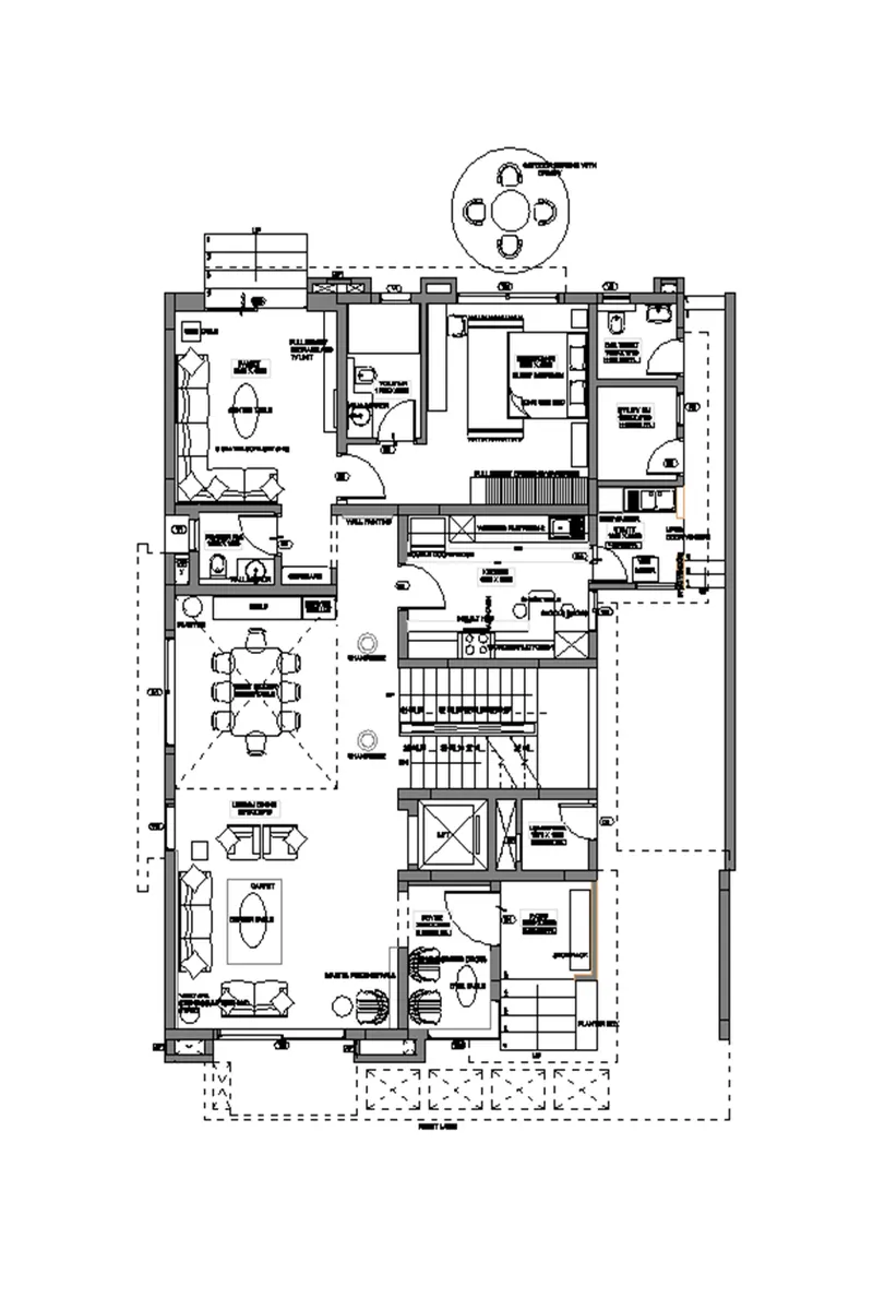
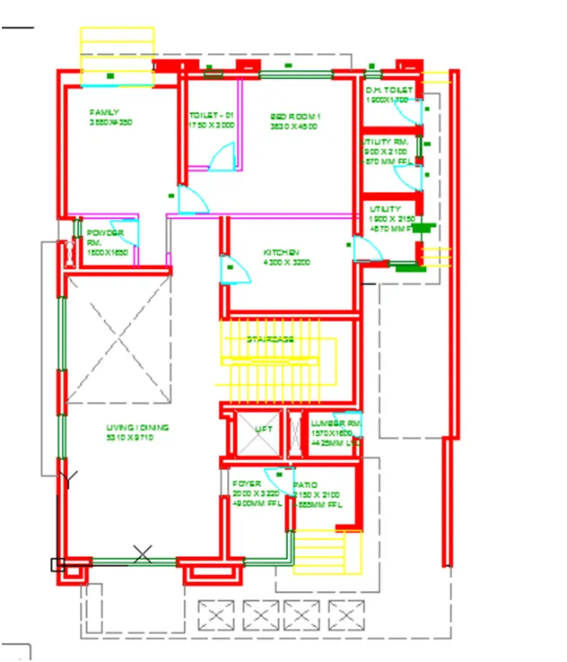
Q2.Draw the floor plan as shown in the Figure. Use the proper drafting tools to sketch the plan. Do not hatch or draw the furniture. You need to draw the floor plan with the following:
- Walls (Exterior and Interior)
- Wall Thickness: Exterior Wall- 230mm, Interior Wall: 150 mm (Wherever Required
- Doors and Windows: Assume the size of the doors and window
- Stairs: Tread-300mm, Riser-150mm
- Insert Text wherever required
- Insert the dimensions using proper dimension techniques
Aim: To draw the floor plan of a building using AutoCAD software
Procedure:
Step 1: Basic settings
- Open AutoCAD
- Open new drawing
- Set units (measurements as decimal, precision to 0.0 , angle as decimal degree)
- Enable Ortho mode on
- Enter command dimstyle and click on modify
- Set unit to decimal and precision to 0.0
Step 2: drawing
- Use “xline” command and draw vertical and horizontal construction lines
- Use “o” command to create offset lines by providing sufficient lengths
- Use “line” tool to draw the lines at required places
- Turn on the object snap to locate mid and end points easily
- Use “trim” tool to erase the unwanted portion of lines
- Use “c” in command box to create circles at any place
- Use chamfer tool and select angle and give value to provide curve edjes
- Draw doors and windows of different lengths as given in diagram
- By using different tools like (mirror , rotate , copy) create more number as required
- Use “move” tool to move the item to a particular place
Step 3: dimension
- Select dimensions tool from ribbon
- And give the all dimensions as given in diagram
Step 4: text
- Select text tool by typing text in command box
- Click the cursor at required points
- Give the text as shown in figure
- Can change the height of text by right click on the text given and properties tab
Step 5: layers
- Go to layer properties from home ribbon
- Now select new layer
- Rename it as outline and assign colour
- Do the same for diff layers and assign diff colors
- Press enter and close
- Now select the lines and assign the layers from layer panel in home ribbon
Result:
Floor plan details are drawn as per the given details and all the dimensions, etc are shown
NOTE: hatch and furniture not drawn as mentioned in the question
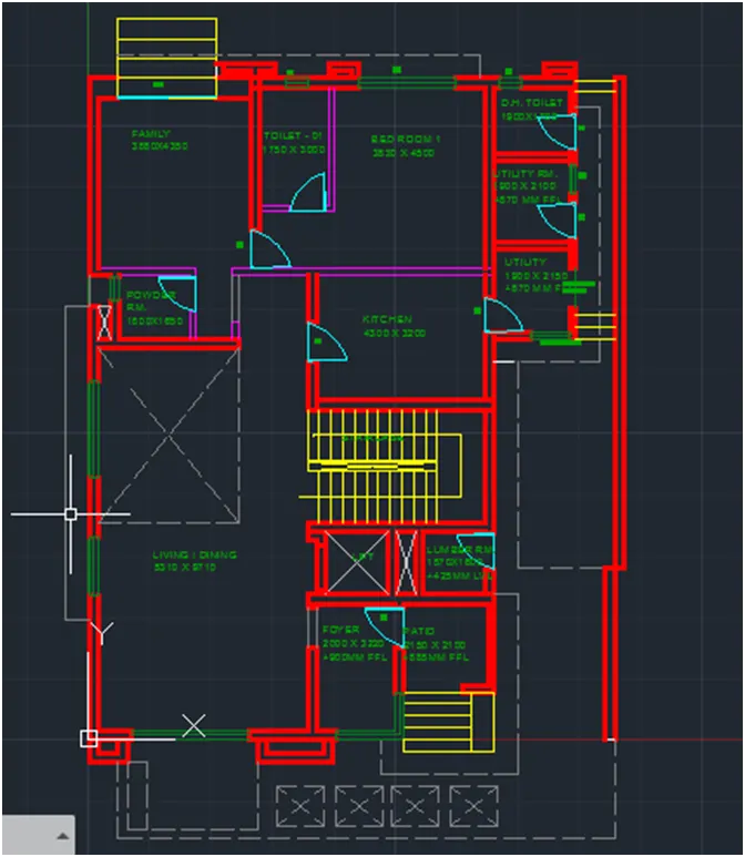
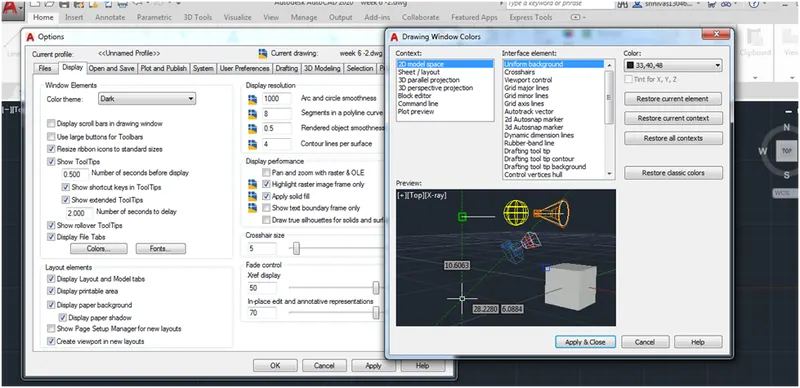
TO CHANGE THE BACKGROUND COLOUR GO TO OPTIONS AN CLICK ON DISPLAY TAB SELECT COLOURS TOOL AND THEN SELECT WHITE
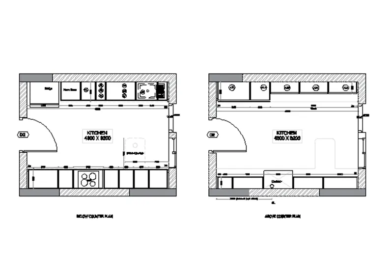
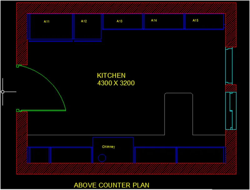
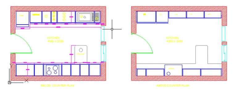
Q3. Create the Kitchen Layout as shown in the Figure below. Also, use proper dimension techniques to dimension the kitchen layout. Also, insert text wherever required. All dimensions are in mm.
Ans:
Aim: To draw the kitchen layout using AutoCAD software
Procedure:
Step 1: Basic settings
- Open AutoCAD
- Open new drawing
- Set units (measurements as decimal, precision to 0.0 , angle as decimal degree)
- Enable Ortho mode on
- Enter command dimstyle and click on modify
- Set unit to decimal and precision to 0.0
Step 2: drawing
- select line tool and select a start point
- move the cursor right side and give a length of 4230
- now move the cursor up wards and give a length of 3200
- move the cursor left side and give a length of 4230
- now enter “c” to close the rectangle
- select “offset” tool and give a length of 230
- now give offset for the 4 lines in the rectangle to outside by cursor click
- now add door and windows as given in the drawing
- now use copy tool and produce same drawing by the side of the original drawing
- by using “line , offset, trim, circle ”tools draw the furniture in 2 drawings as given in the diagram
Step 3: dimension
- Select dimensions tool from ribbon
- And give the all dimensions as given in diagram
- Use “dimcontinue” command to give the continuous dimensions for the furniture as given in the drawing
Step 4: text
- Select text tool by typing text in command box
- Click the cursor at required points
- Give the text as shown in figure
- Can change the height of text by right click on the text given and properties tab
Step 5: layers
- Go to layer properties from home ribbon
- Now select new layer
- Rename it as wall and assign color
- Do the same for diff layers and assign diff colors
- Press enter and close
- Now select the lines and assign the layers from layer panel in home ribbon
Result:
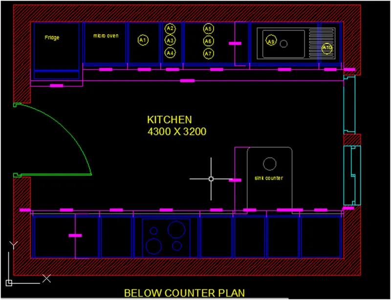
- Kitchen details are drawn as per the given details and all the furniture , dimensions, etc are shown
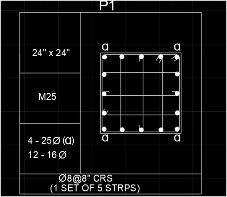
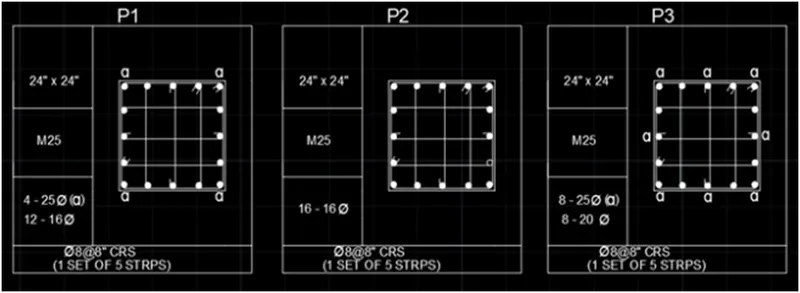
Q4. Sketch the column details as shown in Figure. Insert dimensions and text in the figure. Refer to the bar sizes from the schedule.
8mm ---- 0.31 Inches
25mm--- 1 inches
16mm—0.62 inches
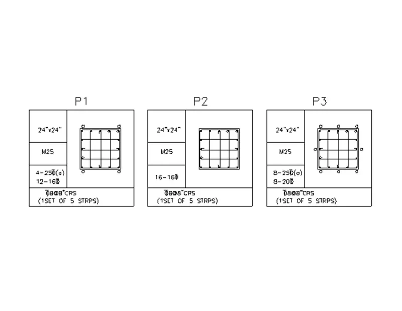
Aim: To prepare the column schedule as given in the drawing using Auto CAD
Procedure:
Step 1: Basic settings
- Open AutoCAD
- Open new drawing
- Set units (measurements as engineering, precision to 0’-0.0” , angle as decimal degree)
- Enable Ortho mode on
- Enter command dimstyle and click on modify
- Set unit to engineering and precision to 0’-0.0”
Step 2: Creating table:
- Select line tool and locate a start point
- Move the cursor right side and give a length of 4’
- Move the cursor downward and give a length of 4’
- Move the cursor left side and give a length of 4’
- Now enter “c” in the command box to close the box
- Select the “offset” tool and give a length of 3’
- Select the right vertical line and move the cursor left side and press enter
- Select the “offset” tool and give a length of 1’
- Select the top line and move the cursor down ward and press enter for 3 circuits
- Now select “trim” tool and delete the unwanted lines as given
- Select “copy” tool and copy the whole drawing and paste it side by side 2 times to form 3 tables as given in the drawing
Step 3: Text
- Select text tool by typing text in command box
- Click the cursor at required points
- Give the text as shown in figure
- Can change the height of text by right click on the text given and properties tab
Step 4: Drawing the column section:
- Draw a rectangle using rectangle tool and give dimensions as 24” and 24”
- Select offset tool and give a offset length of 1” and produce inside offset of rectangle using cursor
- Select circle tool
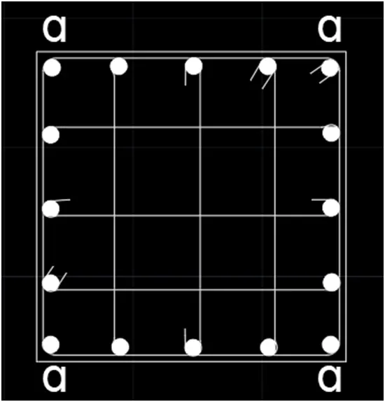
- Start at a point and give a dia of 1” (25mm)
- Select move tool and move the circle to the top left corner of the inside rectangle
- Select copy tool and select the circle and move it to the all the corners
- Select division tool and divide the inside line into 4 parts
- Then type “DDPTYPE” in command box and give visible style for points
- Select circle tool
- Start at a point and give a dia of 0.62” (16mm)
- Select copy tool and select the circle and move it to the all the dot positions as given
- Select hatch tool then select solid and give solid to all the circles
- Select line tool and and connect the circles as shown in the fig to form stirrups
- Select arc and give at the hook position as given
- Now select all the drawing and give “join” command
- Follow the same procedure for all the other columns with their respective size and diameter of reinforcement
- Now select the columns and use move tool to place the columns in the table
Result:
Column details are drawn as per the given details and all the dimensions, etc are shown as given in the drawing
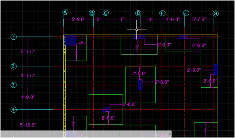
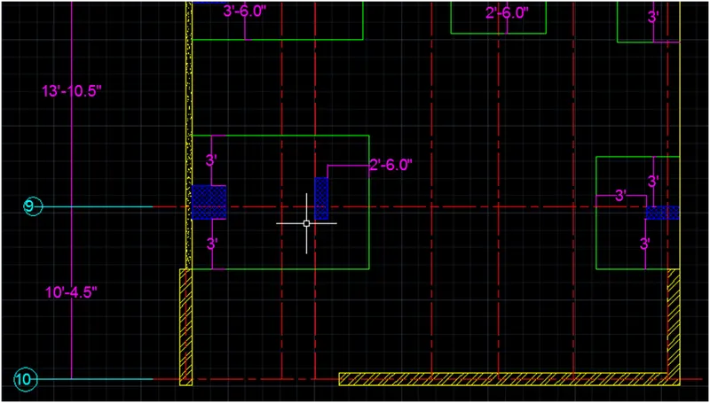
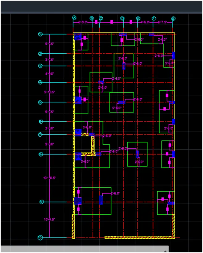
Q 5. Draw the Raft Layout as shown in the Figure. Assume the column size as per your knowledge. You can take the sizes as: 24”x24”, 9” x 24”, 9” x 18”, and 9’ x 24”. You can import the raft_foundation.pdf to ensure the missing dimensions.
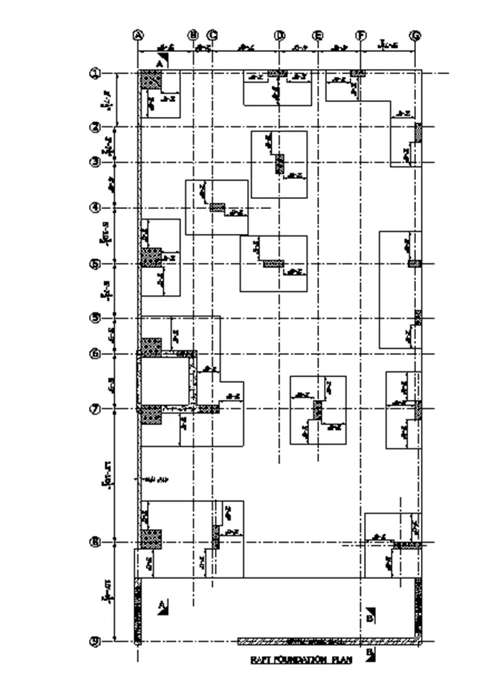
Aim: To draw the raft layout and give the all necessary dimensions as given in the diagram using Auto CAD
Procedure:
Step 1: Basic settings
- Open AutoCAD
- Open new drawing
- Set units (measurements as engineering, precision to 0’-0.0” , angle as decimal degree)
- Enable Ortho mode on
- Enter command dimstyle and click on modify
- Set unit to engineering and precision to 0’-0.0”
Step 2: drawing
- Use “xline” command and draw vertical and horizontal construction lines
- Use “o” command to create offset lines by providing sufficient lengths
- Use “line” tool to draw the lines at required places
- Turn on the object snap to locate mid and end points easily
- Use “trim” tool to erase the unwanted portion of lines
- Use “c” in command box to create circles at any place
- By using different tools like (mirror , rotate , copy) create more number as required
- Use “move” tool to move the item to a particular place
Step 3: dimension
- Select dimensions tool from ribbon
- And give the all dimensions as given in diagram
Step 4: text
- Select text tool by typing text in command box
- Click the cursor at required points
- Give the text as shown in figure
- Can change the height of text by right click on the text given and properties tab
Step 5: layers
- Go to layer properties from home ribbon
- Now select new layer
- Rename it as outline and assign colour
- Do the same for diff layers and assign diff colors
- Press enter and close
- Now select the lines and assign the layers from layer panel in home ribbon
Result:
Raft details are drawn as per the given details and all the dimensions, etc are shown