Creating a Wardrobe detailed drawing, Floor Plan, Kitchen Layout and Column Detail using AutoCad
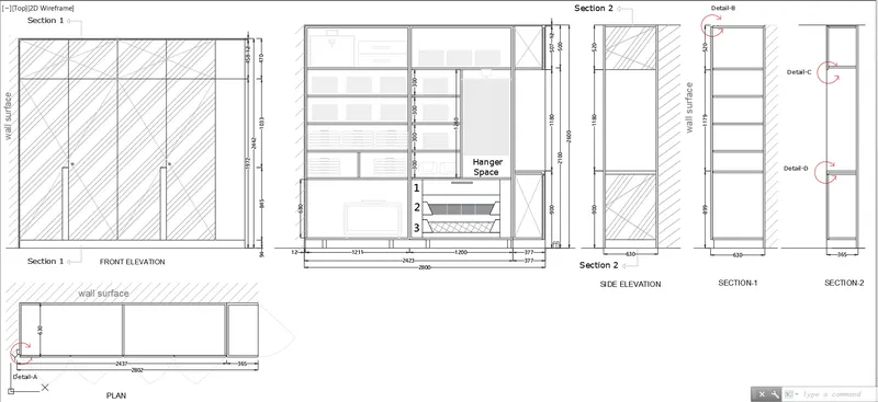
Aim: - To draw the elevation and details of a wardrobe as shown in the figure above using AutoCAD.
Introduction: - A wardrobe is a standing closet used for storing clothes. The Wardrobe detailed drawing is created in AutoCAD using primarily the Line tool and after sketching, the dimensions and text are provided with the use of layers. The procedure of drawing is explained in detail with diagrams of each step and the final result is given.
PROCEDURE: -
Before we start the drawings we need to set up the drawing as Metric and the units into Decimal Units.
Following are the steps in order to set up the drawing as Imperial Template and the units into Engineering Units.
- Go to Application Menu or click CTRL + N (New)
- Click on New from the Application Menu
- A popup menu appears, click on the first tab known as Start from Scratch > Select Metric
- Now click on the third tab known as Use a Wizard > Go to Advance setup > A Dialog box appears > Select the unit of measurement as Decimal > Press Next > select Angle as Decimal Degrees > Press Next > Select Angle Measure > Press Next > Select Angle Direction > Press Next > Select Area > Click Finish
- Set the page limit by entering Limits in the command tab. The lower left corner is specified as 0,0 and the upper right corner is specified as 410, 297.
- In the Drawing Units dialog box, select 'Engineering' in Type; ' 0 ' in Precision; and 'Millimeter' in Insertion scale.
- Click OK
- Now we are all set to go.
Now,
- Import the drawing pdf which we are given to draw.
- Go to Ribbon Tab
- Click on Insert
- Then click on the PDF Import tool
- Import the required pdf.
Now,
- In order draw the drawing perfectly according to the size, we need to Scale it.
- So draw any dimension of the imported drawing like the size of the section wardrobe and draw it on the workspace by using line tool and direct distance method.
In order to Scale the Drawing,
- First select the entire imported drawing
- Select the base point
- Go to Reference option in the command box
- Select any dimension length of the imported drawing
- Then directing enter the scale length like 2800 or
- You can click on Points in the command box and select the two points of the line i.e., the first and the end point of the line which you have drawn.
- Now you are all set to go.
Now,
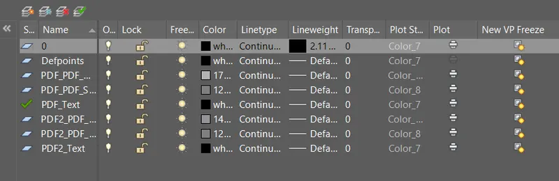
- Type LA or Layer command in the command box.
- A layer dialog box appears
- Choose the required layers.
Now,
Type "L" or Line in the command box.
- Specify first corner point by clicking anywhere in the workspace.
- Using direct distance method, move the cursor and draw line of length 2800.
- Specify the next point in y direction of length 2600.
- Specify the next point in y direction of length 2800.
- Close the box by clicking on Close in the command box.
Now,
Type 'o' or offset in the command box.
- Specify offset distance of 12 and press enter.
- Select the required lines to offset.
- Select the lines which drawn earlier and offset it.
- Press Escape to exit the command.
Again,
Type 'o' or offset in the command box.
- Specify offset distance of 1223 and press enter.
- Select the required lines to offset.
- Select the lines which drawn earlier and offset it.
- Press Escape to exit the command.
Again,
Type 'o' or offset in the command box.
- Specify offset distance of 1200 and press enter.
- Select the required lines to offset.
- Select the lines which drawn earlier and offset it.
- Press Escape to exit the command.
Again,
Type 'o' or offset in the command box.
- Specify offset distance of 100 and press enter.
- Select the required lines to offset.
- Select the lines which drawn earlier and offset it.
- Press Escape to exit the command.
Again,
Type 'o' or offset in the command box.
- Specify offset distance of 488 and press enter.
- Select the required lines to offset.
- Select the lines which drawn earlier and offset it.
- Press Escape to exit the command.
Again,
Type 'o' or offset in the command box.
- Specify offset distance of 20 and press enter.
- Select the required lines to offset.
- Select the lines which drawn earlier and offset it.
- Press Escape to exit the command.
- Type 'T' or Trim and select Edge No Extend
- Trim off the extra portion.
Again,
Type 'o' or offset in the command box.
- Specify offset distance of 680 and press enter.
- Select the required lines to offset.
- Select the lines which drawn earlier and offset it.
- Press Escape to exit the command.
Again,
Type 'o' or offset in the command box.
- Specify offset distance of 320 and press enter.
- Select the required lines to offset and offset 3 times.
- Press Escape to exit the command.
Again,
Type 'o' or offset in the command box.
- Specify offset distance of 2 and press enter.
- Select the required lines to offset and offset 4 times at bottom.
- Press Escape to exit the command.
Again,
Type 'o' or offset in the command box.
- Specify offset distance of 900 and enter
- Select the object to offset and select bottom edge & click on top
- Type 'T' or Trim and select Edge No Extend
- Trim off the extra portion.
Again,
Type 'o' or offset in the command box.
- Specify offset distance of 1180 and press enter
- Select object to offset select the last offset line& click at the top
- Create thickness offset 2 on both sides
- Using line command drew cross line
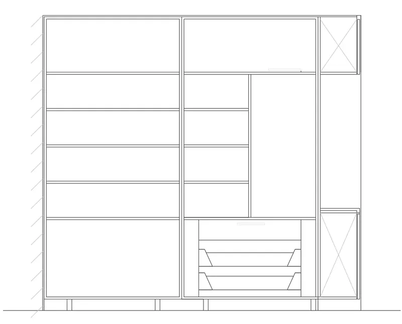
Now,
- Let us draw the the various components inside the wardrobe as shown the figure.
- For this select the particular layer pdf_pdf_geometry for the various components and object colour as 223,223,223.
- Draw the various components using the various tools like OFFSET, ARRAY, RECTANGLE etc.
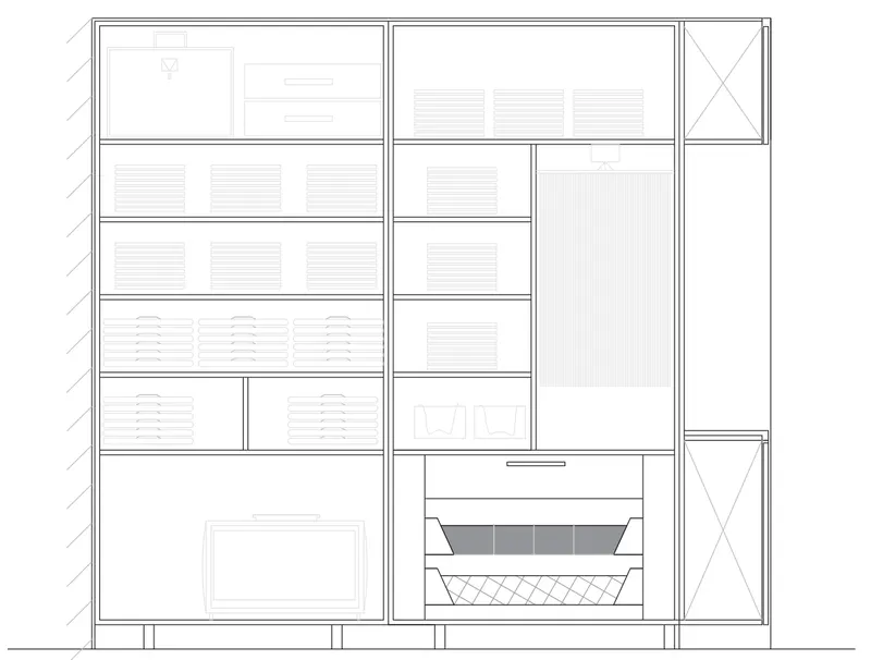
Similarly, the Sections, Elevations and Plan are also drawn in the same way.
Now, its time for Dimension.
- Select the Layer pdf_text for the various dimension.
- Type 'D' or Dimension Style
- Select the size of the arrow as 40 and text height as 45.
- Select the arrow as Open Arrow.
RESULT: -
---------------------------------------------------------X-----------------------------------------------------------------------
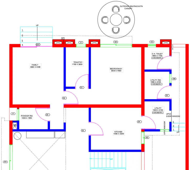
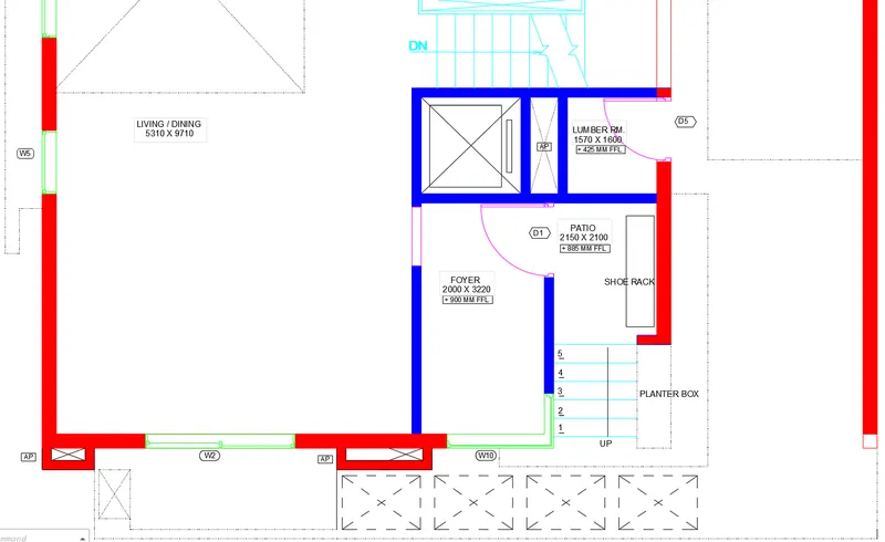
Aim: - To draw the floor plan as shown in the figure above using AutoCAD.
Introduction: - The floor plan is drawn using proper drafting tools, primarily using the Line tool and after sketching, the dimensions and text are provided with the use of layers. The procedure of drawing is explained in detail with diagrams of each step and the final result is given.
All dimensions are taken in mm.
- Exterior Wall Thickness is taken as 230 mm.
- Interior Wall Thickness is taken as 150 mm.
- In stair case, size of tread is taken as 300 mm.
- And size of riser is taken as 150 mm.
- The doors and windows are assumed as per the requirement.
PROCEDURE: -
Before we start the drawings we need to set up the drawing as Metric and the units into Decimal Units.
Following are the steps in order to set up the drawing as Imperial Template and the units into Engineering Units.
- Go to Application Menu or click CTRL + N (New)
- Click on New from the Application Menu
- A popup menu appears, click on the first tab known as Start from Scratch > Select Metric
- Now click on the third tab known as Use a Wizard > Go to Advance setup > A Dialog box appears > Select the unit of measurement as Decimal > Press Next > select Angle as Decimal Degrees > Press Next > Select Angle Measure > Press Next > Select Angle Direction > Press Next > Select Area > Click Finish
- Set the page limit by entering Limits in the command tab. The lower left corner is specified as 0,0 and the upper right corner is specified as 410, 297.
- In the Drawing Units dialog box, select 'Engineering' in Type; ' 0 ' in Precision; and 'Millimeter' in Insertion scale.
- Click OK
- Now we are all set to go.
Now,
- Import the drawing pdf which we are given to draw.
- Go to Ribbon Tab
- Click on Insert
- Then click on the PDF Import tool
- Import the required pdf.
Now,
- In order draw the drawing perfectly according to the size, we need to Scale it.
- So draw any dimension of the imported drawing like the size of the section wardrobe and draw it on the workspace by using line tool and direct distance method.
In order to Scale the Drawing,
- First select the entire imported drawing
- Select the base point
- Go to Reference option in the command box
- Select any dimension length of the imported drawing
- Then directing enter the scale length like 3880 or
- You can click on Points in the command box and select the two points of the line i.e., the first and the end point of the line which you have drawn.
- Now you are all set to go.
Now,
- Type LA or Layer command in the command box.
- A layer dialog box appears
- Choose the required layers.
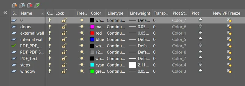
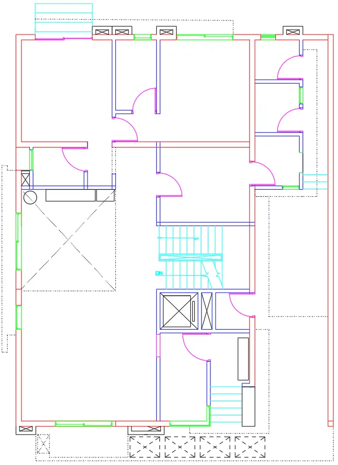
Now, draw the external as well as the internal walls
Type "L" or Line in the command box.
- Specify first corner point by clicking anywhere in the workspace.
- Using direct distance method, move the cursor and draw line of length 13572.
- Specify the next point in y direction of length 16721.
- Specify the next point in x direction of length 13572.
- Close the box by clicking on Close in the command box.
- Press Escape or Esc to close the command.
- Now draw the external and internal wall.
- Also draw the different doors, windows ventilators, etc.
-
The size of windows and doors are assumed as:
Door 1 or D1: 1200mm x 2200 mm
D2: 1000mm x 2100mm
D3: 900mm x 2100mm
D4: 800mm x 2100mm
D5: 700mm x 2100mm
Slide Door: 2300mm x 2100mm
W1: 2500mm x 1500mm
W2: 2300mm x 1500mm
W3: 1000mm x 1500mm
W5: 1100mm x 1500mm
W9: 900mm x 1500mm
Window 10 is a box glass opening
V1: 800mm x 500mm
V2: 700mm x 500mm
Now,
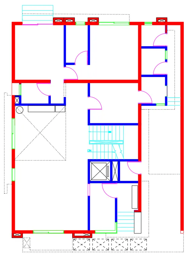
- Do the Hatching.
- Go to draw panel.
- Select Hatch and select Solid hatching.
- For external wall, select the red solid colour as per the external wall layer colour.
- For internal wall, select the red solid colour as per the external wall layer colour.
Now, it's time for Dimension.
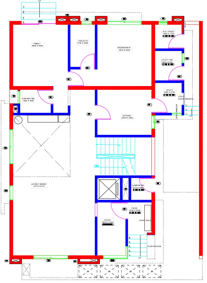
- Select the Layer pdf_text for the various dimension.
- Type 'D' or Dimension Style
- Select the size of the text height as 98.
- For the dashed line, go to the above of properties panel.
- Select ACAP_ISO03W100
RESULT: -
----------------------------------------------------------X-----------------------------------------------------------------------------
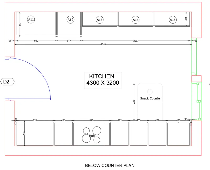
Aim: - To create the Kitchen Layout as shown in the figure using AutoCAD.
Introduction: - The Kitchen Layout is drawn using proper drafting tools, primarily using the Line tool and after sketching, the dimensions and text are provided with the use of layers. The procedure of drawing is explained in detail with diagrams of each step and the final result is given.
All dimensions are taken in mm.
PROCEDURE: -
Before we start the drawings we need to set up the drawing as Metric and the units into Decimal Units.
Following are the steps in order to set up the drawing as Imperial Template and the units into Engineering Units.
- Go to Application Menu or click CTRL + N (New)
- Click on New from the Application Menu
- A popup menu appears, click on the first tab known as Start from Scratch > Select Metric
- Now click on the third tab known as Use a Wizard > Go to Advance setup > A Dialog box appears > Select the unit of measurement as Decimal > Press Next > select Angle as Decimal Degrees > Press Next > Select Angle Measure > Press Next > Select Angle Direction > Press Next > Select Area > Click Finish
- Set the page limit by entering Limits in the command tab. The lower left corner is specified as 0,0 and the upper right corner is specified as 410, 297.
- In the Drawing Units dialog box, select 'Engineering' in Type; ' 0 ' in Precision; and 'Millimeter' in Insertion scale.
- Click OK
- Now we are all set to go.
Now,
- Import the drawing pdf which we are given to draw.
- Go to Ribbon Tab
- Click on Insert
- Then click on the PDF Import tool
- Import the required pdf.
Now,
- In order draw the drawing perfectly according to the size, we need to Scale it.
- So draw any dimension of the imported drawing like the size of the section wardrobe and draw it on the workspace by using line tool and direct distance method.
In order to Scale the Drawing,
- First select the entire imported drawing
- Select the base point
- Go to Reference option in the command box
- Select any dimension length of the imported drawing
- Then directing enter the scale length like 4230 or
- You can click on Points in the command box and select the two points of the line i.e., the first and the end point of the line which you have drawn.
- Now you are all set to go.
Now,
- Type LA or Layer command in the command box.
- A layer dialog box appears
- Choose the required layers as per the Kitchen Layout.
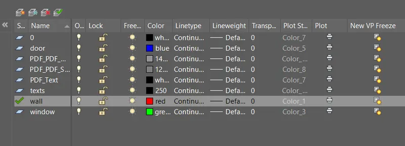
Now,
- Select the wall layer and draw the walls
- Take offset of 230 mm.
- Trim the unwanted lines.

Now,
- Draw the doors and windows
- Use the respective layers
- Taking door size as 1050 X 2100
- And Window size as 930 X 1200
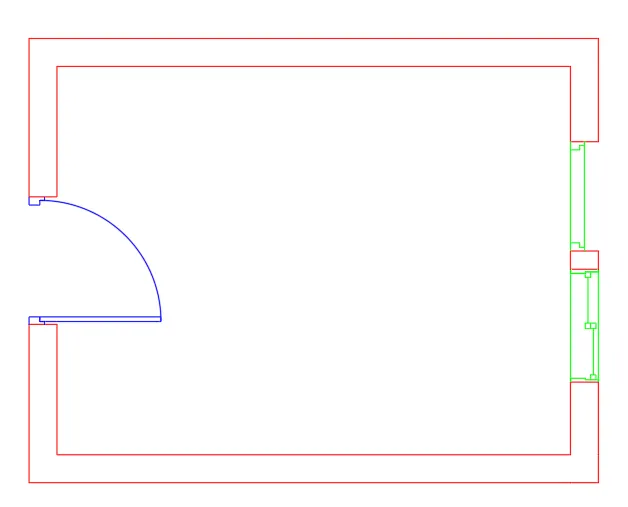
Now,
- Draw the other components of the Kitchen.
- Use the different drafting tools like offset, trim, etc.
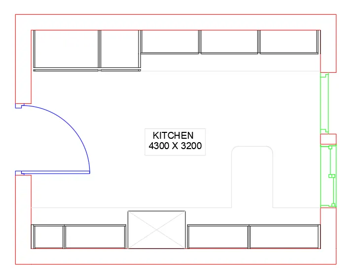
Now, its time for Dimension
- Enter 'DST command in the command tab to open the Dimension Style Manager dialog box.
- Click on Standard
- Click on the Modify tab.
- Select the arrow size as 40 and the text size as 45
- Select text colour as yellow
- Type Dimlinear in the command box for linear dimensions
- Type Dimaligned in the command box for aligned dimensions
- Type Dimangular in the command box for angular dimensions
- Rest leave everything as it is.
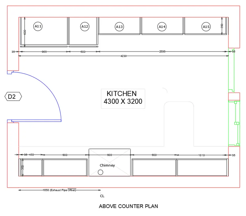
Note: - The same steps are followed for the second drawing too.
RESULT: -
--------------------------------------------------------X----------------------------------------------------------------------------
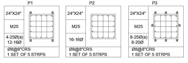
Aim: - To Sketch the column details as shown in Figure using AutoCAD.
Introduction: - The column details is drawn using proper drafting tools, primarily using the Line tool and after sketching, the dimensions and text are provided with the use of layers. The procedure of drawing is explained in detail with diagrams of each step and the final result is given.
All dimensions are taken inches.
PROCEDURE: -
Before we start the drawings we need to set up the drawing as Imperial and the units into Engineering Units.
Following are the steps in order to set up the drawing as Imperial Template and the units into Engineering Units.
- Go to Application Menu or click CTRL + N (New)
- Click on New from the Application Menu
- A popup menu appears, click on the first tab known as Start from Scratch > Select Imperial
- Now click on the third tab known as Use a Wizard > Go to Advance setup > A Dialog box appears > Select the unit of measurement as Engineering > Press Next > select Angle as Decimal Degrees > Press Next > Select Angle Measure > Press Next > Select Angle Direction > Press Next > Select Area > Click Finish
- Set the page limit by entering Limits in the command tab. The lower left corner is specified as 0',0' and the upper right corner is specified as 100', 100'.
- In the Drawing Units dialog box, select 'Engineering' in Type; ' 0',0" ' in Precision; and 'Inches' in Insertion scale.
- Click OK
- Now we are all set to go.
Now,
- Import the drawing pdf which we are given to draw.
- Go to Ribbon Tab
- Click on Insert
- Then click on the PDF Import tool
- Import the required pdf.
Now,
- In order draw the drawing perfectly according to the size, we need to Scale it.
- So draw any dimension of the imported drawing like the size of the section wardrobe and draw it on the workspace by using line tool and direct distance method.
In order to Scale the Drawing,
- First select the entire imported drawing
- Select the base point
- Go to Reference option in the command box
- Select any dimension length of the imported drawing
- Then directing enter the scale length like 4230 or
- You can click on Points in the command box and select the two points of the line i.e., the first and the end point of the line which you have drawn.
- Now you are all set to go.
Now,
- Let us draw the 24"X24" column size.
- Type L or line command and specify the first point anywhere in th eworking space
- Specify the next point @24" by using direct distance method.
So we get the following drawing,
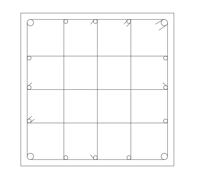
Now,
- Draw the outer boundaries
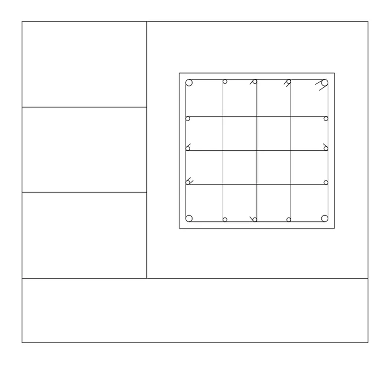
Now,
- Give the texts asper the drawing given.
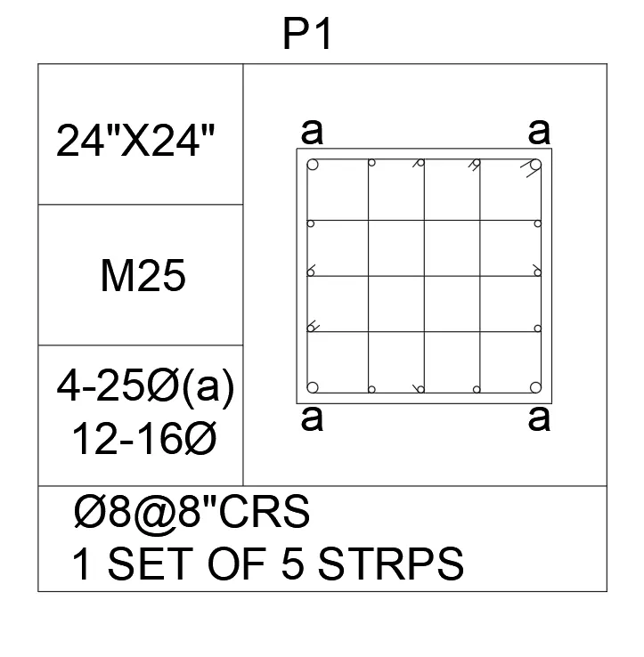
Note: - Similarly, we can draw the the other two drawings following the same steps as above.
RESULT: -
--------------------------------------------------------------------------------------------------x----------------------------------------------------------
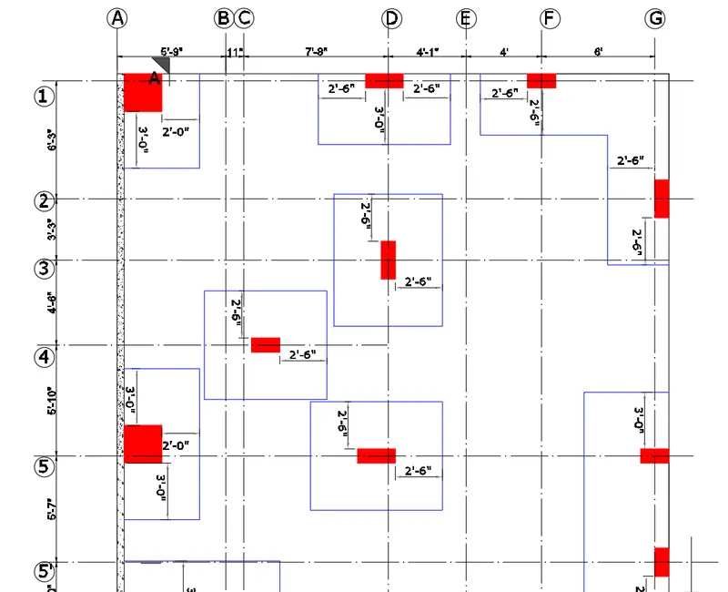
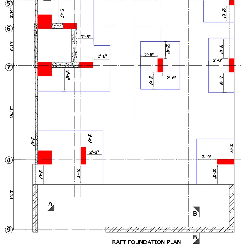
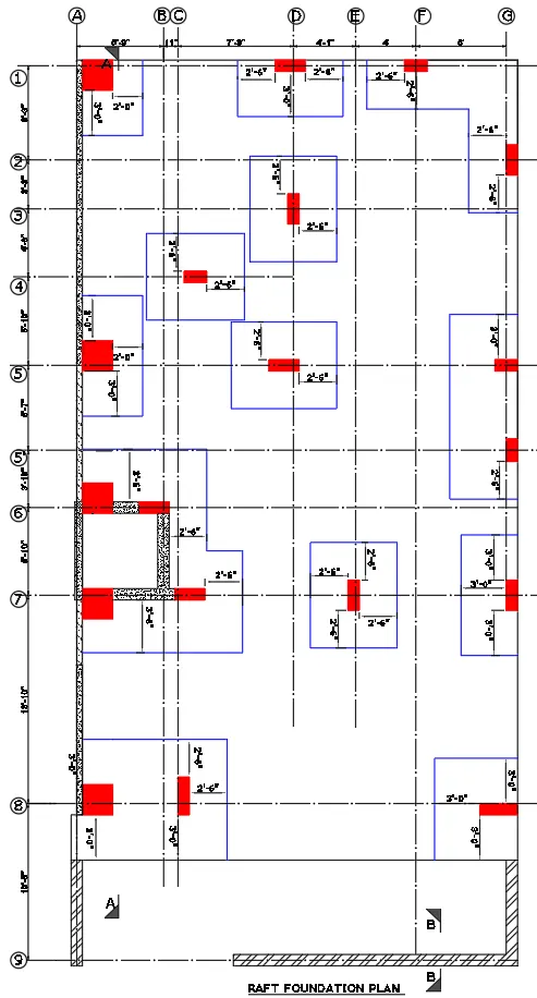
Aim: - To Sketch the column details as shown in Figure using AutoCAD.
Introduction: - The column details is drawn using proper drafting tools, primarily using the Line tool and after sketching, the dimensions and text are provided with the use of layers. The procedure of drawing is explained in detail with diagrams of each step and the final result is given.
All dimensions are taken inches.
PROCEDURE: -
Before we start the drawings we need to set up the drawing as Imperial and the units into Engineering Units.
Following are the steps in order to set up the drawing as Imperial Template and the units into Engineering Units.
- Go to Application Menu or click CTRL + N (New)
- Click on New from the Application Menu
- A popup menu appears, click on the first tab known as Start from Scratch > Select Imperial
- Now click on the third tab known as Use a Wizard > Go to Advance setup > A Dialog box appears > Select the unit of measurement as Engineering > Press Next > select Angle as Decimal Degrees > Press Next > Select Angle Measure > Press Next > Select Angle Direction > Press Next > Select Area > Click Finish
- Set the page limit by entering Limits in the command tab. The lower left corner is specified as 0',0' and the upper right corner is specified as 100', 100'.
- In the Drawing Units dialog box, select 'Engineering' in Type; ' 0',0" ' in Precision; and 'Inches' in Insertion scale.
- Click OK
- Now we are all set to go.
Now,
- Import the drawing pdf which we are given to draw.
- Go to Ribbon Tab
- Click on Insert
- Then click on the PDF Import tool
- Import the required pdf.
Now,
- In order draw the drawing perfectly according to the size, we need to Scale it.
- So draw any dimension of the imported drawing like the size of the section wardrobe and draw it on the workspace by using line tool and direct distance method.
In order to Scale the Drawing,
- First select the entire imported drawing
- Select the base point
- Go to Reference option in the command box
- Select any dimension length of the imported drawing
- Then directing enter the scale length like 4230 or
- You can click on Points in the command box and select the two points of the line i.e., the first and the end point of the line which you have drawn.
- Now you are all set to go.
Now,
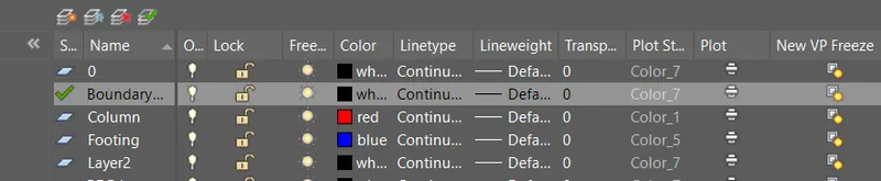
- Type LA or Layer command in the command box.
- A layer dialog box appears
- Choose the required layers as per the Raft footing.
Now,
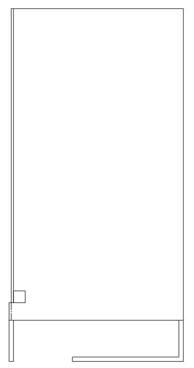
- Let us draw the boundary wall and the nine inches thick wall.
Now,
- We draw the various columns assuming their sizes as per requirement and the raft.
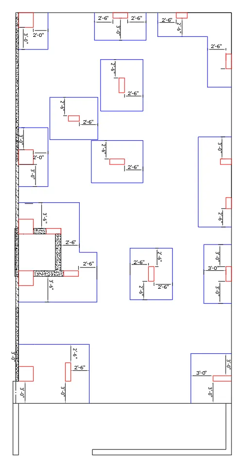
Now,
- We provide the various hatches as per the drawing.
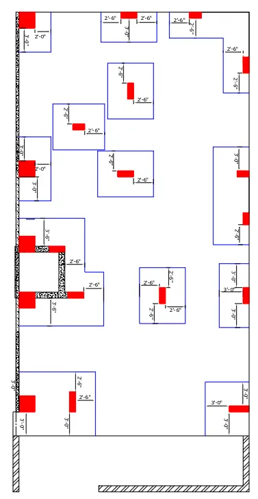
Now,
- We provide the centered lines as per the drawing.
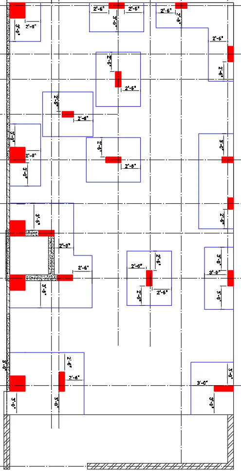
Now, its time for Dimension
- Enter 'DST command in the command tab to open the Dimension Style Manager dialog box.
- Click on Standard
- Click on the Modify tab.
- Select the arrow size as 3" and the text size as 5"
- Select text colour as yellow
- Type Dimlinear in the command box for linear dimensions
- Type Dimaligned in the command box for aligned dimensions
- Type Dimangular in the command box for angular dimensions
- Rest leave everything as it is.
RESULT: -
We have the following result,