Creating a Wardrobe detailed drawing, Floor Plan, Kitchen Layout and Column Detail using AutoCad
Aim:
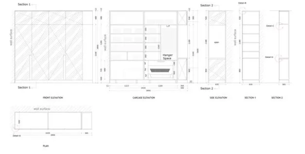
To draw the elevations and deatails of wardrobe as shown in figure
introduction: AutoCAD consists of a number of drawing and modification tools. Among the modification toolss are
chamfer,fillet,offset,object snap, rotate,copy.move,mirror,trim,entend and join Chamfer. A chamfer is an angled line that meets the endpoints of two straight 2D objects its a sloped transition between two surfaces or adjacent faces on a 3D solid. We type CHA for this tool in command bar
drafting a following tools by using following commands like, by using object snap elliptical command, by using arcs commands construction lines and ray tools, divide and measure tool, and by Using modity commands like mirror, trim, entand explode, lenghten, align, break and join command, and manage layers in autoCAD 2019
Fillet: The fillet command is used to create rounded edges between the adjacent lines and faces in 2D and 3D. It is also used to connect two tangent arcs in 2D.Type F
Offest: Creates concentric circles, parallel lines,
and parallel curves.Type O in the command bar
Object Snap: Object snaps provide a way to specify precise locations on objects whenever we are prompted for a point within a command.Type OS in the command bar
Rotate: Rotates objects around a base point. Wcan rotate selected objects around a base point to an absolute angle. We type RO and rotate the object accordingly
Copy: Copies objects a specified distance in a specified
direction.We can enter C in the command line
Move: Moves objects a specified distance in a
specified direction.Type M in the command bar
Mirror: Creates a mirrored copy of selected objects. Wcan create objects that represent half of a drawing, select them, and mirror them across a specified line to create the other half. Type MI in the command bar
Trim: Trims objects to meet the edges of other objects.
Type TR in the command bar.
Extent: Extends objects to meet the edges of other objects.It extend objects, first select the boundaries. Then press Enter and select the objects that you want to extend. To use all objects as boundaries, press Enter at the first Select Objects prompt
Join: Joins the endpoints of linear and curved objects to create a single object, it combines a series of finite linear and open curved objects .
Start by typing ONEW in the command box
• Advanced Setup > Set the Units, Angle, Angle measure, Angle direction and area.
After settings provide the lower limit and upper limit.
Now we can start the sketching.
Commands used:
1. XL-V OR XL-H.
2. Offset.
3. Fillet.
4. Extend
5. Trim.
Procedure:
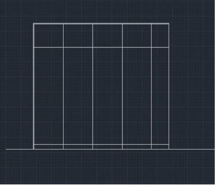
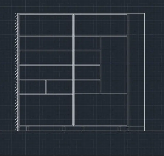
Draw the rectangle of size 2800 X 2600, then offset it with
12 and 488 mm from upper side.
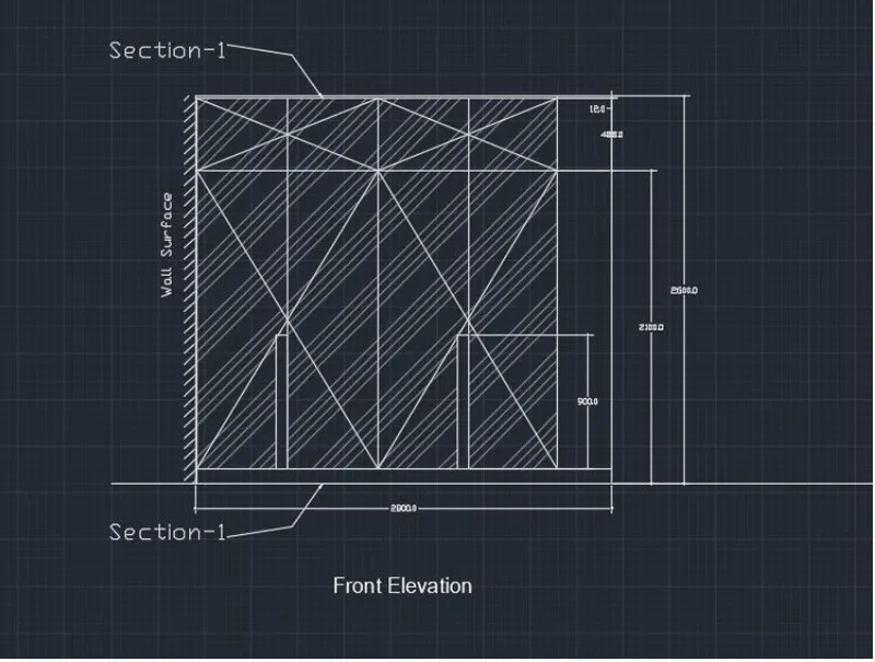
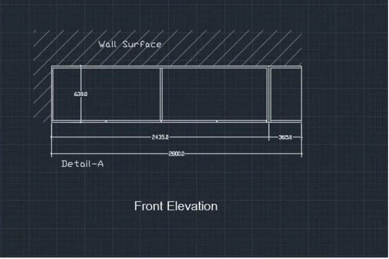
For Front elevation use line command and offset
command as per the dimension. After making the wardrobe box, use hatch command and do dimension a per drawing.
In the command line thpe Qleader to annotate the section 1
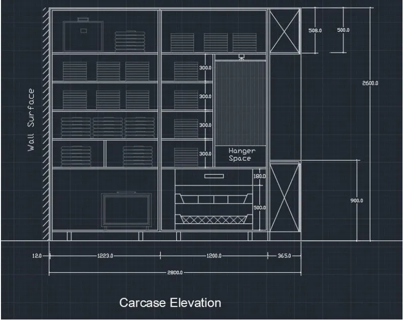
For Carcase Elevation, Make rectangle of size 2800 X2600.
And offset it as per the front elevation size.
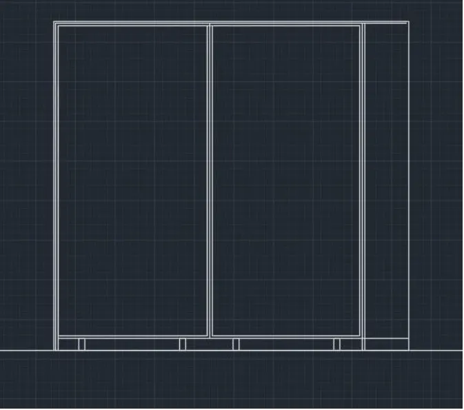
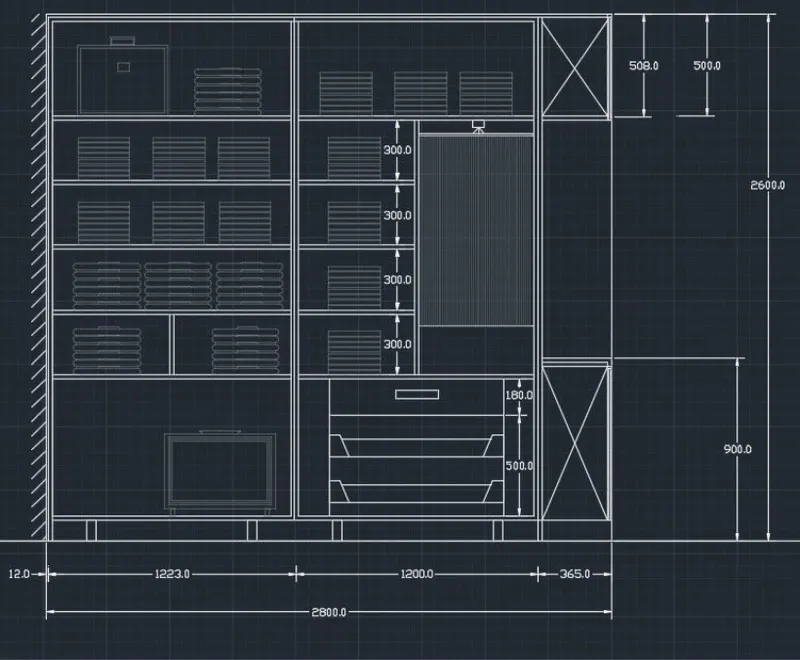
After this, draw the different cabinets in the wardrobe using line and offset command as per drawing.
Draw different components like television and books,
24%
briefcase and More.
Do dimmesioning as per the drawing.
Place the text as per the drawing.
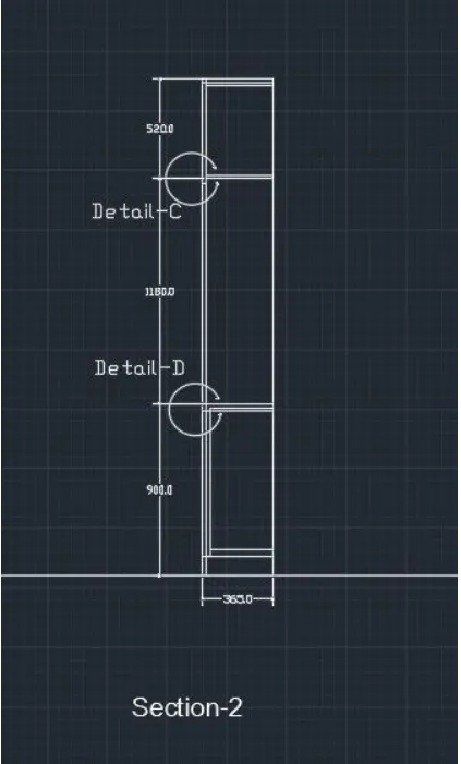
For Side Elevation, Use the line and offset it with size of 520, 1180 and 900 mm from above with command as per drawing and specify the dimensions.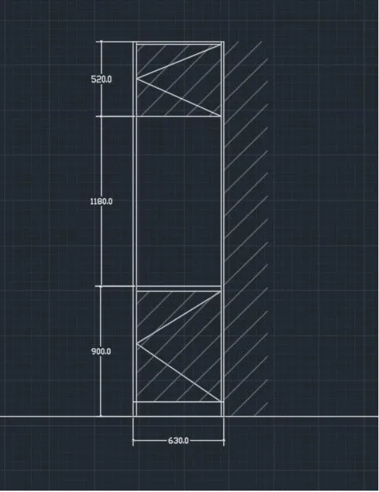
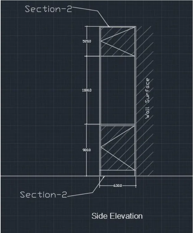
For Section-1, copy the side elevation and do editing in the different middle components in the drawing.
Use QLEADERS command to show the section.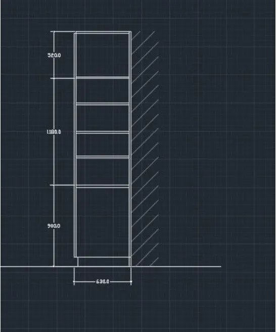
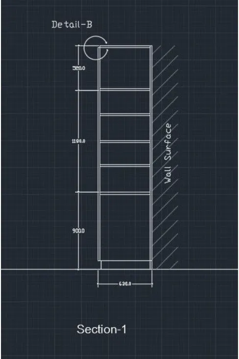
Section 2
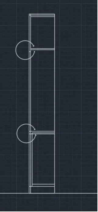
For plan view, Take rectangle sizes 630 X 2800.
do the dimensioning as per the drawing
In the command line type Qleader to annotate the
section-1.
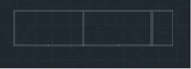
This is the Plan View Of wardrobe. (Above Image)
2
Aim:
Sketching the floor plan as shown in the Figure. Using the proper drafting tools to sketch the plan.
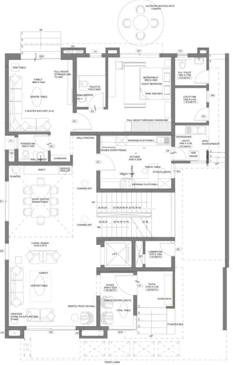
Procedure:
Units are set in mm.
Type Xline in command line and offset it with particular
distances like 9" of wall, living, toilet etc.
Draw the doors with line and arc command.
Draw the window with line and offset command.
Use dotted line to show lawn area.
The Procedure of drawing is shown below.
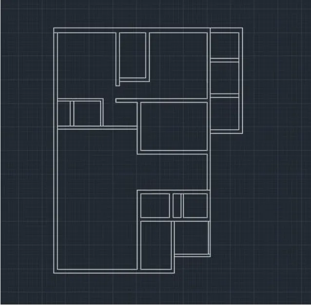
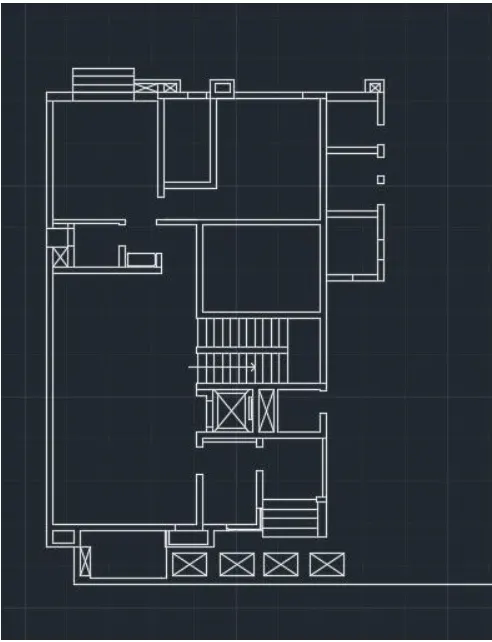
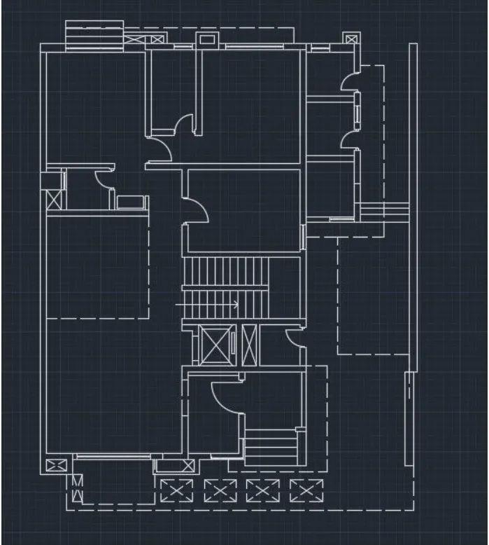
■Now, use text command to show text in the drawing. Use layer command to provide different layers in the drawing.
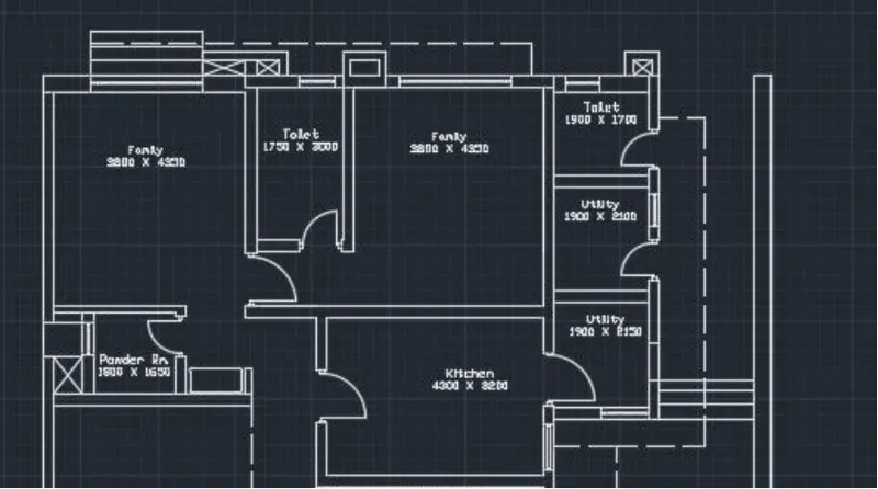
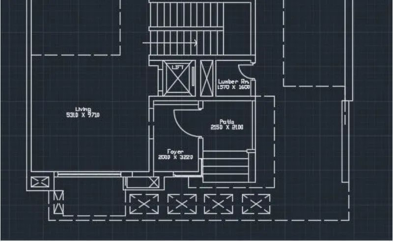
Give the dimensions in text and Annotate the drawing with text.
Result :
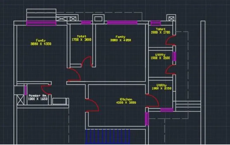
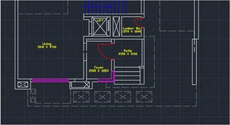
This is the final drawing of the Floor Plan.
3.
Aim:
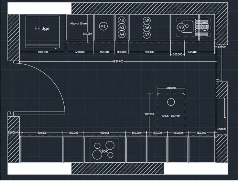
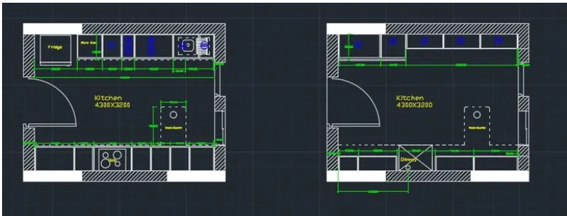
Creating the Kitchen Layout as shown in the Figure below. Also, using proper dimension techniques to dimension the kitchen layout.
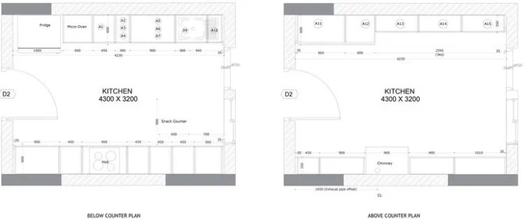
Procedure:
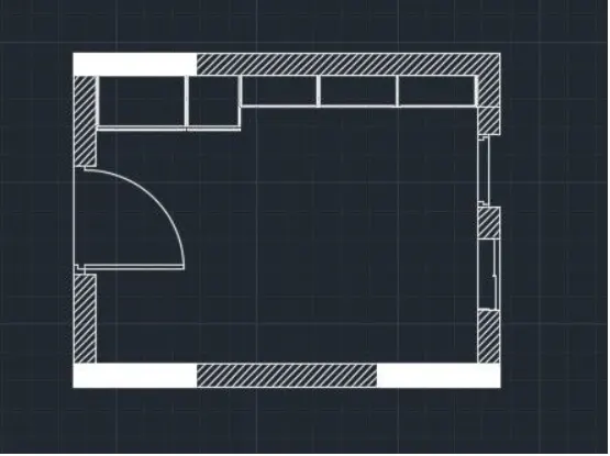
Type Line command and draw rectangle of size 4700 X
3700.
Type offset command of size 250 mm inside the
rectangle.
Draw the door using line and arc command.
Draw the window as per the drawing.
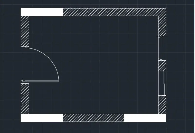
Then Offset the lines with size of 1000, 600, 450,300, 900,
945, 35.
And make the Platform and Fridge.
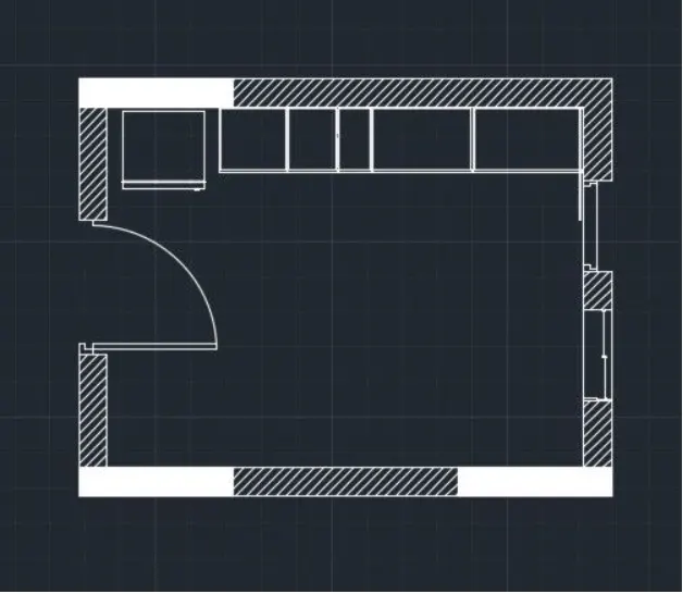
Draw the same platform at the other side.
Type offset command of size 35, 900, 450, 900, 450, 450, 450, 560, 35.
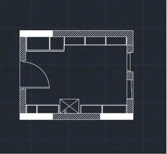
using dotetd line draw snack counter of size 600 X 700.
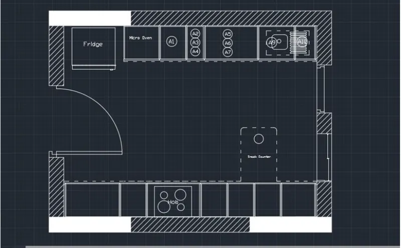
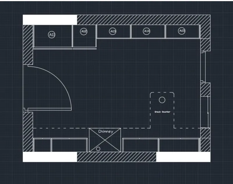
For above counter plan, use same rectangle box as used
before. Use line and offset command to make proper platform.
Draw the same at other side.
But the sizes are different with compared to below counter plan.
Annotate proper text and dimensions as per drawing.
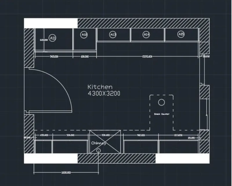
use layer command to show different layers that are used in the drawing.
Result :
4.
Aim:
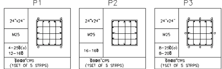
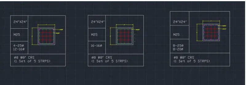
■ Sketching the column details as shown in Figure.
Procedure:
Using rectangle and Line commannd, draw table as per
drawing.
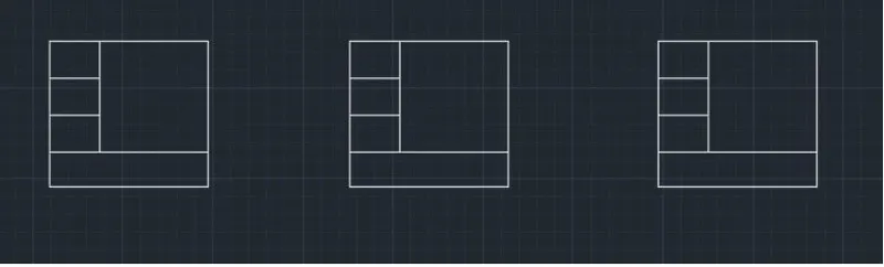
Draw the columns as per the sizes given in the drawing. Use the line, rectangle and circle command.
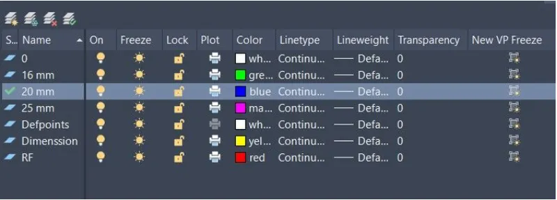
• Use different layers that are used in the drawing:
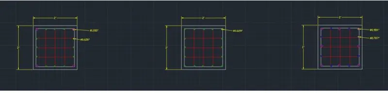
Draw the columns as per the sizes given in the drawing.
• Use the line, rectangle and circle command.
Use different layers that are used in the drawing.
Shown the layers which are used in the drawing.
Result :
5.
Aim:
To draw the raft layout.
Procedure:
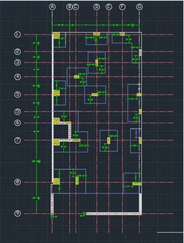
■ Draw the rectangle of size 29' x 60'.
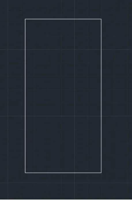
Use ISO Long dash- Short dash line to show the grids. Offset the lines as per drawing.
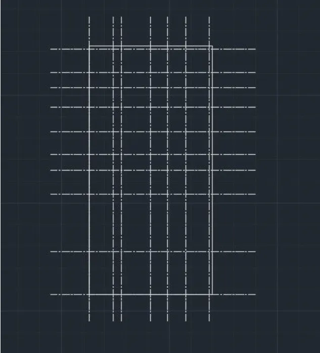
• Draw the column placements given in the drawing and
draft the column. Use Hatch command as shown in drawing.
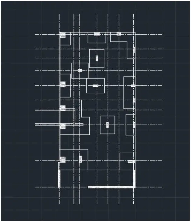
Mark the name of grids.
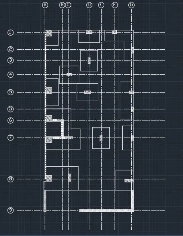
Use layers command to sshow the different layers in the
drawing.
Annotate wit hproper dimensioning in the drawing.
Result :
Conclusion:
ALL RESULT OF EACH DRAWING HAS BEEN ATTACHED WHICH WAS TAKEN FROM AUTOCAD