Creating a Wardrobe detailed drawing, Floor Plan, Kitchen Layout and Column Detail using AutoCad
1.ANS
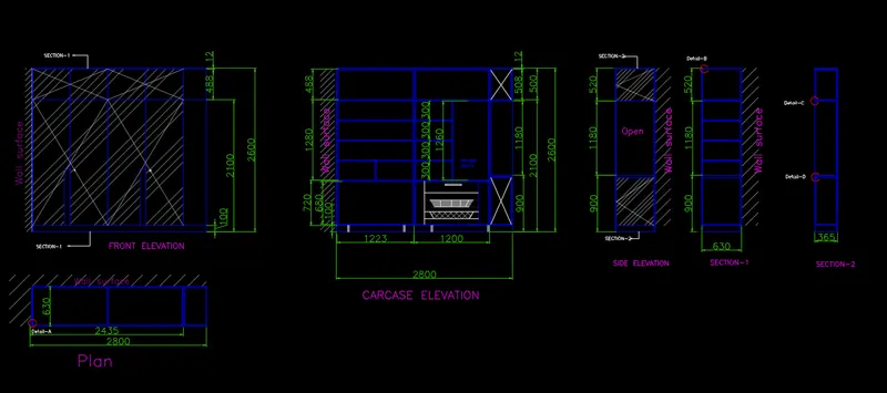
AIM: To Draw the elevation and details of a wardrobe using AutoCAD
introduction: draw the details of wardrobe plan, front elevation, carcase elevation, section-1 and section-2, side elevation
using the tools line tool, trim, offset, layers and what we required tools are used to draw the wardrobe details
open the AutoCAD and set units as decimal create the layers of walls, text, dimensions etc.
procedure:
plan:
- select the line tool and draw the distant of 2800mm
- select the offset and given distance is create the rectangle 5mmx5mm
- select the line tool and in y-direction 630mm
- select the offset 20mm
- offset 2435mm
- offset 10 given the twice forward direction
- offset 365
- offset 1217.5
- offset 10
- given dimensions of dim linear
- select the hatch and given the wall surface
- select the text and single line text create the text
front elevation:
- select the construction line project the plan
- select the offset of 12mm
- select the offset 488mm
- offset 100mm
- select the multi leader and leader structure set 3 points and draw the section-1
- select the line tool and set transparence set 50 % and draw the cross line
- select the hatch pick point and given the hatch
- select the dimensions and given every section dimensions
CARCASE ELEVATION:
project the front elevation wall and select the line tool and draw one line
select the offset and 2800 and 12mm, 1223, 1200
offset 10 mm
trim the extra lines
offset 20mm and offset 300mm repeat the 3 times to create wardrobe
select the offset 600mm
select the dimensions and given the dimensions
SIDE ELEVATION:
Projecting the wall thickness of carcase and draw one line select the off of 12mm and offset 630mm
select the trim and trim the extra lines select the dimensions and given dimensions
SECTION-1
projection lines of carcase elevation and draw one line and select the offset distance is 12mm and 630mm and trim the extra lines
SECTION-2
Projecting the lines and draw the one line select the offset 12mmans 365mm trim the extra lines are trimmed and s
select the dim linear and given the dimensions
select the walls and given the layers of wall color is blue created
layer dimensions are created and select the all dimensions and given dimension layer
RESULT:
2. ANS
AIM: to draw the floor plan by reference given plan to use the auto cad
Introduction:
using the reference plan to draw the floor and using proper tools in auto cad and the dimensions of wall thickness is 230 mm and interior wall is 150 mm and all dimensions are used in the drawing is mm.
Procedure:
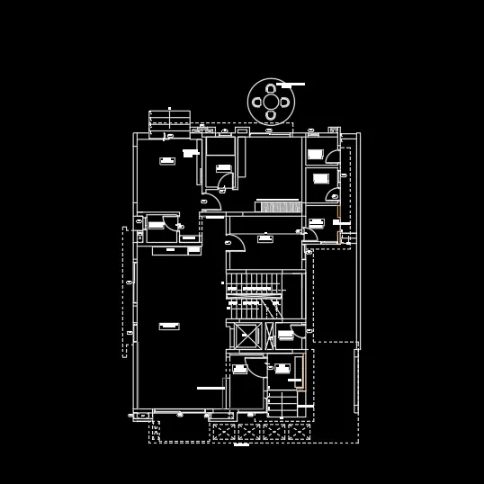
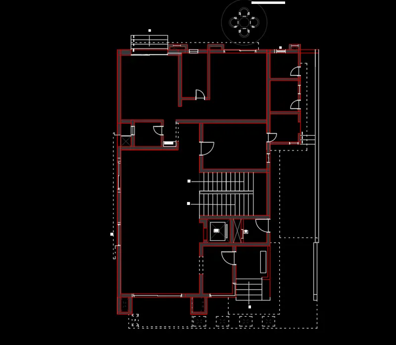
1. open the AutoCAD and set units metric
2. select the construction line draw the one horizontal and vertical one offset is taken the 230mm and given
3. offset 9710mm
offset 230mm
offset 1650mm
offset 230
offset 4350mm
offset 230mm
offset 3880mm,0ffset 230mm, offset1750mm, offset150mm, offset3830mm, offset230mm, offset 1900mm, offset230mm
select the trim and trim the extra lines
select the offset of distance 1700,150,2100,150,2150,150 mm
offset off kitchen 4300 ,230, 3200 mm
select the trim and extra lines are trimmed
offset lift and lumber RM. 1570mm offset 150mm, offset distance through offset 230mm
trimmed extra lines
dining/ living offset 5310mm and offset 230m offset 2000 and offset230mm offset 2150mm offset 150mm trimmed extra lines
creating of doors and windows by using the line tool and offset and trim using the dimensions ofD2-900mm width and D3- 600mm windows and ventilators are roughly taken
steps:
using the rise is 150mm and tread is 300mm
take line command draw the line offset 300mm given each step
outdoor seating with canopy:
select the circle and draw the one and select the circle draw inner side of the circle and create the chair using polar array and number of items are 4 and select the center of the circle and enter
3. ANS
AIM: TO draw the kitchen plan of below counter plan and above counter plan using auto cad
introduction: using the reference kitchen plan to draw the kitchen plan in auto cad by using the line and offset tools
procedure:
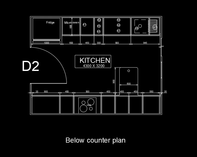
- open autocad and set as the units in metric
2.select the rectangle dimensions 4230x3200 mm
3. select the offset of 35 mm
4. select the offset and given the values are 35, 1000,600, 450,300,900,300,300,35 all dimensions in mm
5. offset 20 mm each end is given both sides
6. offset selected and given the values are 35,900,450,900,450,450,450,560,350 all dimensions are in mm
7. select the offset of 20mm and given each end given both sides offset 600mm given
8. select the trim and extra lines are trimmed
9. select the text single line and height s 20mm
10. select the circle and 50 mm diameter select the text single line and write text A1, A2, A3, A4.......A10
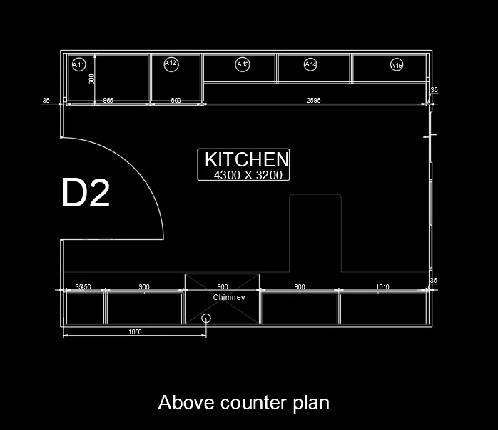
select wall door window enter copy the object
and select the offset given values are 35,965,600,865,865,865,35
offset 20 is given each end of both sides
offset 600, 350 mm
trim extra lines
offset select the given values are 35,450,900,900,900,1010,35
offset 20 is given each end of sides thickness
trimmed the extra lines
select the text and write text as KITCHEN 4300 X3200
and CHIMNEY
4.ANDS
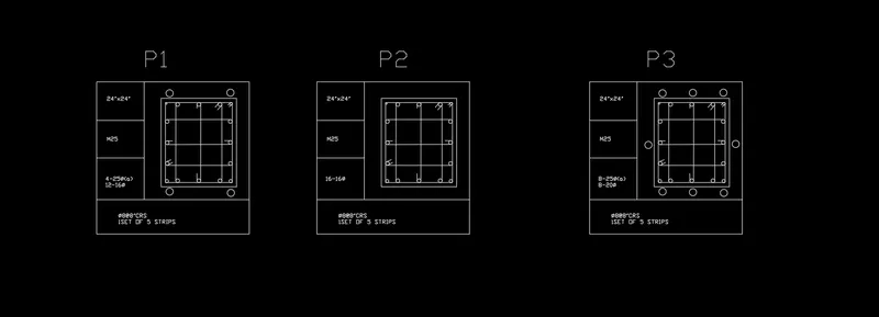
AIM: Sketch the column details as shown in Figure.
INTRODUCTION:
Insert dimensions and text in the figure. Refer to the bar sizes from the schedule.
8mm ---- 0.31 Inches
25mm--- 1 inches
16mm—0.62 inches
PROCEDURE:
1 select the units as engineering
2 select the rectangle drawn
3 select the line command and divide parts
4 select the rectangle drawn
5 offset is 2"
6 select the circle with radius
as per reference drawn the circles
8mm ---- 0.31 Inches
25mm--- 1 inches
16mm—0.62 inches
select the line command drawn the bars
5.ANS
AIM: Draw the Raft Layout as shown in the Figure.
INTRODUCTION:
Assuming the column size as per my knowledge. i can take the sizes as: 24”x24”, 9” x 24”, 9” x 18”, and 9’ x 24” .pdf to ensure the missing dimensions are assumed
procedure:
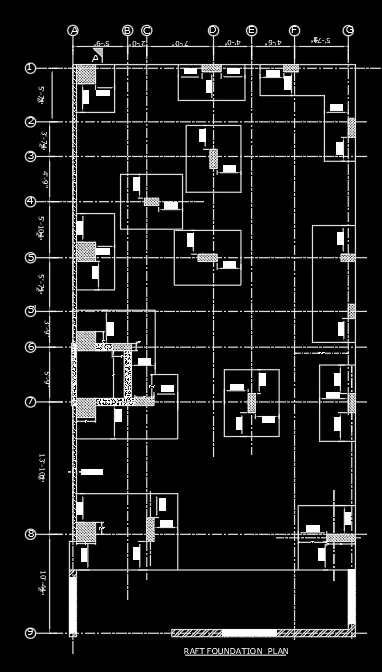
1 select the construction line and draw one horizontal and vertical
2 offset brick wall is 9"
3 the grid lines are given the offset of as per reference diagram
10-'4.5"
13'-10.5"
5'-9"
3'-9"
5'-7.5"
5'-10.5"
4'-9"
3'-7.5"
5'-7"
5'-6"
2'-0"
7'-0"
4'-0"
4'-6"
5'-7.5"
0-'9"
4. select the trim and trimmed the extra lines
5. column as reference pdf to drawn
offset is 6'8"
column sizes are 2' x2' and 2'x9" are drawn
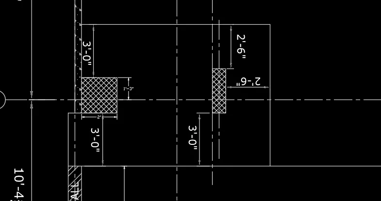
all columns are drawn as per reference diagram