Creating a Wardrobe detailed drawing, Floor Plan, Kitchen Layout and Column Detail using AutoCad
Aim:
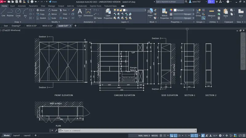
To draw the elevation and section of wardrobe. Provide the dimensions and text by the use of layers.
Procedure:
- Using the rectangle tool to create the rectangle of size 2800*630mm and explode it.
- Then offset the left, top and bottom at a distance of 12mm and divide the line into 2 segments.
- create a line at the point and offset 6mm both the sides.
- Then offset the right side at a distance of 365mm and using trim, trim the unwanted lines. The plan of the wardrobe is created.
- To create the front elevation create a rectengle of size 2800*2600mm and explode it.
- Then offset the left and top side at a distance 12mm. Then offset the bottom line at 100mm.
- Then offset the top line at 488mm and offset the right side line at 353mm
- Now divide the center bottom line into 2 segments and create a line.
- Then divide the right and left space into 2 segments and create a line.
- using trim command trim the unwanted lines. The front elevation is created.
- To create the carecase elevation do the same procedure of fornt elevation upto divide the line into 2 segments.
- Then offset the all the inner lines at a distance of 20mm.
- Offset the bottom line at 680mm and again offset it 20mm.
- Offset the last offseted line at 300mm in 4 times and offset the lines at 20mm. The selves are created.
- Then offset the right side space at 500mm and 180mm the drawers are created.
- Offset the center line at 600mm and trim the other side.
- Then offset the right side bottom line at 900mm and top line at 508mm.
- Using trim, trim the unwanted lines in the elevation. Carecase elevation is created.
- To create the side elevation, create rectangle of size 630*2600mm and explode it.
- Offset the sides at 12mm Then offset the bottom line at 100mm.
- Offset it again 900mm. Then 1180mm and 520mm. Then side elevation is created.
- To create section 1, create a rectangle of size 630*2600mm and explode it.
- Create construction lines in the carecase elevation and trim the unwanted construction lines. The section 1 is created.
- To create section 2, follow the same procedure of section 1 and create only the top and bottom sections. The section 2 is created.
- Create tha layers, dimensions, text.
- Create a dimention at the required sides and create a text whatever needed.
- Put the dimensions in dimention layer and text in text layer.
Result:
The plan and elevation of the wardrobe is created and the dimensions and the text are placed in the proper manner.
NOTE: I attached the Autocad file the dimensions are not clearly visible in the screenshoot.
Aim:
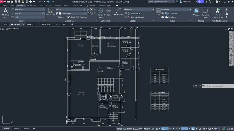
To draw the floor plan by using proper drafting tools.
Procedure:
- The thickness of external and internal wall is 230mm and 150mm.
- The doors and windows size are assumed and mentioned in the drawing.
- The stair raiser is 150mm and thread is 300mm.
- using construction line create the vertical and horizontal line.
- Offet the lines at a distance of 230mm and using trim and fillet command trim the unwanted lines.
- Offset the horizontal line at 9710mm and again offset it 230mm. The living/dining area is created.
- Then offset the line at 1650mm and at 150mm. Then offset the y axis line at 350mm Then at 230mm Then 1800mm. The utility room is cretaed.
- Then offset the horizontal line at a distance of 4350mm and at 402mm.
- Offset the vertical line at a distance of 3880mm and again 230mm and again 1750mm and 150mm. Then offset the top line at 230mm and 3000mm. The family and toilet area is created.
- Then offset the vertical line at a distance of 3830mm and at 230mm, 1900mm and at 150mm.
- Offset the top horizontal line at a distance of 4500mm and at 230mm. The guest bedroom is created.
- Then offset the top horizontal line at a distance of 1700mm and at 150mm. The D.H. Toilet is created.
- Offset the line at 2100mm and at 150mm. The utility room is created.
- Then offset the line at 2150mm and at 150mm. The other utility room is created.
- Then offset the bedroom side line at 3200mm and at 230mm. Kitchen is created.
- Offset the kitchen line at 2822mm and at 230mm and create the rectangle of size 3375*300mm and create the threads of the stairs of size 300mm each thread.
- Offset the stair wall line at 1600mm and at 230mm.
- Then offstet the side wall line at 1570mm and at 150mm and then 300mm and 230mm. Then offset 1656mm and at 150mm. Lift area is created.
- Offset the living area side wall at 3220mm and at 230mm and offset the line at 2150mm and at 150mm. The foyer and patio area is created.
- Now by using trim and fillet command, trim the unwanted lines.
- Create the steps in the patio area and family area.
- place the doors and windows in the required places.
Result:
The floor plan is drawed by using construction line, line, fillet, offset and other drafting tools.
NOTE: I attached the Autocad file the dimensions are not clearly visible in the screenshoot.
Aim:
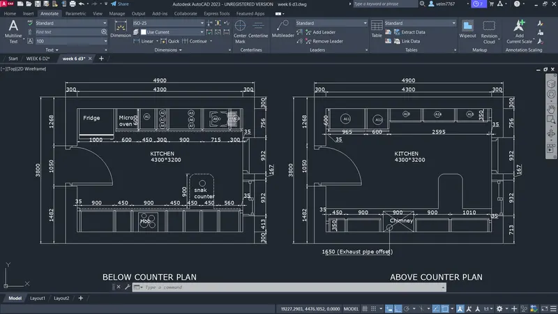
To create the kitchen layout by using proper drafting tools and dimension using proper dimension techniques.
Procedure:
- using rectangle tools create the rectangle of size 4300*3200mm and offset the rectangle at a distance of 300mm in the outer side.
- By using trim and fillet tool, trim the unwanted lines and Then explode the rectangles.
- Place the door of size 1050mm and window of size 932mm of two windows.
- Make the copy of the created kitchen.
- Then offset the left side wall line to the following distances 1000mm, 600mm, 450mm, 300mm, 900mm, 35mm respectively.
- Offset the upper wall line at a distance of 600mm then using the fillet and trim command create the fridge, oven and others.
- Then offset the bottom line at a distance of 600mm.
- Offset the left side wall line the following distances 35mm,900mm, 450mm, 450mm, 450mm, 560mm and 35mm.
- Then using the trim tool, trim the unwanted lines to create the bottom snak counter and others.
- Ofset the another kitchen left side wall at a distance of 35mm, 965mm, 600mm, 2595mm respectively.
- Offset the upper wall line at a distances of 350mm and 600mm.
- Then by using trim tool, trim the unwanted lines.
- Then by using the same procedure create the bottom furnitures.
- By using text tool, create texts to a required places and dimension using the continuous technique.
Result:
The kitchen layout is created by using the proper drafting tools and dimensions are done by using continuous dimension technique.
Aim:
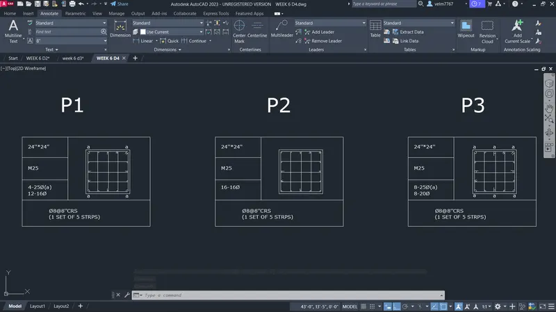
To create the column details of size 24''*24'' columns.
Procedure:
- Create a rectangle of size 24''*24'' and offset the rectangle at 1'', then explode the inner rectangle.
- Then create the main bars of size 0.5'' and 0.31'' by using circle tool.
- Then fillet the corners of the inner rectangle of radius 0.5''
- Then place the circles in the required positions in the inner rectangle.
- Then by using tangent snaping option create a line of striups in the required directions to tangent the circles.
- Create hooks of the striups by using tangent snaping option to the required positions.
- Then create the table by using the lines, offset and trim command.
- Then enter the text required in it.
- Follow the same procedure to another two columns.
Result:
The column details are created by using the rectangle, line, circle, offset and trim tools.
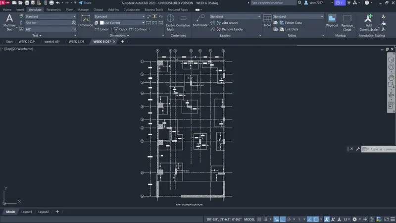
Aim:
Draw the raft layout and assume the column sizes.
Procedure:
- Using construction line create a vertical and horizontal line.
- Offset the horizontal line to the following distances 10'4.5'', 13'10.5'', 5'9'', 3'9'', 5'7.5'', 5'10.5'',4'9'', 3'7.5'' and 5'7.5''
- Then offset the vertical line to the following distances 5'9'', 2'0'',7'0'',4'0'', 4'6'' and 5'7.5''
- Then create a column size 24''*24'' at the grid 8 of A and column of size 9''*24'' at the grid 8 of C.
- Offset the rectangle of size 24''*24'' at a distance of 3' and explode it and offset the column of size 9''*24'' at a distance of 3', then trim the unwanted lines.
- Then create a rectangle of size 24''*24'' at the grid 7,A and 6,A and create the column of size 24''*9'' at the grid 6,B in the vertical direction.
- Create a column of size 24''*9'' at a grid 7,C in the vertical direction and connect the columns by using lines to create a concrete wall.
- Then create a column of size 24''*24'' at the grid 5,A and offset it at a distance of 3' and explode it and move the right side line at 2' form the column created.
- Then create a column of size 18''*9'' at a grid 4,C and column of size 24''*24'' at a grid 1,A
- cerate a column of size 24''*9'' at a grid 1,D and column of size 9''*24'' at a grid 3,D and column of size 18''*9''
- Create a column of size 24''*9'' at a grid of 2,G and column of size 18''*9'' at the grid 4,G
- create a column of size 9''*18'' at the grid 5,G and column of size 9''*18'' at a grid 7,G
- create the respective offset and trim the unwanted lines to create the foundations.
- Then create the walls of 9'' and 4.5'' at the required place.
Result:
The raft layout is drawn by using the construction lines, offset, rectangle and other drafting tools.
NOTE: I attached the Autocad file the dimensions are not clearly visible in the screenshoot.