Creating a Wardrobe detailed drawing, Floor Plan, Kitchen Layout and Column Detail using AutoCad
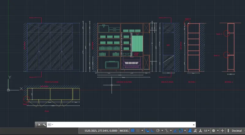
1. Draw the elevation and details of a wardrobe as shown in the Figure below. After sketching, you need to provide the dimensions and text with the use of layers. Use proper text styles and dimension methods to document it. Also, assume dimensions, wherever needed.
Note: All dimensions are in mm.
SOLUTION 1:
AIM: To draw the elevation and details of the wardrobe given in the figure and providing the dimensions and texts using the layer properties.
PROCEDURE: The procedure for drawing the details of a wardrobe as shown in the figure is mentioned below step wise and the screenshots attached for reference.
- Set the drawing as metric and decimal units.
- Set the dimension style and units to metric
- Set the drawing limits
- Set Zoom extents.
- Draw the outer lines of cupboard for front elevation using line command
- Offset the lines as per the drawing for the border.
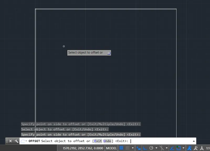
- Offset the lines for the vertical partitions of Wardrobe as per drawings.
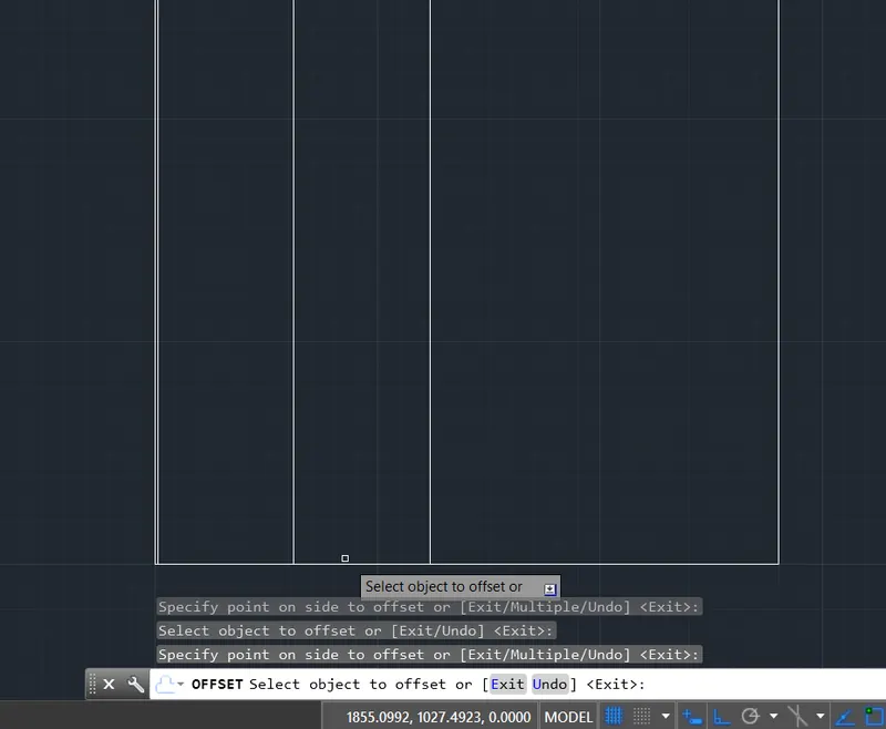
- Hatch the door laminate as per the figure by Hatch command and using appropriate scale and design.
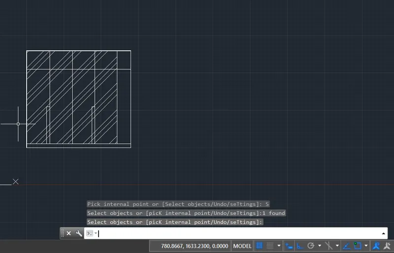
- Trim hatch from the unwanted hatched area
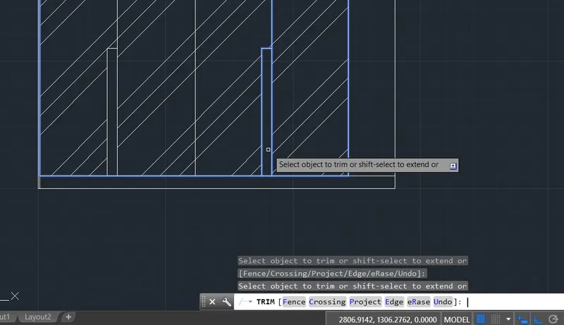
- Copy and paste the elevation drawing on side for the carcase elevation view
- Draw the lines in elevation for laminates as per the figure.
- Draw the plan of cupboard by extending from reference lines from elevation.
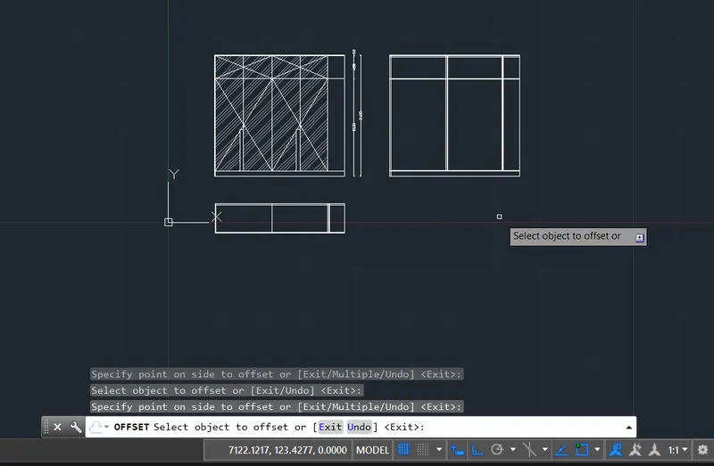
- Draw the horizontal lines for the partitions in carcase elevation view
- The dimensions are provided to elevation and plan using Dimlinear command for reference.
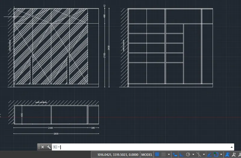
- After completing all the horizontal and vertical partitions of the carcase elevation, draw the various internal materials like baggage, clothing, drawers, hangers ets as per the figure using various commands like line, copy paste, array trim, circle, rectangle as per requirement
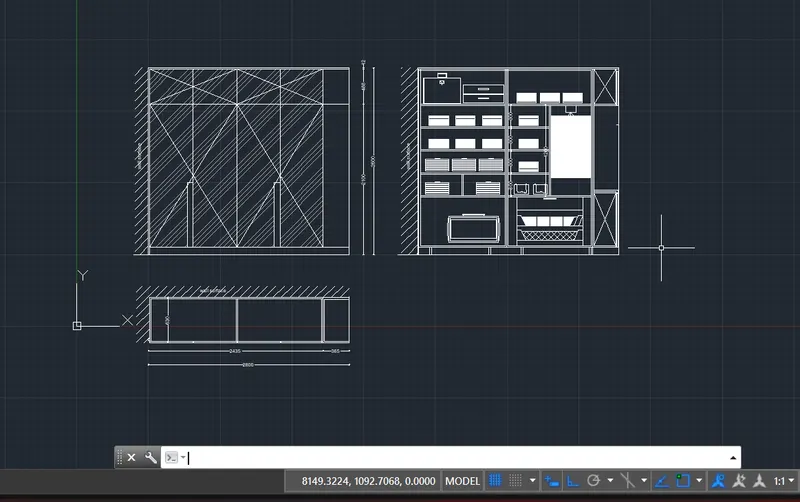
- Draw the side elevation and the section drawings
- Draw the door and swing in the plan using the arc command.
- Mirror command is used for the adjacent swings.
- Mark the detail circles using arc and drawing arrows
- Provide all the dimenstions as per the figure.
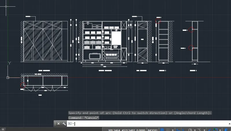
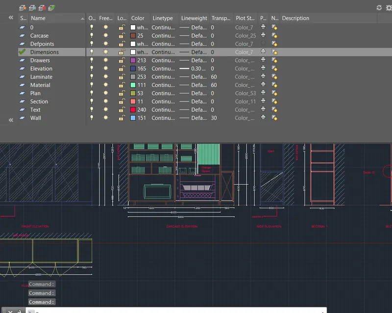
- Assign the layer properties for various lines
- Assign colour, lineweight, transparency for the layers
CONCLUSION:
Thus the given figure of details of wardrobe is created in the autocad using various tools and the dimensions and texts are provided using the layer properties.
Q2. Draw the floor plan as shown in the Figure. Use the proper drafting tools to sketch the plan. Do not hatch or draw the furniture. You need to draw the floor plan with the following:
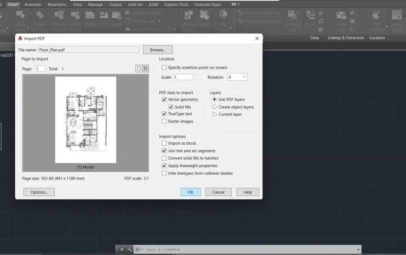
Note: You can also import the Floor_Plan.pdf into your current drawing and start working on the project. You need to scale the imported pdf file using reference option. All dimensions are in mm.
- Walls (Exterior and Interior)
Wall Thickness: Exterior Wall- 230mm, Interior Wall: 150 mm (Wherever Required)
- Doors and Windows: Assume the size of the doors and window.
2.1 Stairs: Tread-300mm, Riser-150mm
- Insert Text wherever required
- Insert the dimensions using proper dimension techniques
SOLUTION 2:
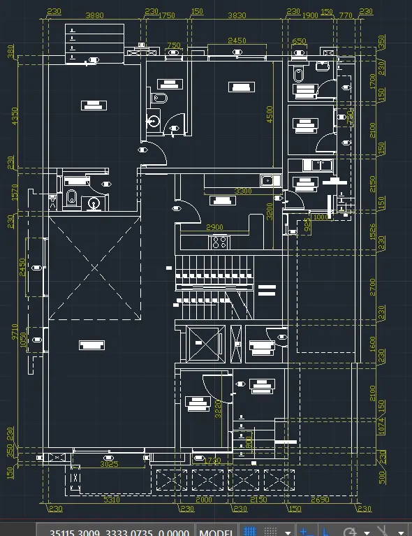
AIM: To draw the floor plan of a building in the figure using proper drafting tools in AutoCad by importing the PDF file in AutoCad for reference and checking the missing dimensions.
PROCEDURE: The procedure for drawing the floor plan as shown in the figure is mentioned below step wise and the screenshots attached for reference.
- Set the drawing as metric and decimal units.
- Set the dimension style and units to metric
- Set the drawing limits.
- Set zoom extents.
- Import the PDF file of floor plan to AutoCad
- Scale the imported plan to the drawing scale using Scale command and reference command.
- Draw the inner lines of rooms of the building as by using line command, offset, fillet etc command as per the given dimension
- Offset the lines as per the drawing for the wall thikness
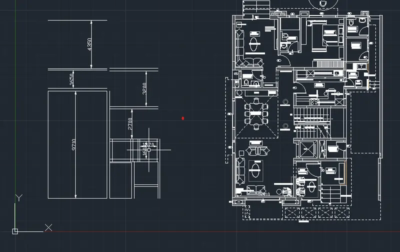
- Draw all the rooms using line command, offset command, trim command, extend command etc as per the dimensions from the given drawing.
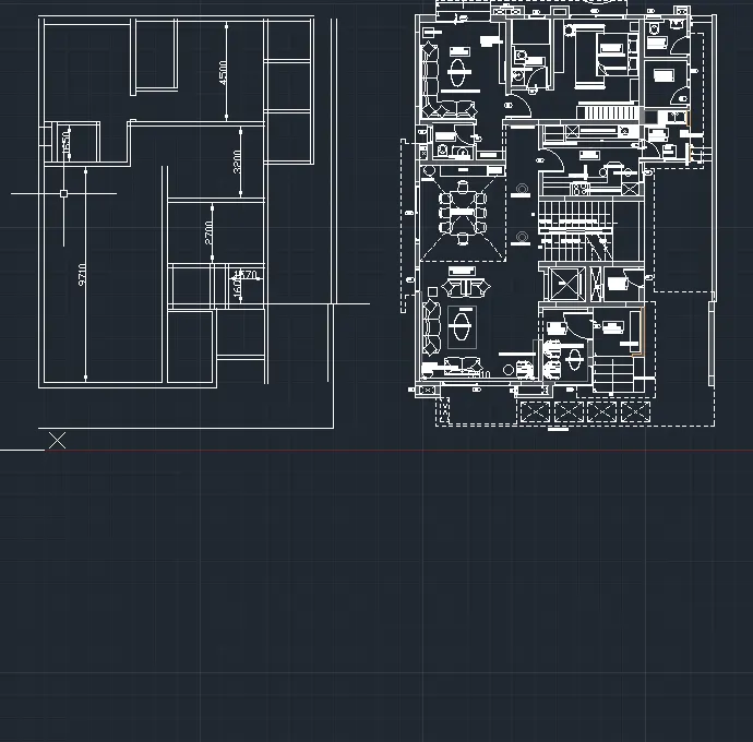
- Draft the various sizes of the doors along with the swing using line and arc commands.
- Group each door lines for easy use
- Mirror each door to create different orientations for easy and ready use in the drawing.
- Create the door openings as per the given figure.
- Copy paste the required door in the appropriate location as per the shown orientation.
- Change the canopy line to hidden line and set the hidden line using linetype scale
- Draw the steps, stairs as per the figure.
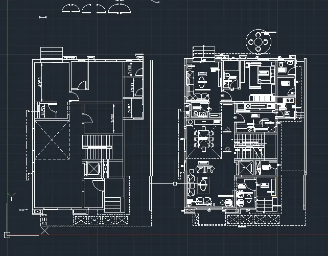
- Create the Door and Window tages using line, arc and mirror commands for ready use
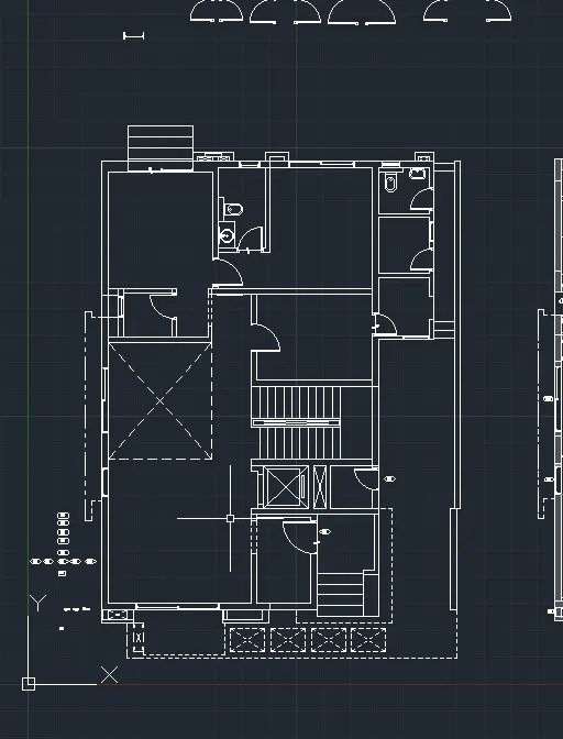
- Use the door and window tag and provide required number as per the figure
- Write the room names and dimensions using the Mtext and by modifying to required size and font.
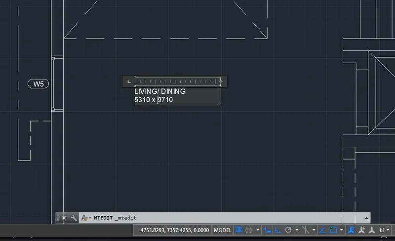
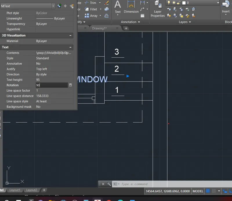
- Provide the text for step numbers and UPVC window
- Rotate the UPVC window text by 90 degrees as shown in the figure
- Complete all the dimensions using dimlinear command by setting appropriate dimension style.
- Use DimContinue command for continuous dimensioning of the building
- Provide box for room names and dimensions using the rectangle command.
CONCLUSION:
Thus we have imported the PDF floor plan drawing in Autocad for reference and drawn similar floor plan using various tools in Autocad and provide the dimensions for the building.
Q3. Create the Kitchen Layout as shown in the Figure below. Also, use proper dimension techniques to dimension the kitchen layout. Also, insert text wherever required. All dimensions are in mm.
SOLUTION 3:
AIM: To draw the Kitchen layout shown in the figure using proper drafting tools in AutoCad by importing the PDF file in AutoCad for reference and checking the missing dimensions.
PROCEDURE: The procedure for drawing the Kitchen plan as shown in the figure is mentioned below step wise and the screenshots attached for reference.
- Set the drawing as metric and decimal units.
- Set the dimension style and units to metric
- Set the drawing limits.
- Set zoom extents.
- Import the PDF file of floor plan to AutoCad
- Scale the imported plan to the drawing scale using Scale command and reference command.
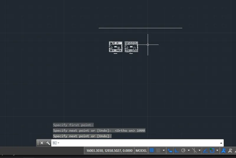
- Cut the required partial kitchen plan from the building plan drawn in the previous challenge and paste in the new drawing beside the imported kitchen layout PDF drawing.
- Trim the unwanted lines from the plan to create the Kitchen plan.
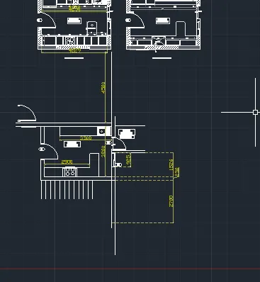
- Provide the partitions of cabinets below the platform as shown in the figure using, line command, offset command, copy paste command, trim, fillet etc commands.
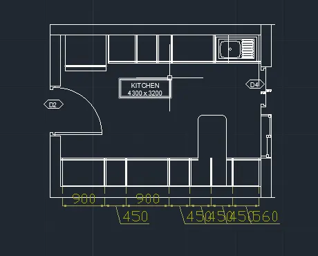
- Draw the fridge and adjust the sink layout as per the given figure.
- Create the circles for the tags as shown in figure
- Change the outer line of platform to hidden line
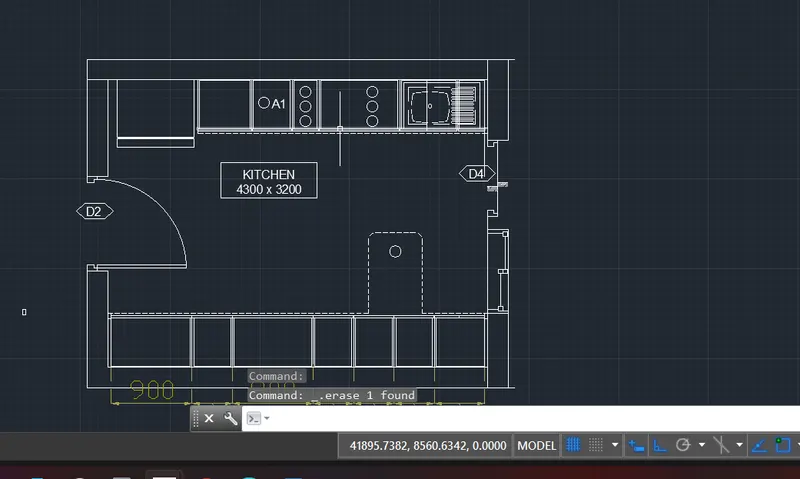
- Provide the dimensions for the cabinet spacings as shown in the figure.
- Use dimcontinue command for continous dimensioning
- Hatch the walls and columns as per the given figure.
- Use circles to create hob stoves
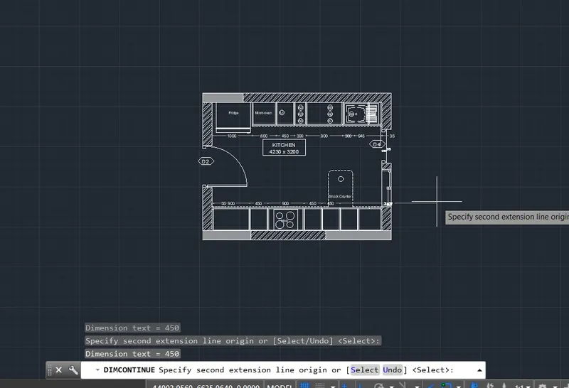
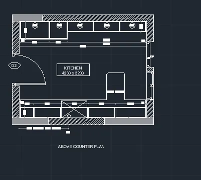
- Copy and paste the Below counter plan on side to create Above counter plan.
- Modify the cabinet partion spacings and size as per the figure
- Provide the dimensions as shown in figure
- Create centre line for the chimney exhuast
- Provide the tags for various cabinets as shown in the figure
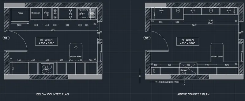
CONCLUSION:
Thus the drawing for the Kitchen layout shown in the figure is created using proper drafting tools in AutoCad by importing the PDF file in AutoCad for reference and providing the dimensions and tags
Q4. Sketch the column details as shown in Figure. Insert dimensions and text in the figure. Refer to the bar sizes from the schedule.
8mm ---- 0.31 Inches
25mm--- 1 inches
16mm—0.62 inches
SOLUTION 4:
AIM: To draw the column details as shown in the figure and inserting dimensions and texts.
PROCEDURE: The procedure for drawing the given column details as shown in the figure is mentioned below step wise and the screenshots attached for reference.
- Set the drawing as Imperial and Engineering units.
- Set the dimension style and units to Engineering
- Set the drawing limits.
- Set zoom extents.
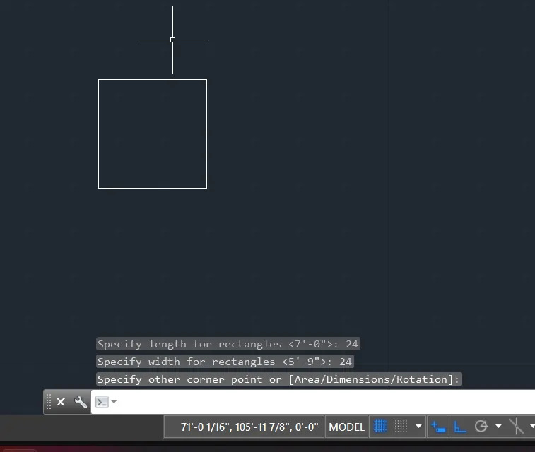
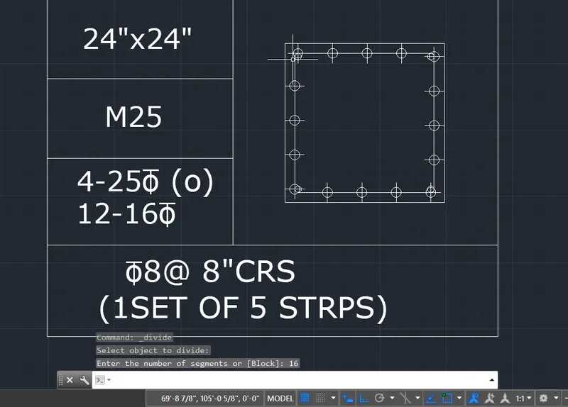
- Draw a square of 24" x 24" for column size using rectangle command
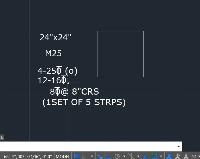
- Insert the texts for as per the column details in the given table using Mtext command by modifying the font and size as required
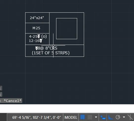
- Draft the table around the text and the column as shown in figure using line commands
- Draw the square for stirrups assuming 1.5" cover using the rectangle command
- Fillet the corners of square of stirrups using the radius of 0.5"
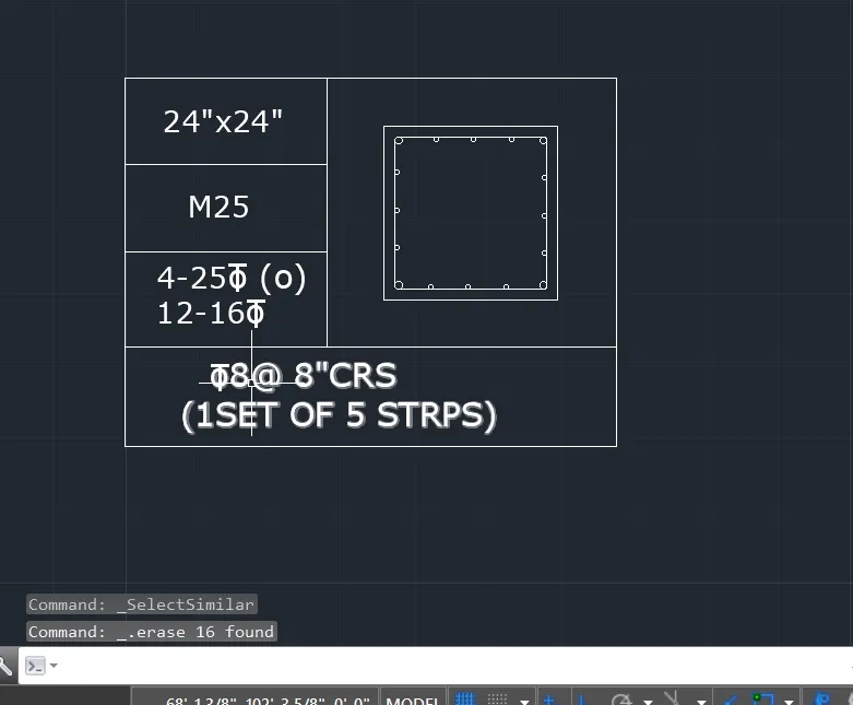
- Divide the square in 16 equal parts using the Point command to position the main reinforcement bar as shown in figure.
- Provide the circles of 1" for 25mm bars and 0.62" for 16mm dia bars and 0.8" for 20mm bars in the positions as shown in figure
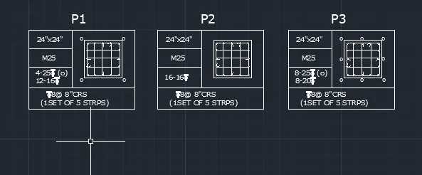
- Hatch the circles to show solid bars.
- Using line command draw the stirrup hooks
- Provide the 'o' mark for the reinforcement bars as shown in figure
- Provide the dimensions for the column and reinforcement bars using the dimlinear and dimdia commands and use multileader for showing the bar locations.
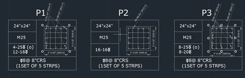
CONCLUSION: Thus the column details as shown in the figure are created in AutoCad showing the dimensions and texts as required.
Q 5. Draw the Raft Layout as shown in the Figure. Assume the column size as per your knowledge. You can take the sizes as: 24”x24”, 9” x 24”, 9” x 18”, and 9’ x 24”. You can import the raft_foundation.pdf to ensure the missing dimensions.
SOLUTION 5:
AIM: To draw the raft layout as shown in the figure by importing the PDF drawing in AutoCad for reference.
PROCEDURE: The procedure for drawing the raft layout as shown in the figure is mentioned below step wise and the screenshots attached for reference.
- Set the drawing as Imperial and Architectural units.
- Set the dimension style and units to Architectural
- Set the drawing limits.
- Set zoom extents.
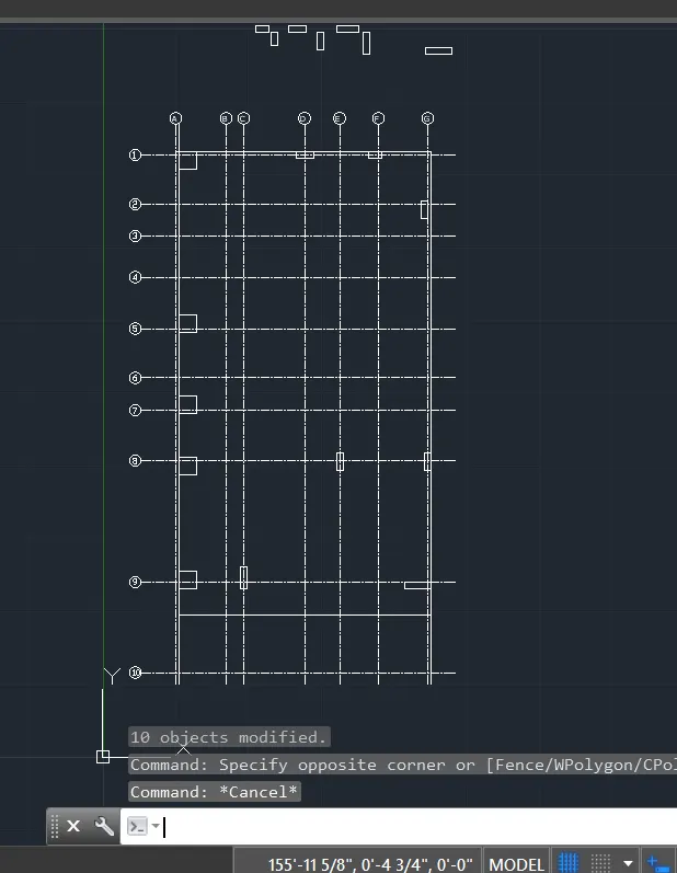
- Draw the horizontal and vertical lines for the column grid using line command, offset command, copy command, etc as per the given grid dimensions.
- Draw the various sizes of the columns of 24”x24”, 9” x 24” and 9” x 18” using rectangle command
- Copy and paste the each columns and rotate at 90 degrees for ready use in the layout
- Copy and paste the columns in the grid locations as shown in the figure
- Create the circles for the grid tags
- Modify the grid numbers by auto numbering using Autonumber tool from Express tool tab
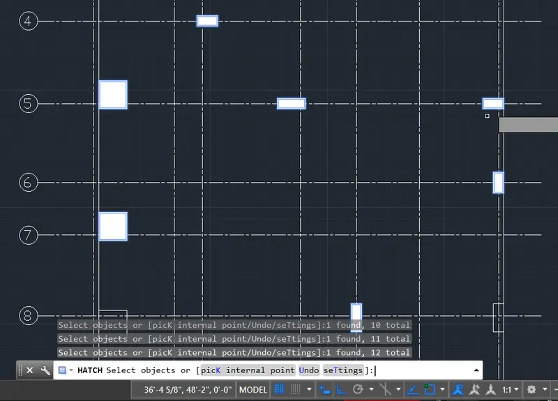
- Hatch the column rectangles
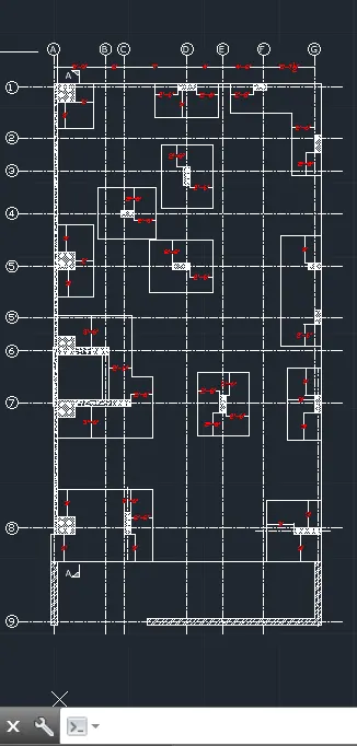
- Draw the footings as per the sizes shown in figure using rectangle command and line command
- Place the footings around the columns as per the distances shown in the figure.
- Draw the RC wall as shown in the figure and hatch it with concrete pattern.
- Draw lift RC walls as shown and hatch with concrete pattern
- Draw the brickwalls as per figure and provide the hatch pattern for brick wall
- Provide the dimensions as shown in the figure using dimlinear command and dimcontinue command for continous dimensioning and modify the dimensions line and text using dimstyle as required.
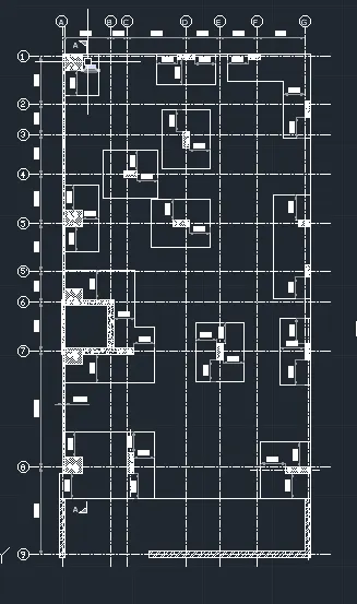
CONDLCUSION: Thus the raft layout as shown in the figure is drawn by importing the PDF drawing in AutoCad for reference and required hatch patterns and dimensions are provided.