Creating a Wardrobe detailed drawing, Floor Plan, Kitchen Layout and Column Detail using AutoCad
After 2nd question i also 4th then 3rd
Question 1)
Answer:
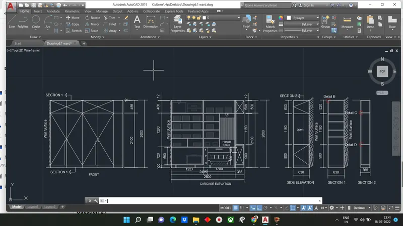
Aim: To create the plan, elevation and section views of a wardrobe as shown in fig
Introduction: The drawing consists of a plan showing from the top view and front elevation along with the car-case elevation showing all the inner elements of the wardrobe, side elevation and 2 section view
Procedure
Open Autocad
In startup setting start from scratch select metric (Meter)
Setup limits
Type UN in command box and press enter
Change units type decimal and precision to 0.00 and insertion scale to milimeters
STEP-1: Creating Plan View
Type Rec or rectangle
- Specify first corner point: Select any point on grid
- Specify other corner point or [Area: Dimension: Rotation]: Click on dimensions
- Specify length for rectangle: Type 2800 and press enter
- Specify width for rectangle: Type 630 and press enter and set the direction as first quadrant
Type 'o' or offset
- Specify offset distance: Type 20 and press enter
- Select object to offset: Select the rectangle drawn earlier and select the inside of the rectangle
- Explode two rectangles using explode command
- Move the left two edges to a distance of 12 to right and adjust other line using grip
Type 'o' or offset
- Specify offset distance: Type 1203 and press enter
- Select object to offset: Select the left edge of inner rectangle and click on right
Type 'o' or offset
- Specify offset distance: Type 1180 and press enter
- SElect object to offset: Select the last offset line
Type 'o' or offset
- Specify offset distance: Type 20 and press enter
- Select object to offset: Select the last offset line
- Select object to offset: Select the last offset line
- Trim off extra potions as shown in figure
- Draw door gaps using line command and trim extra portions
- Draw doors to plan using line command and curve command
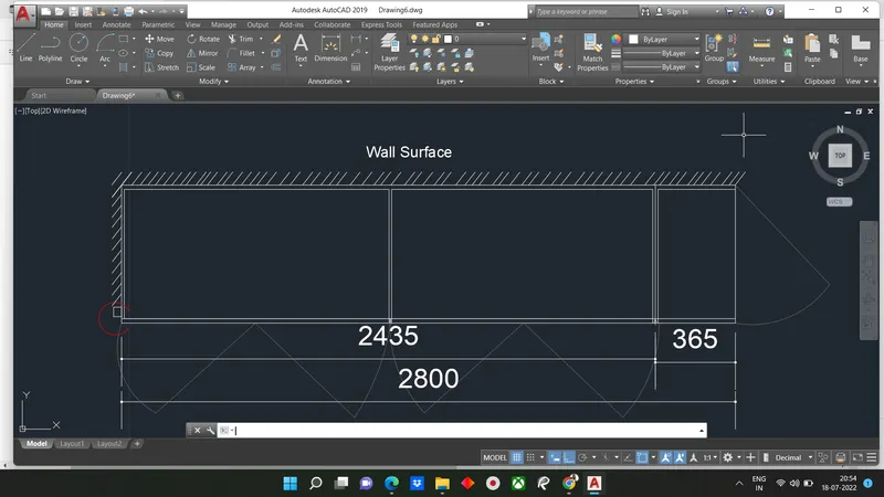
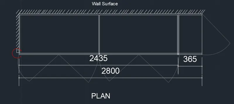
STEP-2: Creating Front Elevation
Type Rec or rectangle in command box or select rectangle from the draw toolbar
- Specify first corner point: Select any point on grid
- Specify other corner point or[Area: Dimension: Rotation]: Click on dimension
- Specify length for rectangle: Type 2800 and press enter
- Specify width for rectangle: 2600 in command box
Type 'o'
- Specify offset distance: Type 12 and enter
- Select object to offset: Select the rectangle drwan earlier and select the inside of the rectangle
Explode both rectangles and delete right and bottom edge of inner rectangle
Type 'o' or offset
- Specify offset distance: 1223 and press enter
- Select object to offset: Selectleft edge of inner rectangle and click on right
Type 'o'
- Specify offset distance: Type 1200 and press enter
- Select object to offset: SElect the last offset line
TYpe 'o'
- Specify offset distance: Type 100 and press enter
- Select object to offset: Select the bottom edge of outer rectangle and click on top
Type 'o'
- Specify Offset distance: Type 488 and press enter
- Select object to offset: Select the right edge of outer rectangle and click top
Type 'o'
- Specify offset distance: Type 600 and press enter
- Select object to offset: Select the line drwan at an offset 1223 from left edge
Trim all extra portion draw cross line for all door area
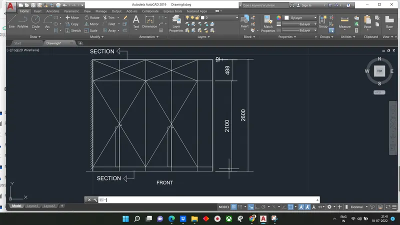
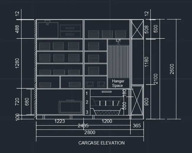
STEP-3: Creating Car-Case Elevation
Type Rec
- Specify first corner point: Select any point on grid
- Specify other corner point or[Area: Dimension: Rotation]: Click on dimension
- Specify length for rectangle: type 2800 and press enter
- Specify width for rectangle: Type 2600 and press enter and set direction as first quadrant
Type 'o'
- Specify offset distance: Type 12 and press enter
- Select object to offset: Select rectangle drawn earlier and Select the inside of the rectangle
Explode both rectangle and delete right and bottom edge of inner rec
Type 'o'
- Specify offset distance: Type 1223 and press enter
- Select object to offset: Select left edge of inner rectangle
Type 'o'
- Specify offset distance: Type 1200
- Select object to offset: Select last offset line
Type 'o'
- Specify offset distance: Type 100 and press enter
- Select object to offset : Select the bottom edge of outer rectangle click to top
Type o'
- Specify offset distance: Type 488 and press enter
- Select object to offser: Select the right edge of outer rectangle
Type 'o'
- Specify offset distance: Type 20 and press enter
- Select object to offset: Select the last offset line and click on bottom
Trim off extra portion
Type 'o' or offset
- Specify offset distance: 680 in command box
- Select object to offser: Select bottom edge of inner rectangle offset at 100mm and click at top
Type 'o'
- Specify offset distance: type 320
- Select object to offset for 3 times at top
Type 'o'
- Specify offset distance: Type 2 and press enter
- Select object to offset for 4 times at bottom
Using rectangle command draw series of wardrobe components as shown in fig
Trim extra lines
Type 'o'
Specify offset distance: 900 and enter
Select object to offset : Select bottom edge & click on top and trim off left portion
Type 'o'
- Specify offset distance: Type 1180 and press enter
- Select object to offset select last offset line& click at top
- Create thickness offset 2 on both side
- Using line command drawn cross line
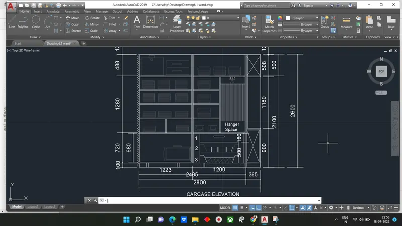
Result as shown fig
We are creating components in wardrobe by reducing transpancy level
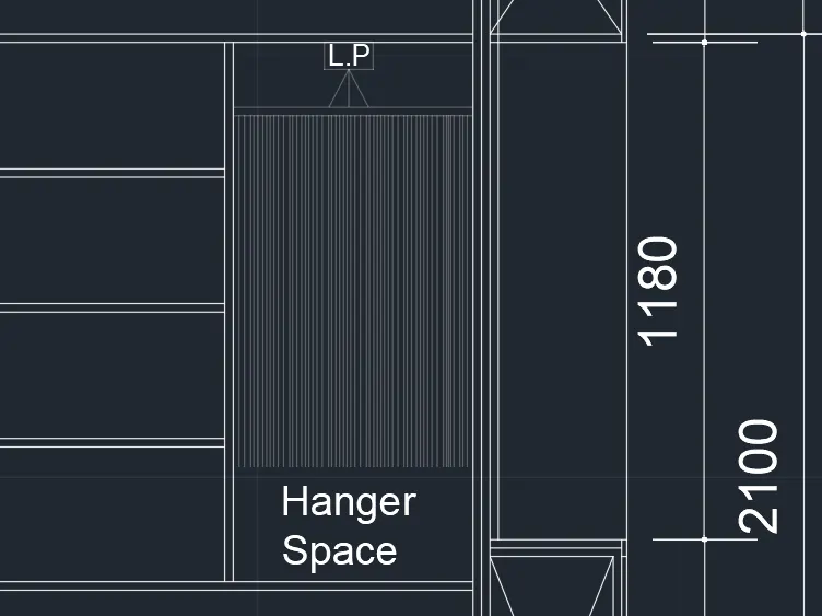
STEP-4: Creating Side Elevation
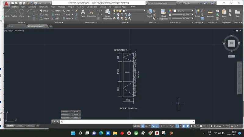
Type rec or rectangle
- Specify first corner point: Select any point on grid
- Specify other corner point or [Area: Dimension: rotation] Click on d
- Length: 630
- Width: 2600
Type 'o' or offset
- Specify offset distance: type 20
- Select object to offset: Select recatangle drwan earlier and inside of the rectangle
- Select both the rectangles and type Explode and press enter
Type 'o' or offset
- Specify offset distance: Type 100 and press enter
- Select object to offset: Select the bottom edge of outer rectangle and click
Type 'o'
- Specify offset distance: Type 800 and enter
- SElect object to offset: Select the last offset line and click on top
Type 'o'
- Specify offset distance: Type 500 and press enter
- Select object to offset: Select top edge of inner rectangle and click on bottom
Create thickness offset 2 both lines
Draw cross line using line command
STEP-5: Creating Section -1 Elevation
Type Rec or rectangle
- Specify First corner point: Select any point on grid
- Specify other corner point or [Area:dimension:Rotation] : Click on dimension
- Length 630
- Width 2600
Type 'o'
- Specify offset distance: Type 20 and enter
- Select object to offset: Select rectangle drawn earlier and select inside of rec
- Select both rec and explode
Type 'o'
- Specify offset distance distance: 100 annd press enter
- Select object to offset bottom edge of outer rectangle and click on top
Type 'o'
- Specify offset distance: type 800
- Select object from bottom edge of outer line and click on top
Type 'o'
- Specify offset distance: Type 500 and press enter
- Select object to offset at top edge of inner rectangle and click on bottom
Type 'o'
- Specify object distance: type 320 and press enter(3 times)
- Select object to offset: Select last offset line and click on bottom
Type 'o'
- Specify offset distance 20
- Select object to offset from last line an click on bottom for 4times
- Select object offset" Select the offset line drawn at 100mm offset from bottom and click on top
use trim command to trim off
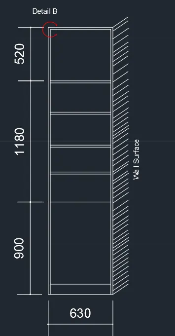
result shown in fig
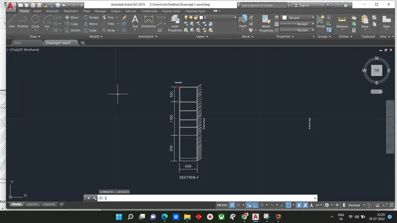
STEP-6: Creating Section -2 Elevation
Type Rec or rectangle
- Specify First corner point: Select any point on grid
- Specify other corner point or [Area:dimension:Rotation] : Click on dimension
- Length 3650
- Width 2600
Type 'o'
- Specify offset distance: Type 20 and enter
- Select object to offset: Select rectangle drawn earlier and select inside of rec
- Select both rec and explode
Type 'o'
- Specify offset distance distance: 100 annd press enter
- Select object to offset bottom edge of outer rectangle and click on top
Type 'o'
- Specify offset distance: type 800
- Select object from bottom edge of outer line and click on top
Type 'o'
- Specify offset distance: Type 500 and press enter
- Select object to offset at top edge of inner rectangle and click on bottom
Thickness offset 20 for both lines
Trim off extra line
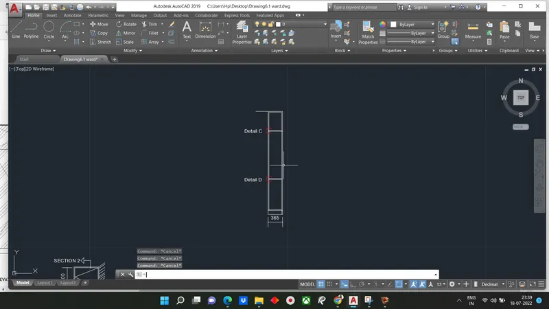
STEP -7: creating Layer
Go to layer option Created layer as per over requirement by clicking to new layer and remae it to ex: Walls
Allot layer as per created
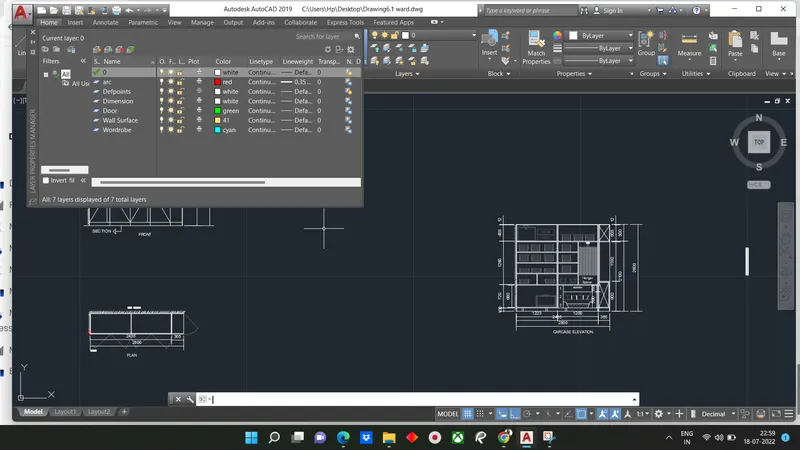
Result:
The result of given question is to be solve it consiste of plan view,Front elevation, carcase elevation and side elevation With 2 Section views.
The component in drawing for wardrob are drawn randomly not upto scale
Assign particular layer to each and different part of Drawing
All dimension are in mm
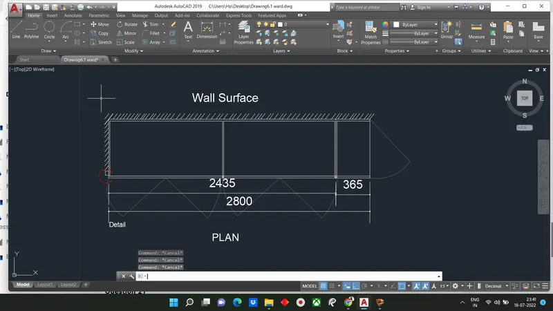
Question 2)
Answer:
Aim: To create the floor plan as shown in figure
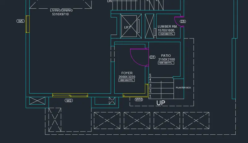
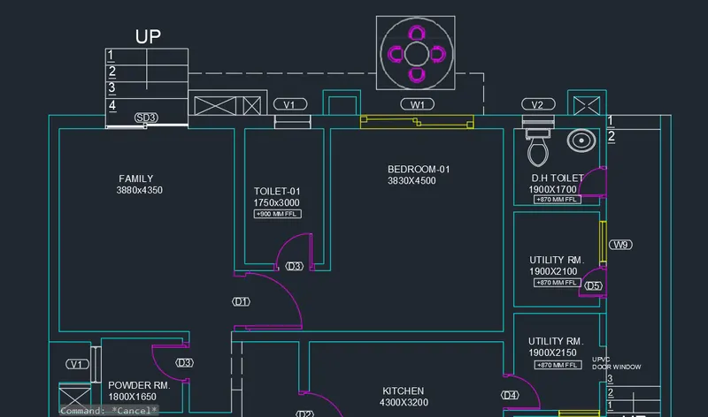
Introduction: Floor plan given is of duplex house with one bedroom in ground floor with one bedroom in ground floor with kitchen, sit out, living room, stairs, furniture, foyer, utility room, family sit out, D.H. toielt etc. in the ground floor.Ouer aim is to create the floor plan without furniture.
The wall thickness of inner and outer walls is given and dimensions of steps.
The size of windows and door are assumed as:
Door 1 or D1: 1200mm x 2200 mm
D2: 1000mm x 2100mm
D3: 900mm x 2100mm
D4: 800mm x 2100mm
D5: 700mm x 2100mm
Slide Door: 2300mm x 2100mm
W1: 2500mm x 1500mm
W2: 2300mm x 1500mm
W3: 1000mm x 1500mm
W5: 1100mm x 1500mm
W9: 900mm x 1500mm
Window 10 is a box glass opening
V1: 800mm x 500mm
V2: 700mm x 500mm
Procedure:
Open Autocad
In startup setting start from scratch select metric(meter)
Open grid and snap settings
Type UN in command box and press enter
Change Units Type to decimal and precision to 0.00 and insertion scale to milimeters
STEP-1: Creating family sit out bedroom-1
Type XLine in command box and press enter
- Specify a point or [Hor: Ver: Ang: Bisect:Offset]: Click on hor and select any point on the screen
Type XLine in command box and press enter
- Specify a point or[Hor: Ver: Ang: Bisect: Offset]: Click on ver and select any point on the horizontal Xline
TYpe'o' or offset and press enter
- Specify offset distance: Type 0.23 and press enter
- Select object to offset: Select horizontal XLine and click on bottom
- Select object to offset: Select vertical XLine and click on right
Type 'o'
- Specify offset distance: Type 3.88 and press enter
- Select object to offset: Select the vertical Xline of wall thickness and click on right
Type 'o' or offset
- Specify offset distance: Type 0.23 and press enter
- Select object to offset: Select the last offset to give wall thickness and click on right
Type 'o' or offset
- Specify offset distance: Type 1.75and press enter
- Select object to offset:Select the last vertical offset line and click on right
Type 'o' or offset
- Specify offset distance: Type 0.15 and press enter
- Select object to offset: Select the last offset to give wall thickness and click on right
Type 'o' or offset
- Specify offset distance: Type 3.83 and press enter
- select object to offset: Select the last vertical offset line and click on right
Type 'o' or offset
- Specify offset distance: Type 0.23 and press enter
- Select object to offset: Select last offset to give wall thickness and click on right
Type 'o' or offset
- Specify offset distance: Type 1.9 and press enter
- Select object to offset: Select the last vertical offset line and click on right
Type 'o' or offset
- Specify offset distance: Type 0.15 and press enter
- Select object to offset: Select the last offset line to give wall thickness and click on bottom
Type 'o' or offset
- Specify offset distance: Type 4.35 and press enter
- Select object to offset: Select the horizontal offset XLine of wall thickness and click on bottom
Type 'o' or offset
- Specify offsdet distance: Type 0.23 and press enter
- Select object to offset: Select last offset line to give wall thickness and click on bottom
Trim off outer portion of XLines
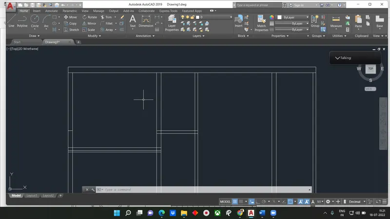
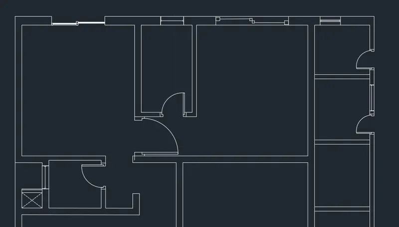
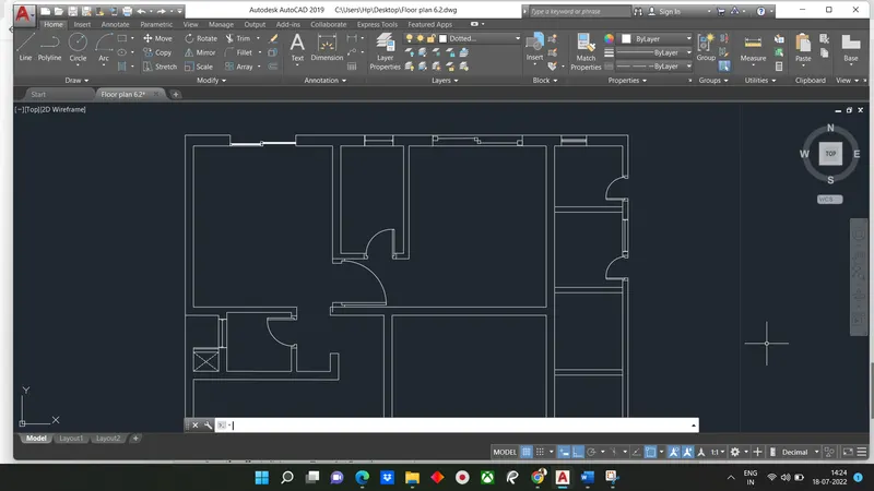
The results of first after creating window and door openings for family sit out and bedroom 1, toilet and utility room is as follow
STEP-2: Creating Living, foyer,patio
Type 'o' or offset
- Specify offset distance : Type 9.71 and press enter
- Select object to offset: Select the horizontal offset line of wall thickness at the powder room and click on bottom
Type 'o' or offset
- Specify offset distance: Type 0.23 and press enter
- Select object to offset: select last offset line to give wall thickness and click on bottom
Extend both lines to right edge XLIne
Type 'o' or offset
- Specify offset distance: Type 3.22 and press enter
- Select object to offset: Select the horizontal line at bottom and click on top
Type 'o' or offset
- Specify offset distance: Type 0.15 and press enter
- Select object to offset: Select last offset line to givea wall thickness and click on top
Type 'o'
- Specify offset distance: Type 0.23 and press enter
- Select object to object: Select last offset line to give wall thickness and click on top
Type 'o'
- Specify offset distance: Type 1.6 and press enter
- Select object to offset: Select the last offset line and click on top
Type 'o'
- Specify offset distance: type 0.23 and press enter
- Select object to offset: Select last offset line to give wall thickness and clickon top
Trim off lines at the living/dining room as shown in figure
Trim off extra XLine at bottom
Using line command create a line at the center wall at the bottom foyer room
Type 'o' or offset
- Specify offset distance: Type 2 and press enter
- Select object to offset: Select the line drawn earlier and click on right
Type 'o' or offset
- Specify offset distance: Type 0.23 and press enter
- Select object to offset: Select last offset line to give wall thickness and click on right
Type 'o' or offset
- Specify offset distance: Type 2.15 and press enter
- Select object to offset: Select the last offset line drawn earlier and click on right
Type 'o' or offset
- Specify offset distance: Type 0.15 and press enter
- Select object to offset: Select last offset line to give wall thickness and click on right
Type 'o' or offset
- Specify offset distance: Type 2.1 and press enter
- Select object to offset: Select the top edge of foyer room and click on bottom
Type 'o' or offset
- Specify offset distance: Tyoe 0.15 and press enter
- Select object to offser: Select last offset line to give wall thickness and click on bottom
Trim off extra portions of lines as per the drawing
Draw a line at the right angle of lumber room
Type 'o' or offset and press enter or click offset from the modify tool bar
- Specify offset distance: Type 1.57 and press enter
- Select object to offset: select the last line drawn earlier and click onleft
Type 'o' or offset
- Specify offset distance: Type 0.15 and press enter
- Select object to offset: Select last offset line ti give wall thickness and click on left
Select the line command and draw a line just left of lumber room left wall edge
Create a wal thickness offset of 0.23 to the left
Create the lift room as shown in figure
Create cross line in lift and up using line command
Result is shown in fig
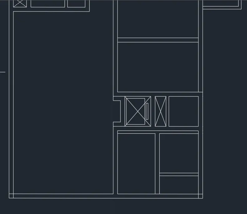
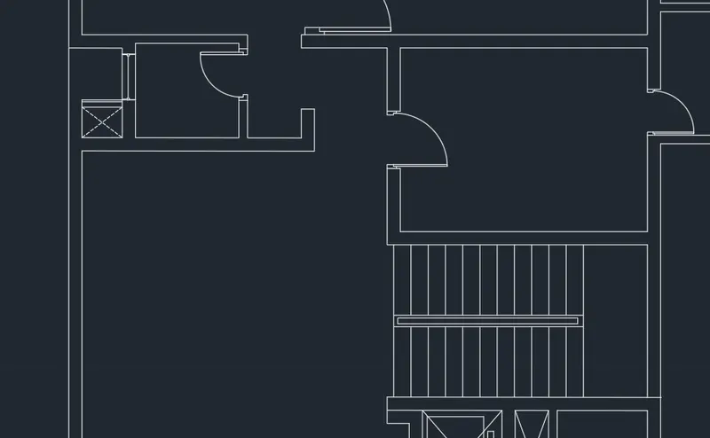
STEP-3: Creating Kitchen, Dining and stairs
Type 'o' or offset
- Specify offset distance: Type 4.35 and press enter
- Select object to offset: Select the bottom outer wall edge of bedroom 1
Type 'o'
- Specify offset distance: Type 0.23 and press enter
- Select object to offset: Select the Last offset line to give wall thickness and click bottom
Type 'o'
- Specify offset distance: Type 4.3 and enter
- Select object to offset: Select right inner wall Xline and click on left
Type 'o' or offset
- Specify offset distance: Type 0.23 and press enter
- Select object to offset: Select last offset line give wall thickness and click on left
Trim off extra portion of edge
Draw a line connecting lift wall edge and kitchen bottom left corner
Type 'o' or offset
- Specify offset distance: Type 0.3 and press enter
- Select object to offset: Select last line drawn earlier and click on right
- Select object to offset: Select last line drawn earlier and click on right
- Select object to offset: Select last line drawn earlier and click on right
- Select object to offset: Select last line drawn earlier and click on right
- Select object to offset: Select last line drawn earlier and click on right
- Select object to offset: Select last line drawn earlier and click on right
- Select object to offset: Select last line drawn earlier and click on right
- Select object to offset: Select last line drawn earlier and click on right
- Select object to offset: Select last line drawn earlier and click on right
- Select object to offset: Select last line drawn earlier and click on right
Draw the hand rails and trim of extra portion of stair
Create door openings and window openings in the walls using line and offset command
Create open area box and cross lines at the dinning area upto the edge of the stairs
STEP-4: Creating outdoor seating canopy
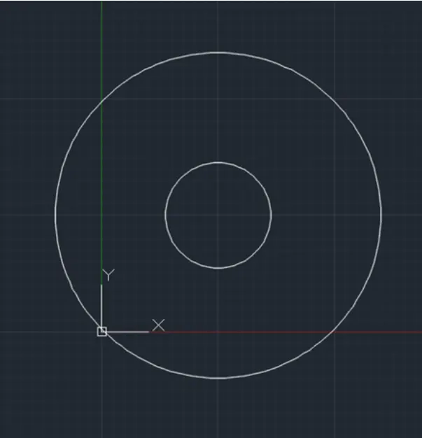
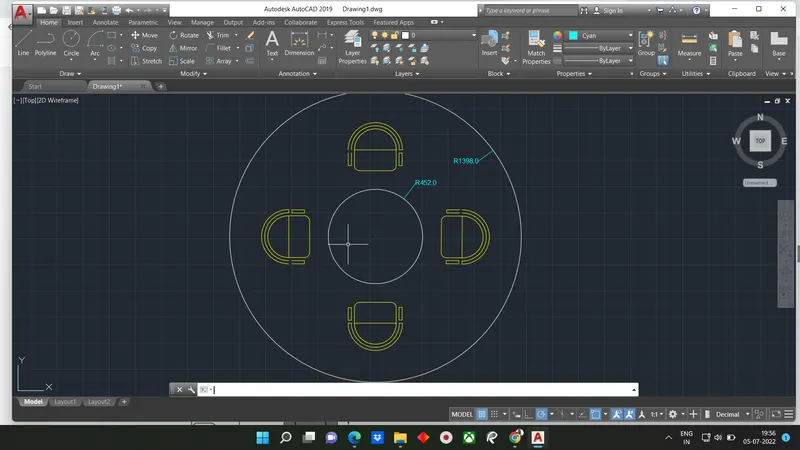
Type'c' or Circle
- Specify center point for circle: Type 10,10 and press enter
- Specify radius of circle or diameter: Type 4.52
Type 'C'
- Specify center point for circle:Type 10,10 and press enter
- Specify raius of circle or diameter: Type 13.98 and press enter
Type 'C'
- Specify center point of circle: Type 20,20 and enter
- Specify radius of circle or diameter: Type 2 and enter
Type 'C'
- Specify center point for circle: 20,20 and enter
- Specify radius of circle or diameter: Type 2,3 and press enter
Type 'c'
- Specify center pointfor circle: Type20,20 and press enter
- Specify radius of circle or diameter: Type 2,8 and press enter
Type L or line
- Specify first point: Turn on osnap and select left end of circles drawn
- Specify Next point: Turn on oSNAP and select the right end of circles drawn
Type Tr or trim
- Select object: Press enter to select all the object
- Trimn: Trim bottom part of circle
Type Rec
- Specify first corner point: Turn on OSNAP and select left edge of semi circle
- Specify other corner point: Turn on oSNAP and keep cursor edge next to last point andstart polar tracking down and type 2 and enter
Type Co or copy command
- Select object: Select rectangle drawn previously
- Specify base point: Select bottom right corner of the rectangle
TYpe rec
- Specify first corner point: Turn oSNAP select left edge of inner most semi circle
- Specify other corner point: Turn on OSNAP and keep curser onedge next to lastpoint and start polar tracking down and type 3 and press enter
TypeL or Line
Trim extra portion
Type 'co' or copy command
- Select entire chair
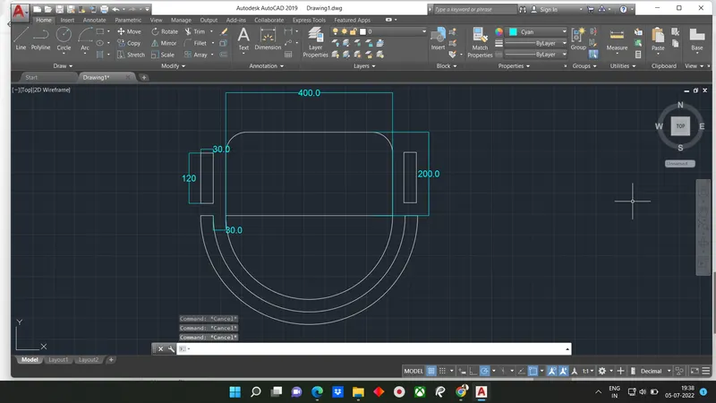
Type AR
- SElect object : Select chair drawn
STEP-5: Creating House Components
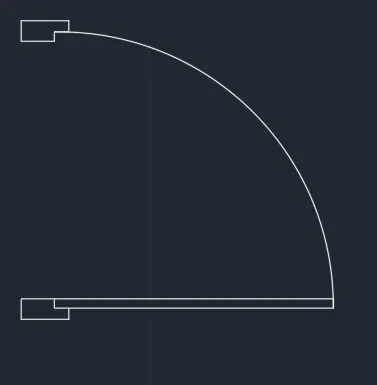
Door D1:
- Use line command to create shape of door
- Use Rec command with dimension 0.1m x2.1m
- Use start center ens type arc from tool bar
- Use same procedure to create other doors
- Result is created
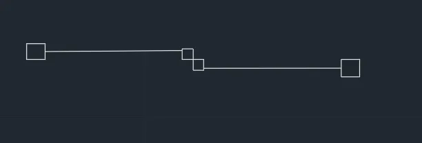
Sliding Door SD
- Sliding door is created using line and rectangles with dimension 2300mm x2100mm
- Result of Sliding door is created
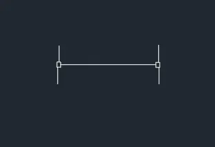
Window W1
- Window created as per size/dimension assumed by using line and rec tool
- Window is created
We create all Ventilator, doors and window as per size
STEP-6: Creating Layer
- Open layer and create it as per required
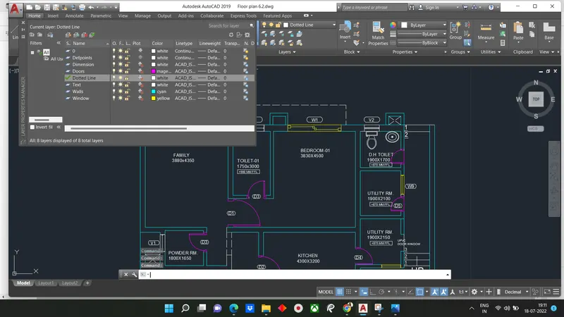
RESULT:
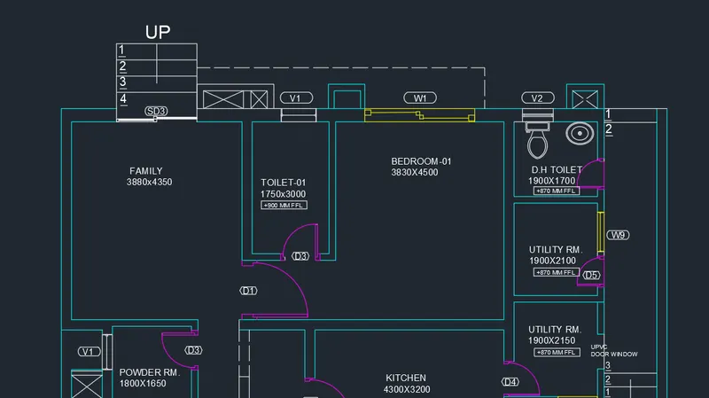
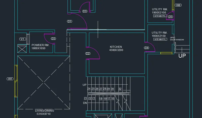
Floor plan is created without furniture it is mention in question, result shows different door, window, along with ventilators, walls.
Text is placed where ever it is given.
All dimension are in mm
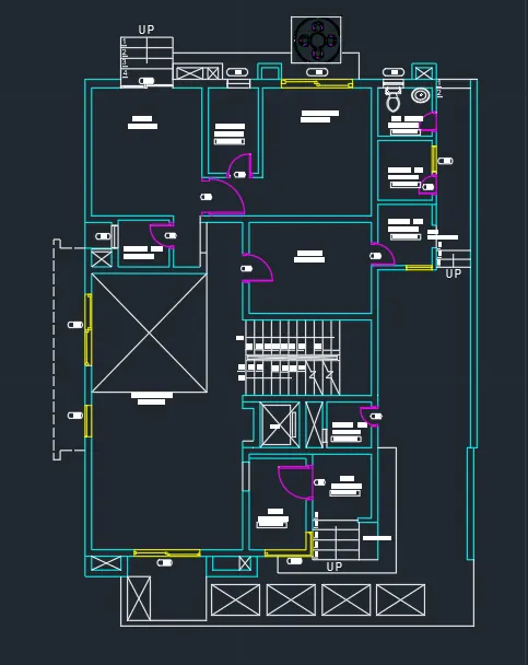
1. Family room, toilet and bedroom
2. Kitchen, powder rm, utility room and stairs
3. Living , foyer, lumber rm, patio
Question 4)
Answer:
Aim: To create column schedule as shown in figure
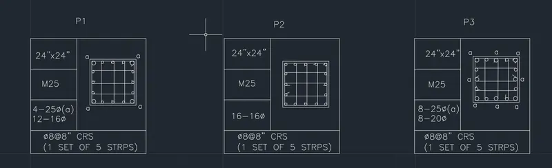
Introduction: The figure given above has three column schedules P1 to P3. The difference between all the schedules is that the diameter of bars used in them.
All the columns are with 16 no. of bars M25 grade concrete is used in all the columns.Stirrups used used are also in same number. The dimension of each column is 24"x24"
Procedure:
Open Autocad
In startup settings start from scratch select imperial (feet ad inches)
Open grid and snap setting and do as per required
Type UN in command tab press enter
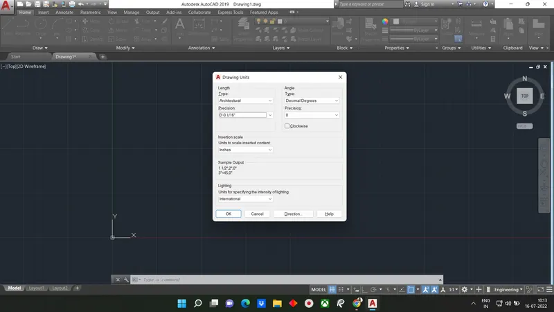
Change units type to architectural
STEP-1: Creating Table Using Lines
Type 'rec' or rectanglein the command box or select rectangle from the draw toolbar
- Specify first corner point: Select any point on the grid
- Specify other corner pount or (Area: Dimension: Rotation): Click on dimension
- Specifybar
- length for rectangle: Type 60" and press enter
- Specify width for rectangle: Type 60" and press enter and set the direction as first quadrant
- Type explode and select the rectangle created
Type 'o' or offset and press enter or click offset from the modify tool bar
- Specify offset distance: Type 2' and press enter
- Select object to offset : Select the left edge of rectangle and select on right.
Type 'o' or offset and press enter or click offset from the modify tool
- Specify offset distance: Type 1' and press enter
- Select object to offset: Select the bottom edge of the rectangle and select on top
Create a line from the top left corner of the rectangle to the lleft end of bottom offset line of 1'
Divide the line into 3 segments and set mode as 3
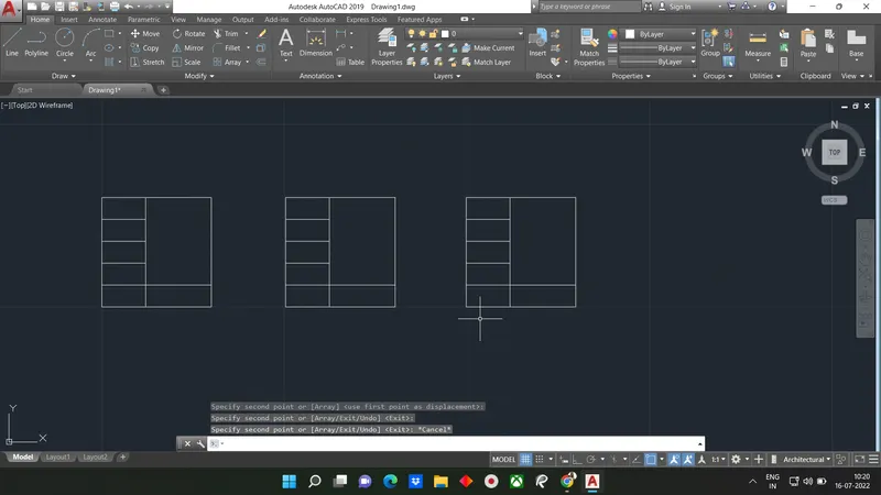
Draw line using line command to next offset line at 2' away
Copy the entire figure drawn and paste it two more times to complete drawing tables for data
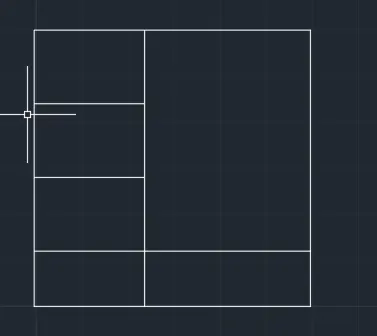
Result shown in screenshot
STEP-2: Creating Column Section
P1 Column
Type rec in command box or we can select rectangle from draw toolbar
- Specify first corner point: Select ny point on the grid
- Specify other corner point or(Area: Dimension: Rotation) Click on dimensions.
- Specify length for rectangle: Type 24" and press enter
- Specify width for rectangle: Type 24" and press enter and set the direction as first quadrant
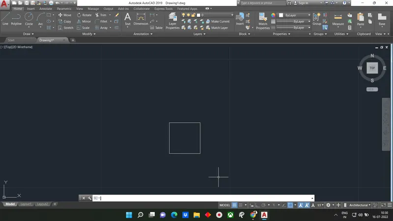
Type '0' and press enter or click offset from the modify tool bar
- Specify offset distance: Type 1"and press enter
- Select object to offset: Select the rectangle drawn earlier and select the inside of the rectangle
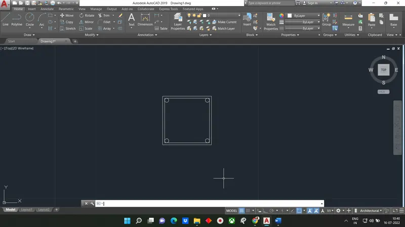 Create the same circles at all four corners
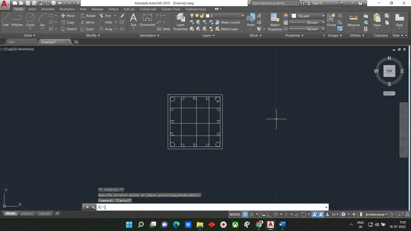
Divide the all the four-sides using Divide command into 4 segments each
Type 'c' or circlein command box
- Specify center point for circle[3P:2P: Ttr(tan tan rad)]:2P
- Specify first end point of circle diameter: Select the points created from dividing the rectangle
- Specify second end point of circle daimeter: Type 0.62" (16mm dia) and press enter
Create similar circle at all points
Copy the circle to all the points created above as all the bars are of same radius
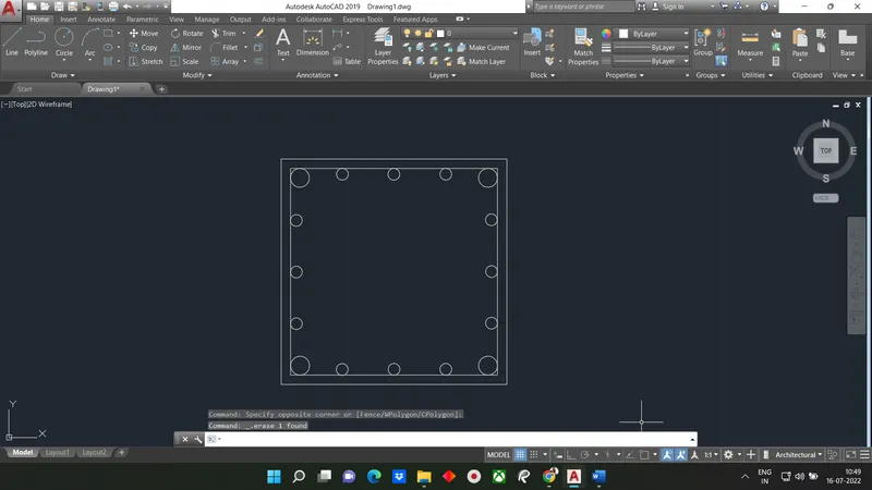
Stirrups bars are drawn using line command from one end of 16mm dia reinforcement to the other
Additional bar folding's are also drawn using line command
P2 Column
Type 'rec' or rectangle in the command box or select rectangle from the draw toolbar
- Specify first corner point: Select any point on the grid
- Specify other corner point or[Area: Dimension: Rotation]: Click on dimensions
- Specify length for rectangle: Type 24" and press enter
- Specify width for rectangle:Type 24" and press enter and set the direction as first quadrant
Type 'o' and press enter or click offset from the modify tool bar
- Specify offset distance: Type 1" and press enter
- Select object to offset : Select the rectangle drawn earlier and select the inside of rectangle
Type C or circle in the command box or select circle from the draw toolbar
- Specify center point for circle [3P:2P:Ttrn(Tan Tan Rad)]: Select Tr
- Specify point an object for first tangent of circle: Select the left edge of the inner rectangle
- Specify point on object for second tangent of circle: Select the bottom edge of the inner rectangle
- Specify radius of the circle: Type 0.62" (16mm dia and 8mm radius bars)and press enter
Create the same circles at all four corners
Divide the all the four-sides using DIVIDE command into segments each
Copy the circle to all the points created above as all bars are of same radius 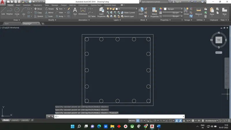
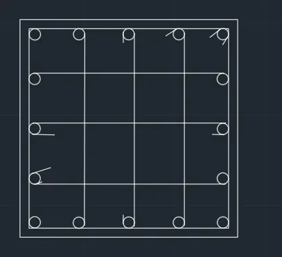
Stirrups bars are drawn using line command
Additional bar folding's are also drawn using line command
P3 Column
Type 'rec' or rectangle in the command box or select rectangle from the draw tool
- specify first corner point: select any point on grid
- Specify other corner point or [Area: Dimesion: Rotation]: Click on dimensions
- Specify length for rectangle: Type 24 " and press enter
- Specify width for rectangle : Type 24" and press enter and set direction as first quadrant
Type '0' and press enter or click offset enter
- Specify offset distance: Type 1" and press enter
- Select object to offset: Select the rectangle drawn earlier and select the inside of the rectangle
Create the same circles at 'a' portion which is given in figure
Using copy command and OSNAP copy the circle selecting quadrant end and paste it the midpoint of each side
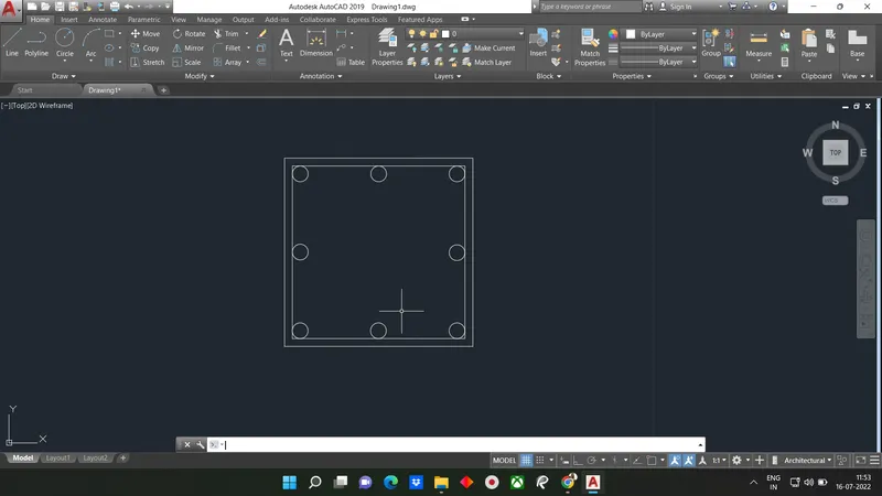
Type 'C' or circle in the command box or select circle from the draw toolbar
- Specify center point for circle[3P:2P:Ttr(Tan Tan Rad)]: 2P
- Specify first end point of circles diameter: Select the points created from dividing the rectangle
- Specify second end point of circles diameter: Type 0.7874""(20mmdia bras)and press enter
Create similar circles at all point created
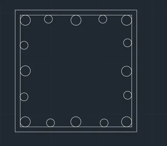
Stirrups bars are drawn using line command from one end of 20mm and 25mm dia reinforcement to the other at the middle
Additional bar folding's are also drawn using line command
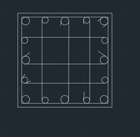
STEP-3: Adding Text
Go to annotation tab in ribbon tab and click on arrow at the below to open the text properties in dialogue box click on new style
- Set style name to new
- Change font name to
- Change height to
- Click on set current and apply and close
Type text in command box and press enter
- Specify start point of the text: select inside the first box at the start point
- specify rotation angle of text: Type 0 degree press enter
- Now the type 24"x24" in the first line and press esc
Follow the same procedure to all the horizontal text
Type mtext in command box and press enter
- Specify start point of the text : select inside the 3rd box at the start point
- Specify rotationangle of text: Type 90 degree press enter
- Now the type 4-25dia press enter and type 12-16 dia in second line and press esc
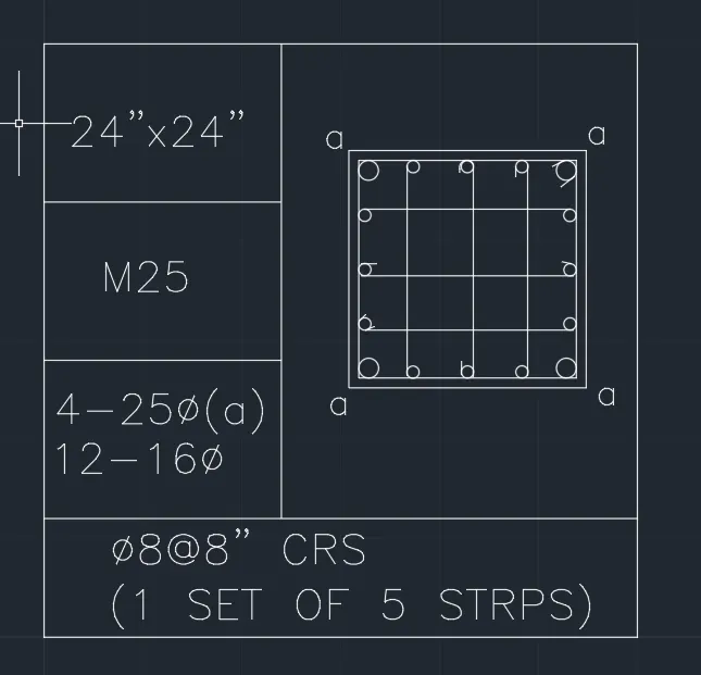
Follow same procedure to all multi text
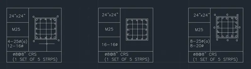
RESULT:
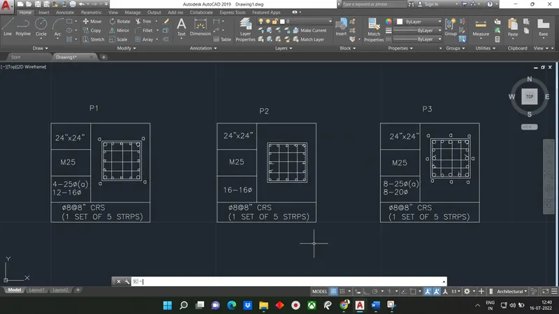
The result of the given challenge question is shown as below.
Challege consists of three column schedules which are created using circles and rectangles.Square columns of size 24"shown with stirrups,main reinforcement and secondary reinforcement.
All dimension are mentioned in feet & inches
Text use Romans
Question 3)
Answer:
Aim: To create the kitchen layout plans as shown in figure
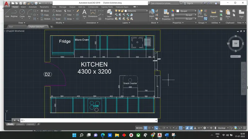
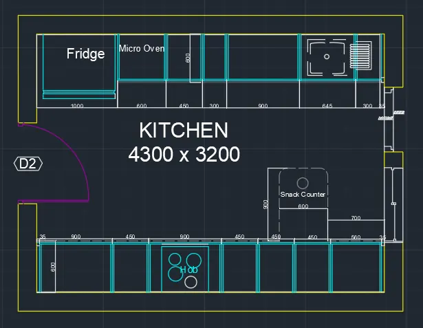
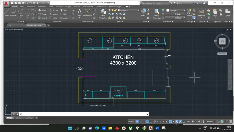
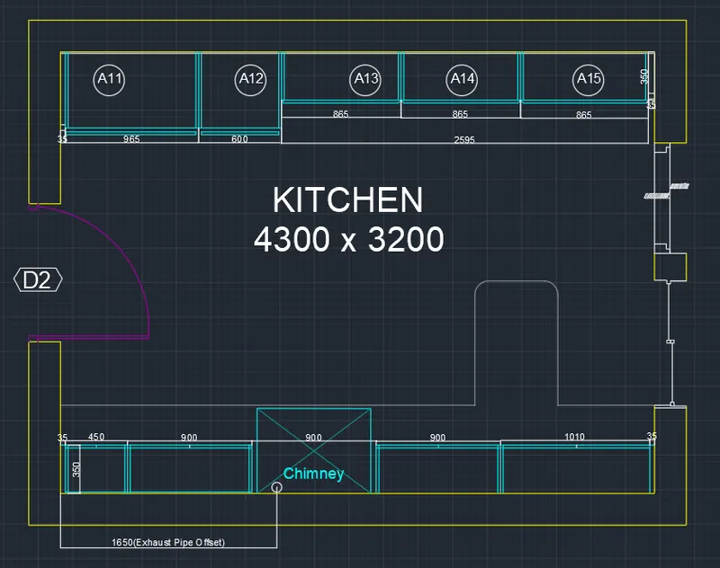
Introduction: Two kitchen plans are given one below contour plan and another above contour plan. Below contour plan consists of fridge, micro oven, cup boards, hob, dishwasher etc.Above contour plan consists of cupboards, chimneys etc.
Procedure:
Open Autocad
In startup Setting start from scratch select(Meter)
Open grid and snap setting
Change snap and grid spacing to 0.1
Change major line every grid grid line to 10
Turnoff adaptive grid
Type 'UN' in command box and press enter
Change units type to decimal and precision to 0.00 and insertion scale to milimeter
STEP-1: Creating Below Contour Plan
Type 'rec' or rectangle in the cammond tab or we can select directly from toolbar
- Specify first corner point: Select any point on grid
- Specify other corner point or [Area:Dimension:Rotation]: D
- Specify length for rectangle: Type 4300 and press enter
- Specify width for rectangle: Type 3200 and press enter and set the directionas first quadrant
Type '0'or offset and press enter or click offset from the modify toolbar
- Specify offset distance: Type 230 and press enter
- Select object to offset: Select the rectangle drawn earlier and select the outside of the rectangle
Explode two rectangle using explode command
cReate a door opening using line and trim command
Type 'o' or offset and press enter
- Specify offset distance: Type 600 and press enter
- Select object to offset: Select the bottom edge of the inner rectangle and select on top
Type 'o' or offset and press enter
- Specify offset distance: Type 40 and press enter
- Select object to offset: Select the last offset line and click on bottom
Draw a line starting from left end of the last offset line and bottom left corner of the inner rectangle
Type 'o' or offset
- Specify offset distance: Type 35 and press enter
- Select object to offset: Select the line drawn earlier and click on right
Type 'o' or offset
- Specify offset distance: Type 900 and press enter
- Select object to offset: Select the line drawn earlier and click on right
Type 'o' or offset
- Specify offset distance: type 450 and press enter
- Select object to offset: Select the last offset line and click on right
- Select object to offset: Select the last offset line and click on right
- Select object to offset: Select the last offset line and click on right
Type 'o' or offset
- Specify offset distance: Type 630 and press enter
- Select object to offset: Select the last offset line and click on right
Type 'o' or offset
- Specify offset distance: Type 10 and press enter
- Select object to offset: Select the bottom edge of the inner rectangle and selecton top
Type 'o' or offset
- Specify offset distance: Type 20 and press enter
- Select object to offset: Select the line offset at 35 from left and click on right
Repeat the same process for all the offset lines drawn above
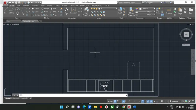
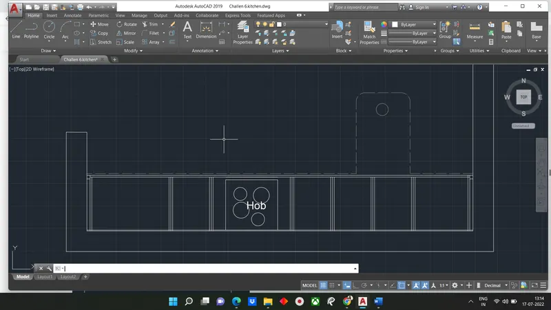
Create hob using rectangle and circle command
Create the snack counter using line command and ISO dash space as line type with line type scale as 0.1 and use fillet option at top corners.
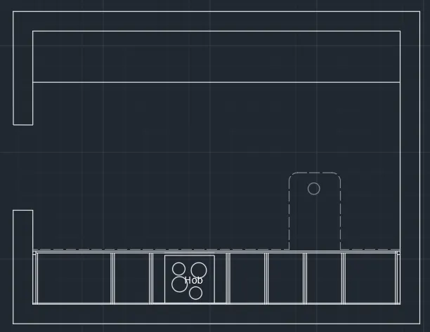
Type 'o' offset
- Specify offset distance: Type 600 and press enter
- Select object to offset: Select the top edge of the inner rectangle and select on bottom
Type 'o' offset
- Specify offset distance: Type 1000 and press enter
- Select object to offset: Select the door side line to make offset
Type 'o' offset
- Specify offset distance: Type 10 and press enter
- Select object to offset: Select the top edge of the inner rectangle and select on bottom
Draw a line starting from left end of the last offset line and bottom left corner of the inner rectangle
Type 'o' or offset and press enter or click offset from modify tool bar
- Specify offset distance: Type 35 and press enter
- Select object to offset: Select the line drawn earlier and click on left
Type 'o' or offset
- Specify offset distance: Type 300 and press enter
- Select object to offset: Select the last offset line and click on left
Type 'o' or offset
- Specify offset distance: Type 645 and press enter
- Select object to offset: Select the last offsetline and click on left
Type 'o' or offset
- Specify offset distance: Type 900 and press enter
- Select object to offset: Select the last offset line and click on left
Type 'o' or offset
- specify offset distance: Type 300 and press enter
- Select object to offset: Select the last offset line and click on left
Type 'o' or offset
- Specify offset distance: Type 450 and press enter
- Select object to offset: Select the last offset line and click on left
Type 'o' or offset
- Specify offset distance: Type 600 and press enter
- Select object to offset: Select the last offset line and click on left
Create the fridge component using rectangle, 2 point circle and line command as shown in fig
Doors and windows are created as per the step 3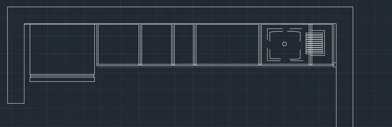
The result of step1 after adding doors and windows is as follows
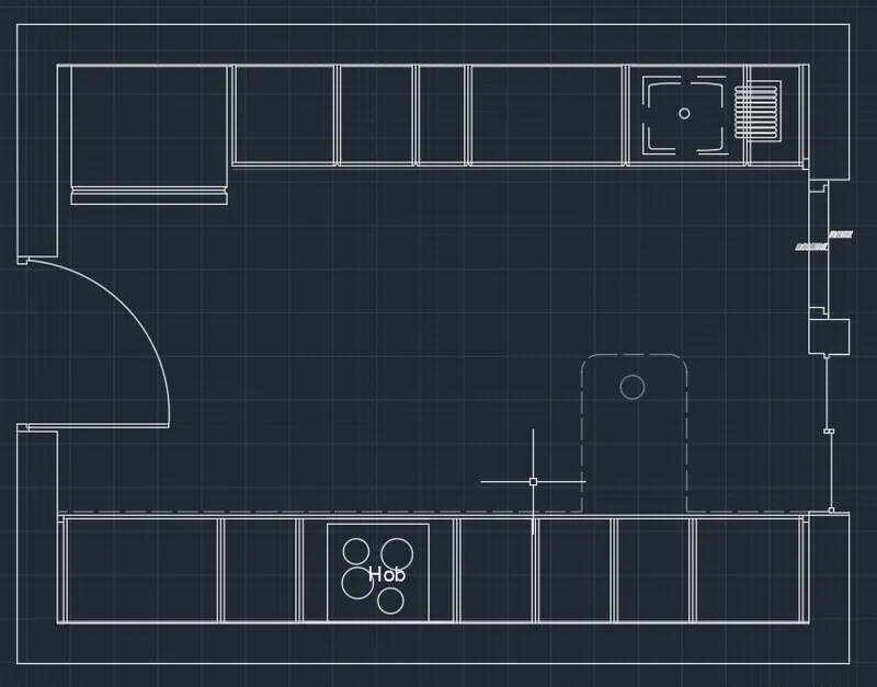
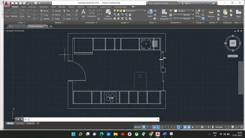
STEP-2: Creating Below Contour plan
Using copy command, copy all the necessary components of below contour pland and paste at any Point as walls, doors and window
Type 'o' or Offset and press enter or click offset from the modify toolbar
- Using copy command, copy all the necessary components of below contour plan and paste at any point such as walls, doors and window
Type 'o' or offset and press enter
- Specify offset distance: Type 350 and press enter
- Select object to offset: Select the bottom edge of the inner rectangle and select on top
Draw a line starting from left end of the last offset line and bottom left corner of inner rectangle
Type 'o' or offset
- Specify offset distance: Type 35 and press enter
- Select object to offset: Select the line drawn earlier and click on right
Type 'o' or offset
- Specify offset distance: Type 450 and press enter
- Select object to offset: Select the last offset line and click on right
Type 'o' or offset
- Specify offset distance: Type 900 and press enter
- Select object to offset: Select the last offset line and click on right
- Select object to offset: Select the last offset line and click on right
- Select object to offset: Select the last offset line and click on right
Type'o' or offset
- Specify offset distance: Type 1010 and press enter
- select object to offset: Select the last offset line and click left
Type 'o' or offset
- Specify offset distance: Type 10 and press enter
- Select object to offset: Select the last offset line and click on left
Type 'o' or offset
- Specify offset distance: Type 20 and press enter
- select object to offset: Select the line offset at 35 from left and click on right
Repeat the same for all offset lines drawn
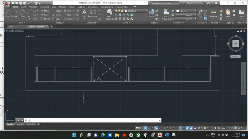
Create the chimney in the 0.9 distance gap using a rectangle command
Create the snack counter using line command and ISO dash as line type with line type scale as 0.1
Type 'o' or offset
- Specify offset distance: Type 600 and press enter
- Select object to offset: Select the top edge of inner rectangle and select on bottom
Type 'o'or offset
- Specify offset distane: Type 350 and press enter
- Select object to offset: Select the top edge of the inner rectangle and select on bottom
Type 'o' or offset
- Specify offset distance: Type 10 and press enter
- Select object to offset: Select the top edge of inner rectangle and select bottom
Draw a line starting from left end of the last offsetnline and bottom left corner of the inner rectangle
Type 'o' or offset command
- Specify offset distance: Type 35 and press enter
- Select object to offset: Select the line drawn earlier and click on right
Type 'o' or offset command
- Specify offset distance: Type 965 and press enter
- Specify object to offset: Select the line drawn earlier and click on right
Type 'o' or offset command
- Specify offset distance: Type 600 and press enter
- Select object to other: Select the last offset line and click on right
Draw a line starting from left end of last offset line and bottom left corner of the inner rectangle of 0.35 distance
Type 'o' or offset command
- Specify offset distance: 865 and press enter (for 3 times)
- Select object to offset: Select the line drawn earlier and click on right
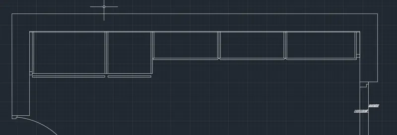
Doors and windows are created as per the step 3
Trim off extra portions
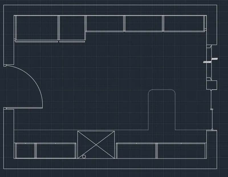
The result of step 2 after adding doors and windows is as follows
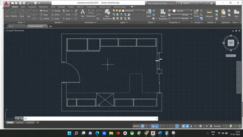
STEP-3: To create Door And Window
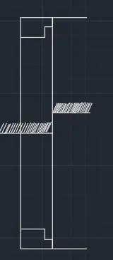
D3-
- Select line command and select outer end of door opening
- Draw a line of distance 80 and keep the curser to the right and draw a line of 50
- Keep thec curser to down and draw a line of 60 and keep the curser to right and draw aline of 50 and draw a line perpendicular to bottom end
- Mirror the same created and paste it on other side of door end
- Draw a line connecting the top edges of boot the shapes
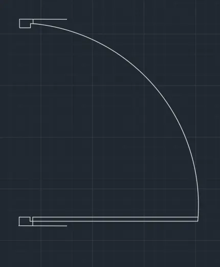
D2-
- Select the command and select the outer end of the door opening
- Draw a line of distance 0.08 and keep the curser to the right and draw a line of 50 and draw a line perpendicular to bottom end
- Mirror the same created and paste it on the other side of door
Type rec or rectangle in the command box or select rectangle from the draw toolbar
- Specify first corner point: Select any point on grid
- Specify other corner point or [Area:Dimesion:Rotation]: Click on dimensions
- Specify length for rectangle: Type 800 and press enter
- Specify width for rectangle: Type 60 and press enter and set the direction as first quadrant
Select start center end command from the drop down of arc tool from draw tool bar
- Select the start point: Select right edge of the shape drawn
- Select the centerpoint: Select the bottom of rectangle drawn
- Select the end point: Select the bottom end of the shape drawn at the other door end
Window 1
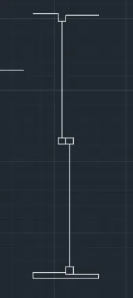
- Using rectangle command draw 2 rectangles at the center of the window
- Using line command draw 2 line from the midpoint of 2 rectangles to the opposite edges of window
- At the point of intersection of these lines draw 2 rectangles on both edges as shown in figure
STEP-4: Creating layers
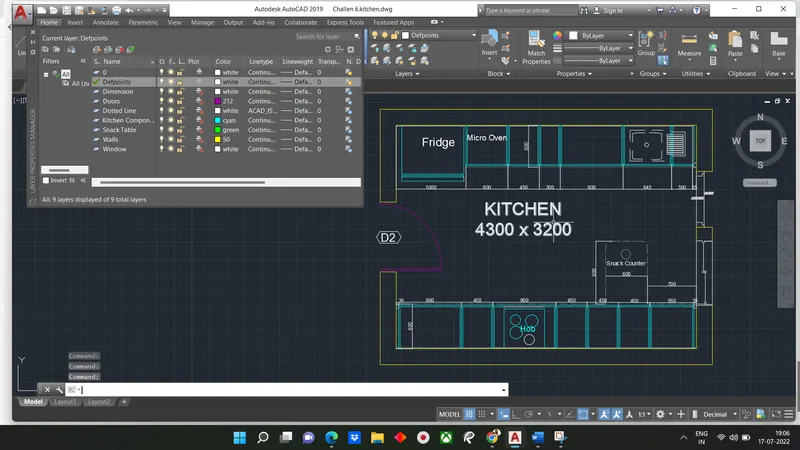
Open layer properties and create new layers by clicking on new layer or right click on any layer and select new layer to create new layer
Layer is created
Result:
The result of this challenge question consists two kitchen layouts. One below the contour plan and another above the contour plan.The wall thickness is assumed to be 230mm
The components of kitchen is created as per given in figure
Doors and window created with assumed dimension because it is not given with question
All dimension are in mm
A) Below Counter Plan
B) Above Counter Plan
Question 5)
Answer:
Aim: To create raft foundation as shown in given challenge drawing
Introduction:
Procedure:
Open Autocad
In startup settings start from scratch select imperial (feet and inches)
open grid and snap setting
Change snap and grip spacing to 1'
Change major line every grid line to 10'
Turnoff adaptive grid
Type 'un' in command box and press enter
Change Units type to architectural and precision to 1'1/16"
STEP-1: Creating Center lines
- Change line type to center in properties tool bar
- change line type scale to 25 in this case
Type XL or xline in command box and press enter
- Specify a point or[Hor:Ver:Ang:Bisect:Offset] : Click on ver
- Specify through point: Select any point on the screen
Type 'o' and press enter or click offset from the modify tool bar
- Specify offset distance: Type 5'9" and press enter
- Select object to offset: Select the first XLine drawn and click on right
- Press enter twice
- Specify offset distance: Type 2' and press enter
- Select object to offset: Select the last offset line drawn and click on right
- Press enter twice
- Specify offset distance: Type 7' and press enter
- Select object to offset: Select the last offset line drawn and click on right
- Press enter
- Specify offset distance: Type 4'6" and enter
- Select object to offset: select the last offset line drawn and click on right
- Press enter twice
- Specify Offset distance: Type 4' and press enter
- Select object to offset: Select the last offset line drawn and click on right
- Press enter
- Specify offset distance: Type 5'7.5" and press enter
- Select object to offset: Select the last offset line drawn and click on right
Type 'XL'or xline in command box and press enter
- Specify a point or[Hor:Ver:Ang:Bisect:Offset]: Click on Hor
- Specify through point: Select any point on the first vertical Xline
Type 'o' and press enter or click offset from the modify tool bar
- Specify offset distance: Type 5'7.5" and press enter
- Select object to offset: Select the hor Xline drawn and click on bottom
- Press enter
- Specify offset distance: Type 3'7.5" and press enter
- SElect object to offset: Select the last offset line drawn and click on bottom
- Press enter twice
- Specify offset distance: Type 4'9" and press enter
- Select object to offset: Select the last offset line drawn and click on bottom
- Press enter twice
- Specify offset distance: Type 5'10.5" and press enter
- Specify object to offset : Select the last offset line drawn and click on bottom
- Press enter twice
- Specify offset distance: Type 5'7.5" and press enter
- Specify object to offset: Select last offset line drawn and click on bottom
- Press enter Twice
- Specify offset distance: Type 3'9" and press enter
- Specify object to offset: select last line of object and click to bottom
- Press enter
- Specify offset distance: Type 5'9" and press enter
- Select object to offset : Select the last offset line drawn and click on bottom
- Press enter twice
- Specify offset distance: Type 13'10.5" and press enter
- Select object to offset: Select the last offset line drawn and click on bottom
- Press enter twice
- Specify offset distance: Type 10'4.5" and press enter
- Select object to offset: Select the last offset line drawn and click on bottom
- Press enter twice
- Create a rectangle around the intersecting line and trim off the extra portions
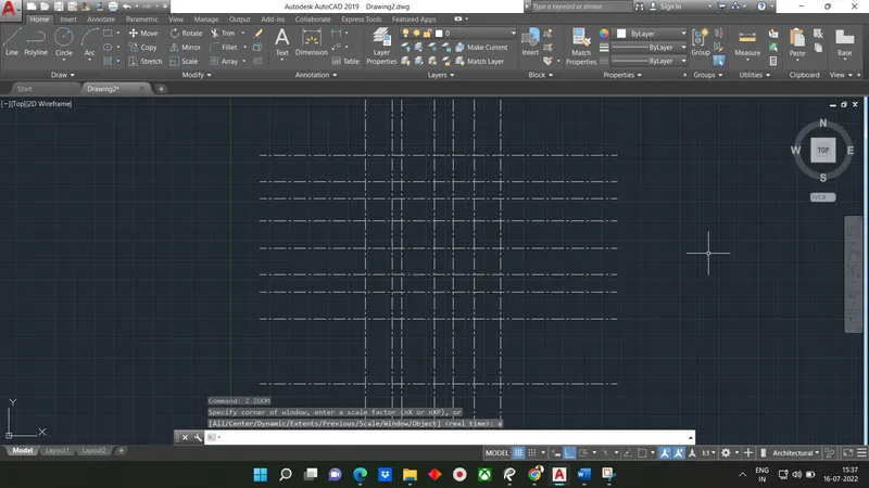
STEP-2: Creating walls and columns
Type 'L' or line in command box and press enter or select line command from the draw tool
- Specify first point: Select the bottom left corner
- Specify second point: Select the bottom left corner
Type 'o' or offset and press enter or click offset from the modify tool bar
- Specify offset distance: Type 4.5" and press enter
- Select object to offset: Select the line drawn earlier and click on right
1.Creating column 24"x24"and respective footing
Type 'L' or line in command box and press enter or select line command from the draw toolbar
- Specify first corner point: Select any point on grid
- Specify other corner point or (Area: Dimension: Rotation): Click on dimension
- Specify length for rectangle: Type 24" and press enter
- Specify width for rectangle: Type 24" and press enter and set the direction as fourth quadrant
Type 'o' or offset and press enter or click offset from the modify tool bar
- Specify offset distance: Type 3' and press enter
- Select object to offset: Select the rectangle drawn earlier
- Adjust the right edge so that the distance from column is 2'
- Trim all extra portions
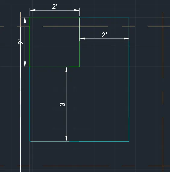
Follow similar procedure all the columns with sizes 24"x24"
2.Creating column 9"x24" and respective footing
Using point command create a point where column is required
Type rec or rectangle in command tab or we can select rectangle from draw toolbar
- Specify first corner point: Select point created
- Specify other corner point or [Area:Dimension:Rotation]: Click on dimension
- Specify length for rectangle: Type 24"or 9" and enter
- Specify width for rectangle: Type 9" or 24" and press enter and set the direction as respective quadrant
- Also create footing with the given spacing with respect to column
- Trim off extra portions using trim command (Trim Tr-double Enter)
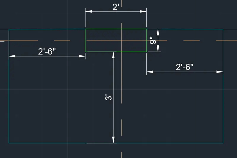
3. Creating Column 9"x18" and respective footing
Using point command create a point where the column is required
Type 'rec' or rectangle in the command box or select rectangle from the draw toolbar
- Specify first corner point: Select point created
- Specify other corner point or [Area: Dimension:Rotation]: Click on dimensions
- Specify length for rectangle: Type 18"or 9" and press enter
- Specify width for rectangle: Type 9" or 18" and press enter and set the direction as respective quadrant
- Also create footing with the given spacing with respect to column
- Trim off extra portions using trim command
- The result created below is two columns having same footing
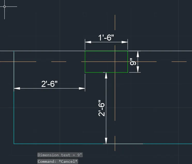
4. Creating Brick Wall at bottom
Using line command create brick wall of 9" in bottom side of plan as shown in fig
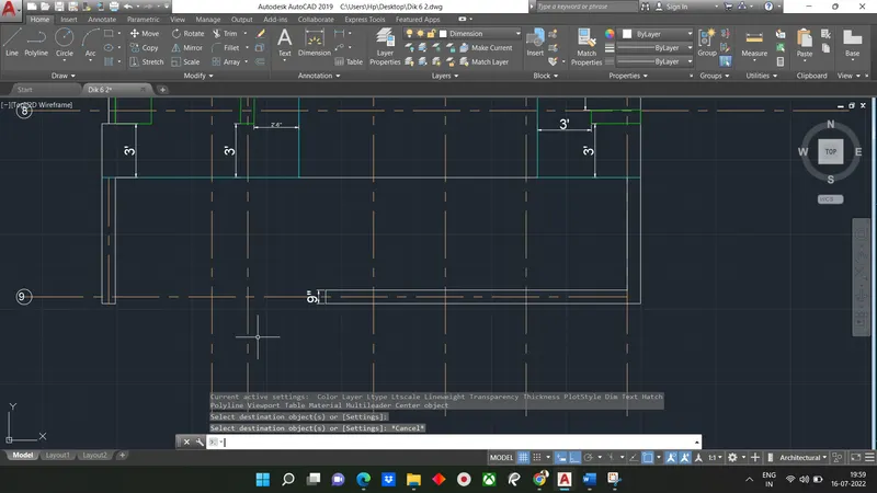
STEP-3: Creating layers and hatch
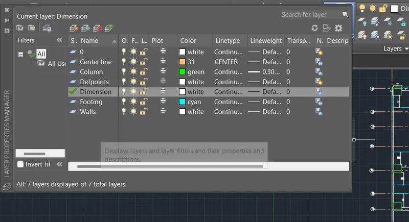
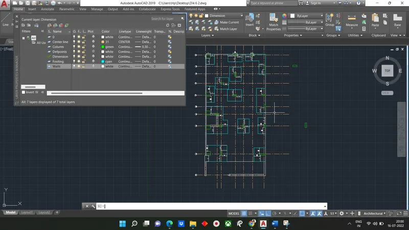
Open layer properties and create new layers by clicking on new layer or right click on any layer and select new layer to create new layer
Layer is created as shown in fig
Hatching
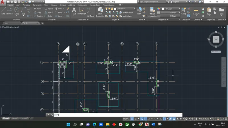
- For column create hatch type ANS137
- For brick wall create hatch type ANS132
- for R/w wall create hatch type AR-Conc
RESULT
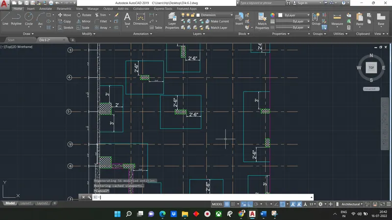
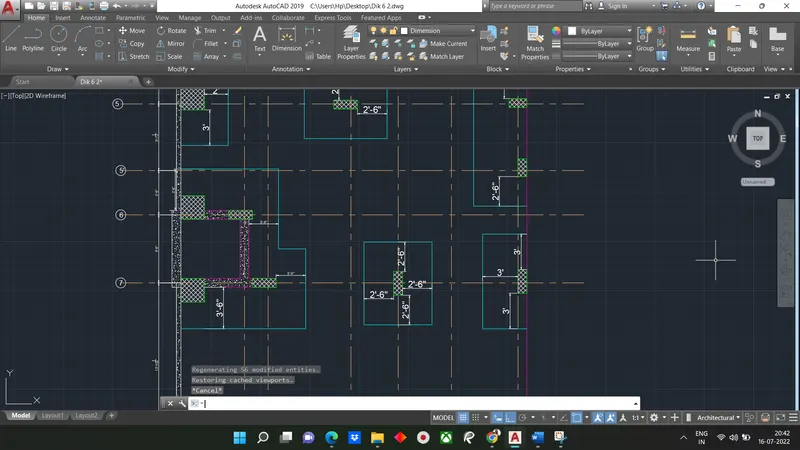
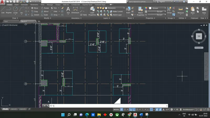
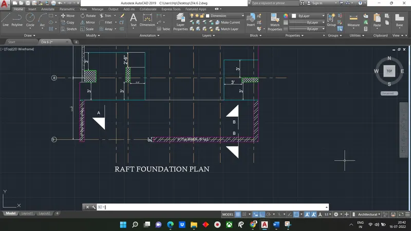
The result of challenge shows typical drawing of raft foundation plan with column dimensions and footing dimensions. Center lines are created using Center line type.
Column, R/wall and brick wall are hatched according.Different layers are created and assigned respectively.Column numbers are assigned starting from top left column as column or CL. Text is written where given in fig
All dimensions mentioned are in feet and inches
Dimensions and text are assigned using dimension layer and text layers
The column schedules after assigning layers to the respective components is as follow
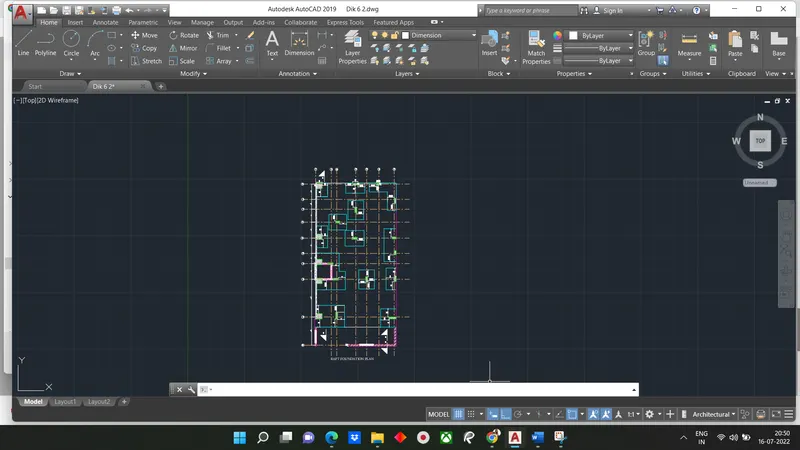
Not able to see proper dimension and drawing so i have attached pdf of layout