Creating a Wardrobe detailed drawing, Floor Plan, Kitchen Layout and Column Detail using AutoCad
1.
Aim: To draw the elevation and details of a wardrobe.
Introduction: To draw the elevation and details of a wardrobe and sketching with provided dimensions and text with use of layers.
Procedure:
- First we need to set the dimension to mm which is given in the drawing.
- Then understand the drawing from which point to start the drawing.
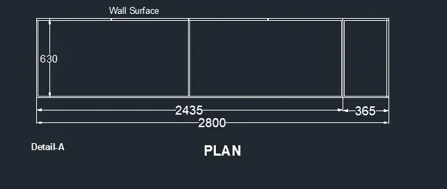
- Then first you need to draw the plan by using line command.
- After taking the dimensions, draw the plan by using line and offset command.
- You need to assume some dimension which are not given in the drawing as shown in the given drawing.
-
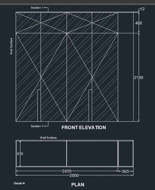
- After completing the first part, from the end points of the drawing, extend the lines to draw the front elevation.
- From that point as given the height of the drawing, extend the lines up to the given dimensions.
- Next extend the inner lines to the front elevation drawing with assuming some dimensions.
- Then by taking hatch command, Hatch the portion as given in the drawing.
- Take the dimension line and mention the dimensions as shown in the below drawing.
-
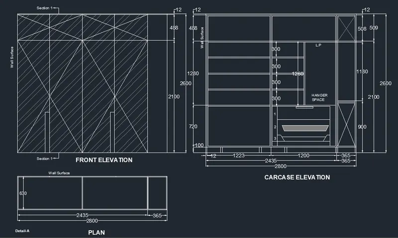
- From the Front elevaion part, extend the lines horizantally towards X-direction by using line command.
- Draw the outer lines by the given dimensions and assume the offset distance and do the offset to the outer lines.
- From that divide the inner lines with the given dimensions as shown in the drawing.
- Again take the offset to the inner lines by assuming offset distance.
- Then show the hanger portion and TV unit in the elevation part as shown in the draiwng.
- Finally give the dimensions as shown in the given drawing and this is carcase elevation.
-
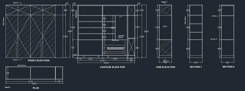
- After the carcase elevation, Extend the lines to the side elevation and draw the lines using line command.
- Then by using the same procedure draw the side elevation part using the line and offset command.
- Mention the dimensions as shown in the given drawing with proper alignment and hatching should be shown where ever required.
- From the side elevation, again extend the lines t draw the section portion which is given as section AA.
- For this section also use the same procedure by using given dimensios in the drawing.
- Draw the inner part of the section by using offset command.
- Finally show the clear dimension and final drawing is ready as shown in the result.
Result:
2.
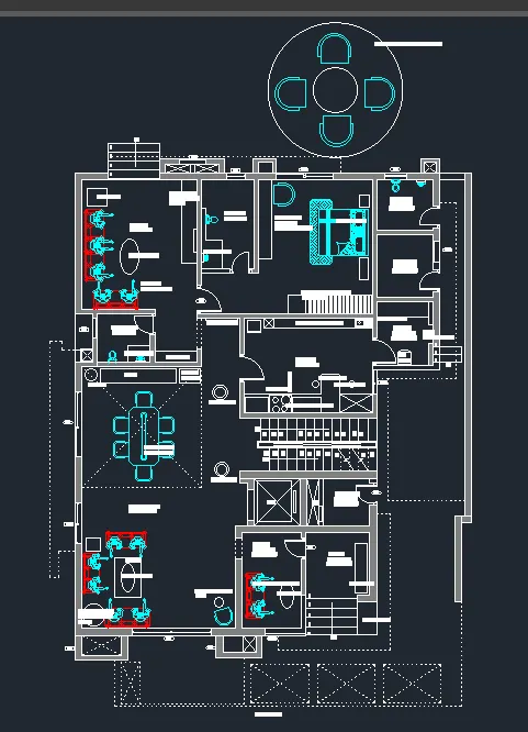
Aim: To draw the floor plan.
Introduction: To draw the floor plan with proper drafting tools to sketch the plan.
Procedure:
- First we need to set the dimension to mm which is given in the drawing.
- Then understand the drawing from which point to start the drawing.
- Take the outer line dimensions and draw the lines by using line command.
- Draw the wall with given dimensions for exterior and interior walls.
- Then take all the dimensions with the room dimensions as shown in the below drawing.
-
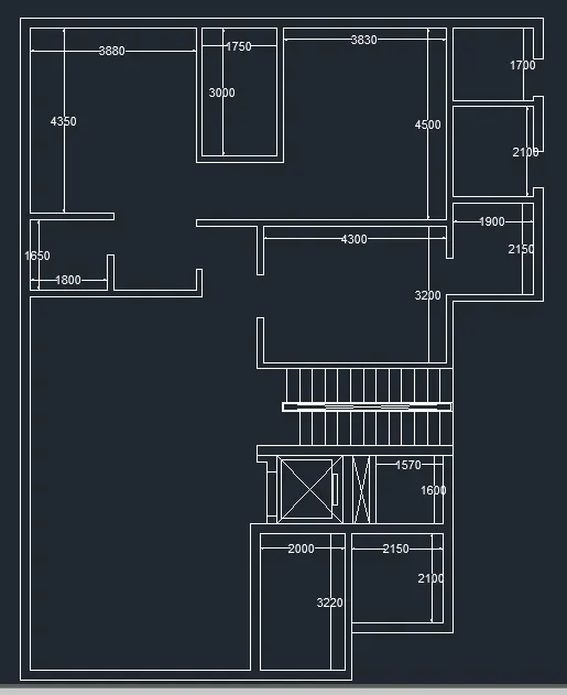
- Staircase has to be provided and assume the dimensions with the given data.
- Lift room to be provided near the staircase after the room dimensions.
- We need to assume some dimensions which are not given in the drawing.
- Then place the furniture area in the bed room areas wherever shown in the drawing.
- Furniture to be drawn and placed separately in the room areas as shown in the below drawing.
-
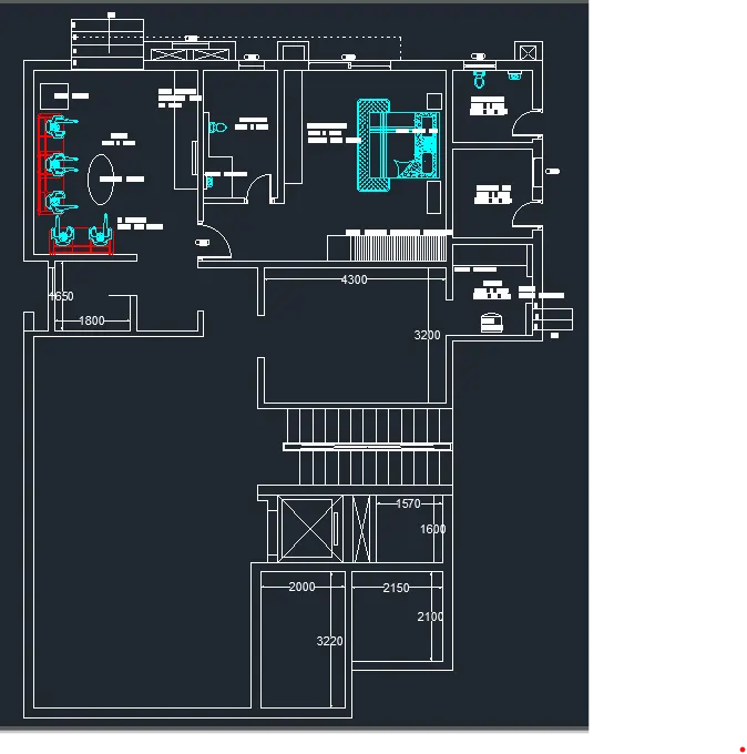
- Then place the furniture in the toilet and kitchen areas as shown in the drawing.
- Now mention the dimensions and room areas by using text command.
- Assume doors and windows area and place the door and windows wherever required.
- Place the platform and tools areas in the kitchen as shown in the below with attached furniture.
-
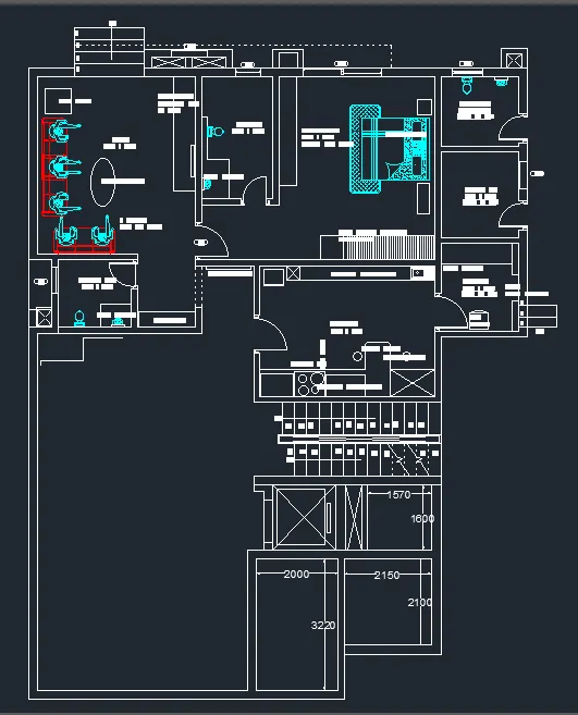
- Now in the same way place the furniture in the remaining room areas.
- There is 8 seater dining in the dining area and place the cupborad and window in the outer wall.
- Now also place the sofa area in the living as in the given drawing.
- Also there is a furniture in the seating plan, assign them in the proper areasas shown in the below drawing.
-
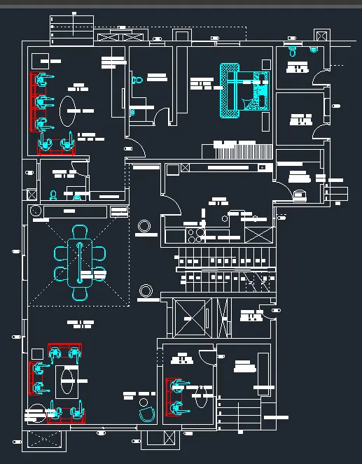
- And there is a final canopy at the top side of the floor plan .
- Draw the canopy by using circle command with assumed radius as in the figure.
- Then place the four chairs around the inner circle
- Place the given furniture which is placed in the figure.
- And finally the drawing is attaced with all the dimensions as attached in the result.
Result:
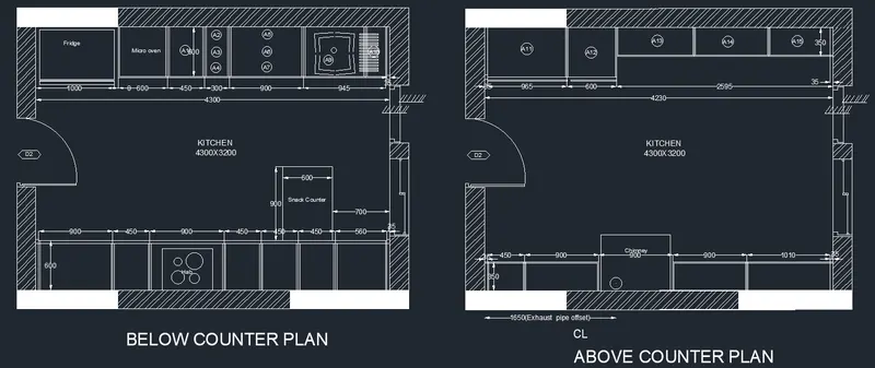
3. Kitchen Layout:
Aim: To design Kitchen layout with proper dimension techniques to dimension the kitchen layout.
Introduction: To design Kitchen layout with proper dimension techniques to dimension the kitchen layout by assuming some dimensions.
Procedure:
- First we need to set the dimension to mm which is given in the drawing.
- Then understand the drawing from which point to start the drawing.
- First take the Below counter plan and by calculating the inner dimesions, assume wall thickness and draw the outer lines.
- Then first you need to draw the outer portion of the drawing by using line command.
- After taking the dimensions, draw the plan by using line and offset command.
- You need to assume some dimensions which are not given in the drawing as shown in the given drawing.
-
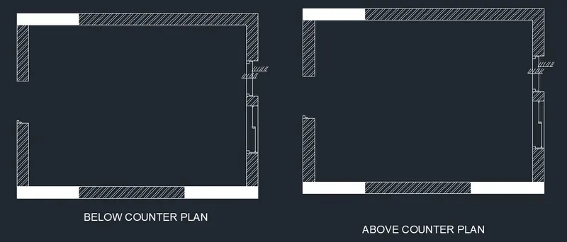
- Now take the given inner dimensions and draw one side at the below counter level plan.
- Then take the assumed door portion and trim the door portion in above and below counter plans.
- Now draw the door with assumed dimensions and insert the door in the trim portion as shown in the drawing.
- Then show the kitchen area and all the area which is given in the drawing.
- Also show the dimension to the inner part which is shown in the drawing as in the attached drawing.
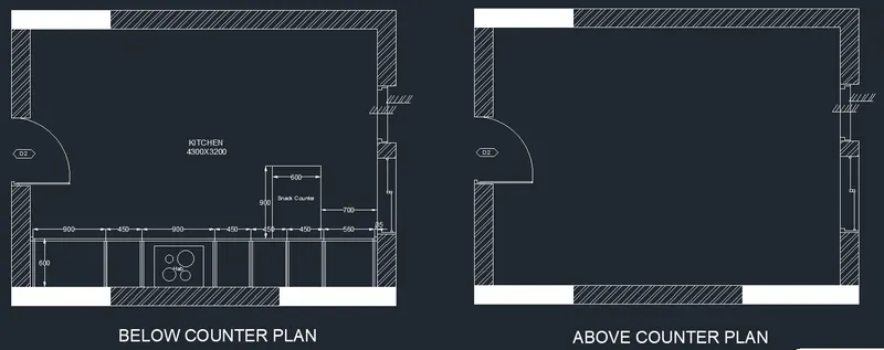
- Now take the given inner dimensions and draw other side at the below counter level plan.
- Now give the hatch to the outer wall as shown in the drawing.
- Then show the kitchen area and all the area which is given in the drawing.
- Also show the dimension to the inner part which is shown in the drawing as in the attached drawing.
-
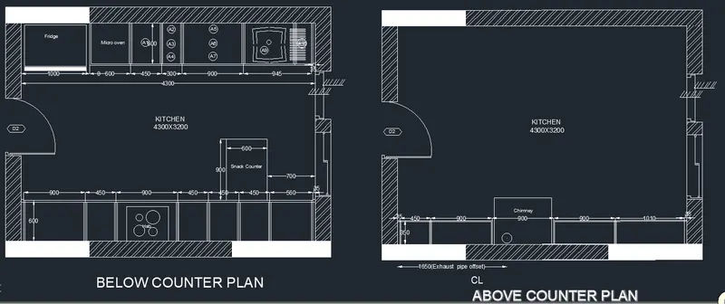
- By using the same procedure, draw the above counter plan.
- Then take the assumed door portion and trim the door portion in above counter plans.
- Now give the hatch to the outer wall as shown in the drawing.
- Finally mention all the dimensions which are given in the attachment and final drawing is attached in the result.
Result:
4.
Aim: To design column details.
Introduction: To design the column schedule as shown in the figure by inserting dimensions and text in the figure.
Procedure:
- First we need to set the dimension in which drawing is given.
- Then understand the drawing from which point to start the drawing.
- Then first you need to draw the reinforcement bars which is given in the table.
- So that after creating the table, then it is easy to insert in the table as shown in the below drawing.
-
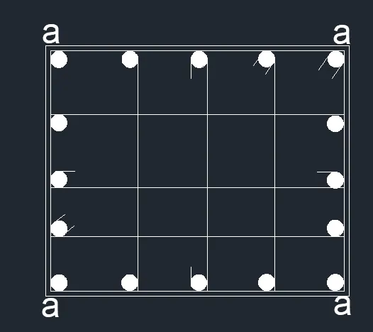
- After creating reinforcement bars, Then start creating the table using line command.
- There are 3 tables separately in the attachment, so we have to draw the outside table.
- By using line command draw the table as shown in the below drawing.
- Now do copy for the remaining 2 table as in the given drawing.
-
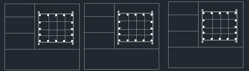
- Then outer line table is ready and reinfocement bar table is inserted in the table.
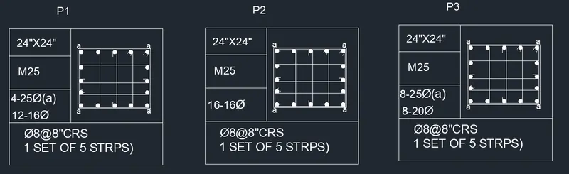
- Now by using text command mention the sizes and details of the column which are given in the attached table.
- In the text, some special characters are there text and we have to upload then by inserting special characters in the ribbons tool bar.
- Then by the same procedure complete doing text to the remaining 2 tables also.
- Finally text should be mentioned for each table as shown in the below drawing.
Result:
5.
Aim: To design raft layout as shown in the figure.
Introduction: To design the raft foundation as shown in the figure by assuming the column sizes.
Procedure:
- First we need to set the dimension in which drawing is given.
- Then understand the drawing from which point to start the drawing.
- Then first you need to draw the outer lines with the given dimensions by using line command.
- After taking the dimensions, draw the plan by using line and offset command.
- You need to assume some dimension which are not given in the drawing as shown in the given drawing.
-
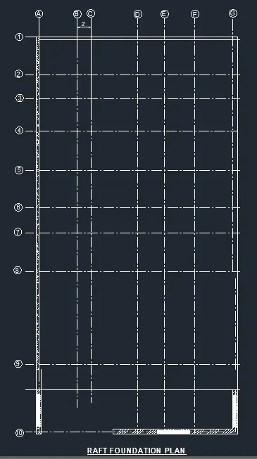
- After creating outer lines, Now we have assign columns by assuming column dimensions.
- Assume the column dimensions, and draw the columns as shown in the drawing by using line command.
- After creating the outer line of the columns, then hatch the column inside the box.
- After placig the columns mention the dimensions clearly from the column to the lines.
- Now place the column in the given places by assuming dimensions as shown in the below drawing.
-
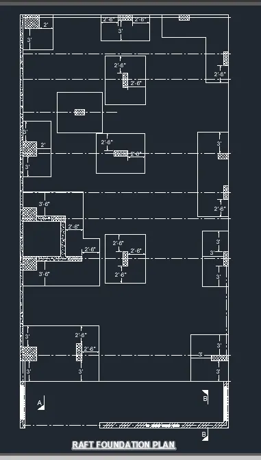
- After placing the columns, mention the clear dimensions from centre to centre columns wherever required.
- Now from the columns, place the names and numbers to the lines as shown in the figure.
- Then it wil get clearly undestand the column sizes and distances.
- You need to assume some dimension which are not given in the drawing as shown in the given drawing.
-
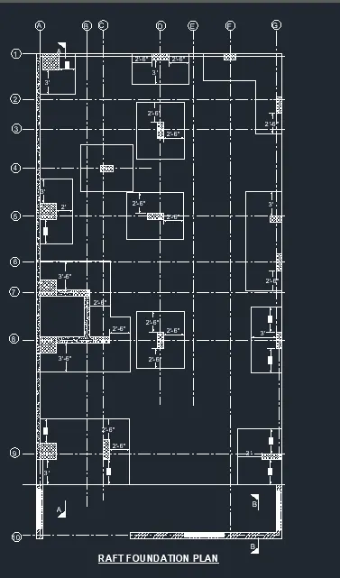
- Then to the points show the dimensions clearly.
- After placig the columns mention the dimensions clearly from the column to the lines.
- Now place the column in the given places by assuming dimensions as shown in the below drawing.
- Hatch the wall portion wherever required as shown in the drawing.
- There 9" wall is mentioned in the drawing by hatching the wall portion.
- Finally show all the dimension and text as shown in the result drawing.
Result:
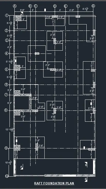
Note: The above drawing result attachements are attached in the pdf format in the below attachements for clear understanding.