Creating a Wardrobe detailed drawing, Floor Plan, Kitchen Layout and Column Detail using AutoCad
1. Draw the elevation and details of a wardrobe as shown in the Figure below. After sketching, you need to provide the dimensions and text with the use of layers. Use proper text styles and dimension methods to document it. Also, assume dimensions, wherever needed.
Note: All dimensions are in mm.
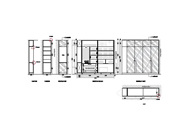
Aim:
To draw the elevation and details of s wardrobe as shown in figure using the AutoCAD 2023 software
Introducton:
Draw the elevation and details of a wardrobe as shown in the Figure. After sketching, you need to provide the dimensions and text with the use of layers. Use proper text styles and dimension methods to document it. Also, assume dimensions, wherever needed.
Note: All dimensions are in mm.
Procedure:
Step-1: Open the software and fix the units
- Open the AutoCAD software
- The unit of this drawing is given as shown in below
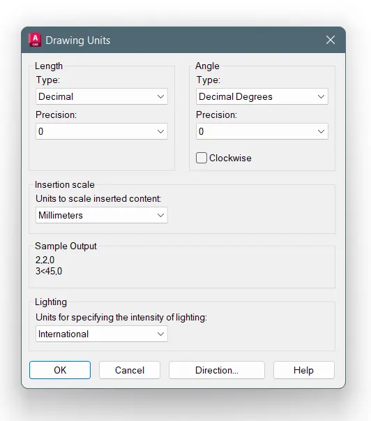
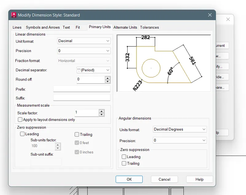
- The line length is Decimal and the precision is 0
- And then, giving the limits is 0,0 to 50000,50000
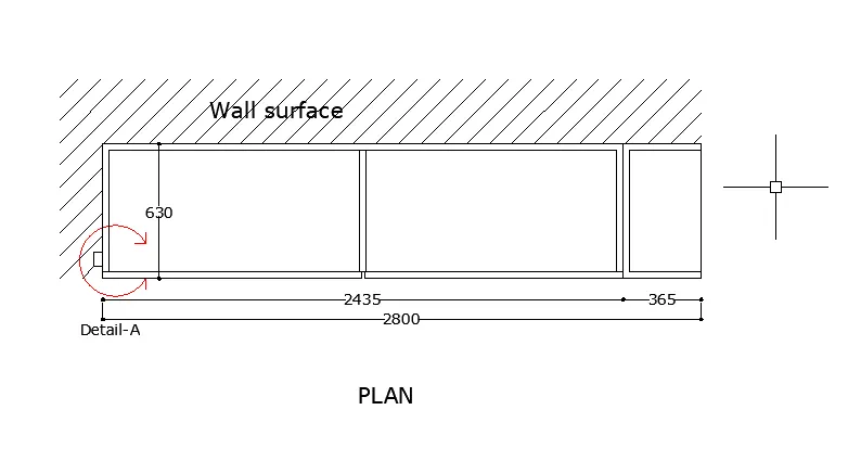
Step-2: To draw the plan
- Using the Line command to draw the wall suface as in given sketch
- Here used commands are MText, Hatch, Arc, Dimstyle and the Dim from Annotate panel
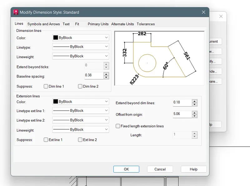
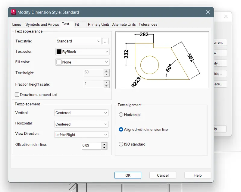
Step-3: To edit the Dimestyle
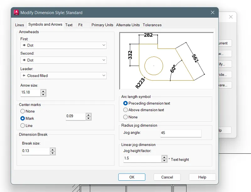
- The symbols and arrows, Lines, Text, Primary units are given as below figures
- This values are currectly set in the drawings
- As shown in the coming drawing
Step-4: To edit the text
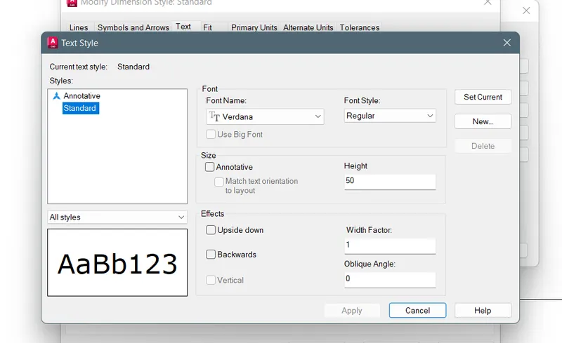
- The Font name is Verdana
- Text height is 50
- And click Set Current and then click Apply, then click Cancel
- The steps are given as above values
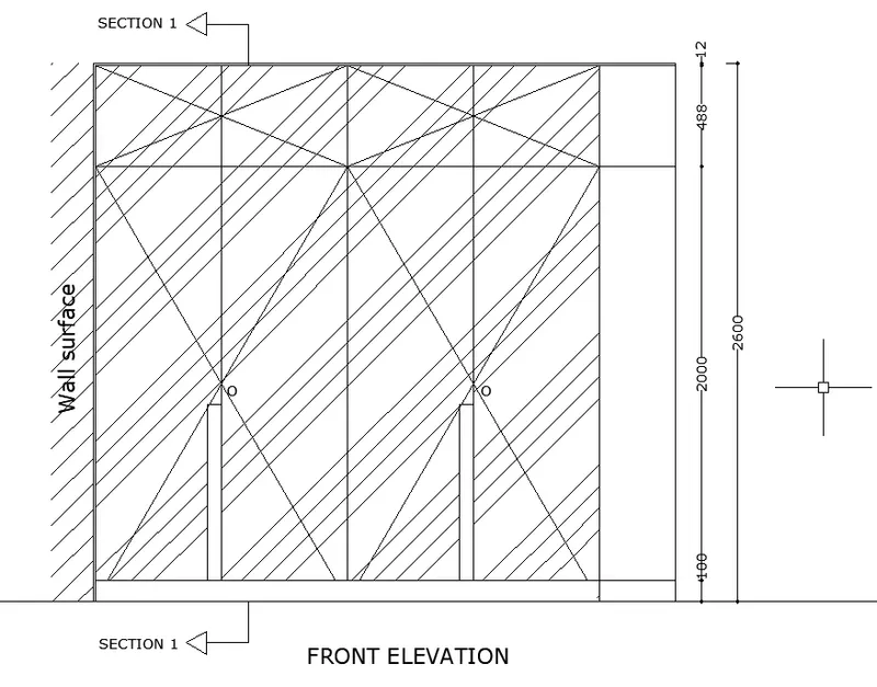
Step-5: To draw front elevation
- Here, this drawing drawn as given values in question
- In this drawing is contains Hatch command is used
- ANS134 type of hatch is used and the scale is 1
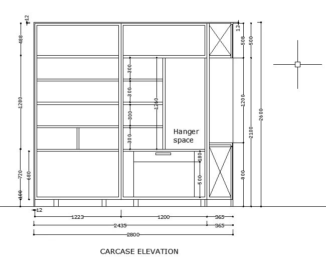
Step-6: Carcase elevation
- This drawing is drawn using line command
- And using MText (MT) command
- The length is measured as drawn in given question
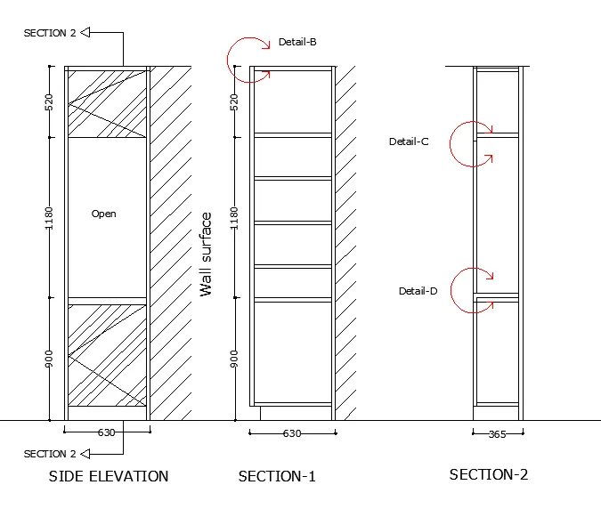
Step-7: To draw side elevation, section-1 and section-2
- Here, the section drawings and the elevation drawings is drawn as already shown commands
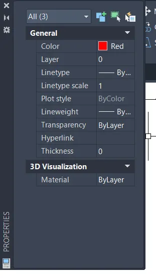
- The Arc layer is gave as below figure
Step-8: Finish the model
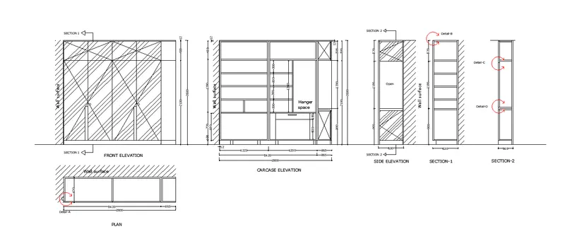
- The drawing is finally drawn as given in the question
- And then, finally screenshot this drawing using the Snipping Tool
- The shortcut of snipping tool is Windows key+Shift+S
Result:
The given Cabinet drawing is drawn using the AutoCAD 2023 software
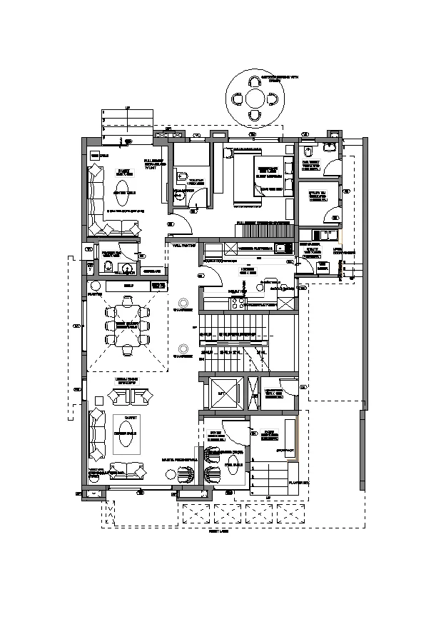
Q2. Draw the floor plan as shown in the Figure. Use the proper drafting tools to sketch the plan. Do not hatch or draw the furniture. You need to draw the floor plan with the following:
Note: You can also import the Floor_Plan.pdf into your current drawing and start working on the project. You need to scale the imported pdf file using reference option. All dimensions are in mm.
- Walls (Exterior and Interior)
Wall Thickness: Exterior Wall- 230mm, Interior Wall: 150 mm (Wherever Required)
- Doors and Windows: Assume the size of the doors and window.
2.1 Stairs: Tread-300mm, Riser-150mm
- Insert Text wherever required
- Insert the dimensions using proper dimension techniques
Aim:
To draw the floor plan of given model drawing using the AutoCAD 2023 software
Introduction:
Draw the floor plan as shown in the Figure. Use the proper drafting tools to sketch the plan. Do not hatch or draw the furniture. You need to draw the floor plan with the following:
Note: You can also import the Floor_Plan.pdf into your current drawing and start working on the project. You need to scale the imported pdf file using reference option. All dimensions are in mm.
- Walls (Exterior and Interior)
Wall Thickness: Exterior Wall- 230mm, Interior Wall: 150 mm (Wherever Required)
- Doors and Windows: Assume the size of the doors and window.
2.1 Stairs: Tread-300mm, Riser-150mm
- Insert Text wherever required
- Insert the dimensions using proper dimension techniques
Procedure:
Step-1: To set the units
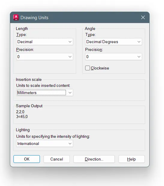
- The unit was setting up as shown in figure
- The length type is Decimal and precision is 0
- And then, the Insertion scale is Millimeter
Step-2: To set up the text style
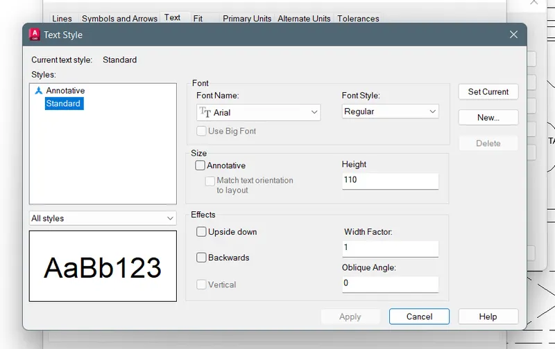
- The font name is Arial
- Font style is standard and the Height is 110
- Then, click Apply and click cancel to back that tab
Step-3: To draw plan drawing
- Draw the plan drawing using the Line command
- Give the Offset command to the outer wall size of 230mm and inner side wall thickness of 150
- Using the Chamfer command for connecting the two lines in corner
- Using line and Arc coomads to create the doors and i am assuming the size of the door
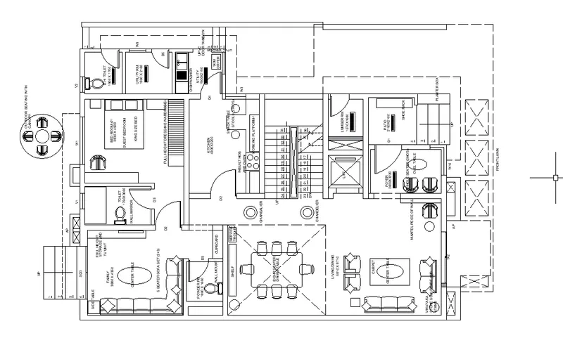
- The Sofa, Table and the chairs created by assumption sizes
- Here, Canopy was created by the assuming size
- The interior fixtures are created by own idea
- The Text is given by using the MText command and click the screen where i want text
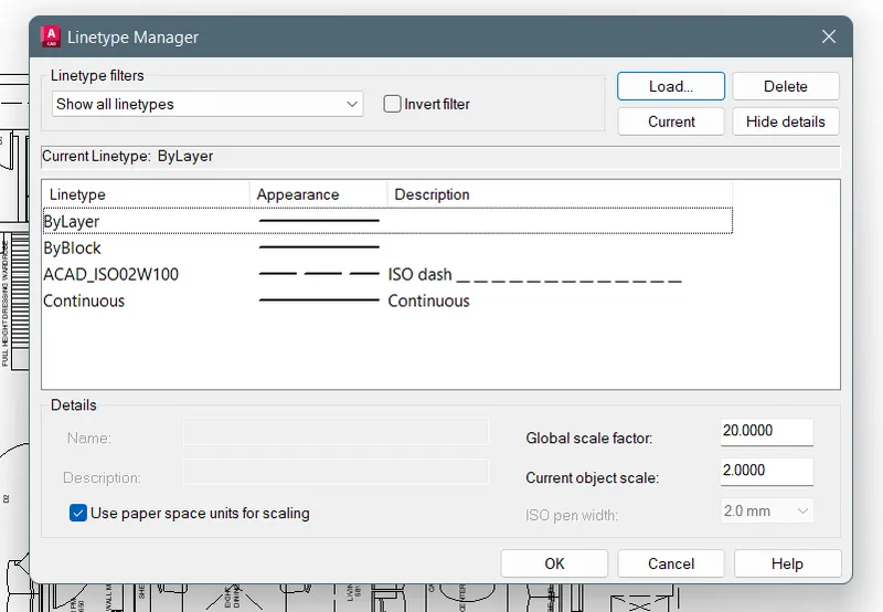
- The outer lintel and roof extensions are drawn using the line (ISO dash)
- And give the scale is given as shown in figure
- First click Bylayer for edit the line type
- And Click load and then, click that line type finally click OK
- Use this Bylayer for the roofs and lintels
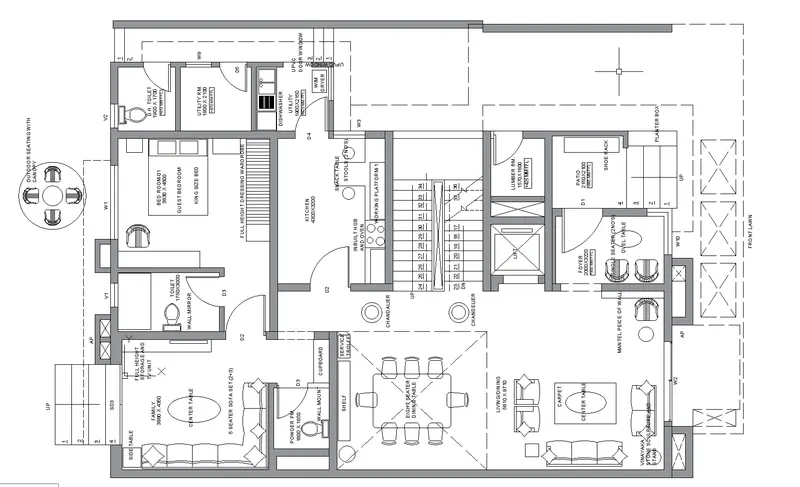
- Here, using the Hatch command for identify the walls
- Type the Hatch (H) command in command box
- And select Solid and click Pick point and then, select the wall areas to give the hatch
- Then, change the hatch color to gray
- The drawing is finally drawn as given in the question
- And then, finally screenshot this drawing using the Snipping Tool
- The shortcut of snipping tool is Windows key+Shift+S
Result:
The given Floor plan was drawn using the AutoCAD 2023 software with refer the given dimensions and assume the sizes of other items
Q3. Create the Kitchen Layout as shown in the Figure below. Also, use proper dimension techniques to dimension the kitchen layout. Also, insert text wherever required. All dimensions are in mm.
Aim:
To create the Kitchen Layout using the AutoCAD software and refer the dimensions as given in the question
Introduction:
Create the Kitchen Layout as shown in the Figure. Also, use proper dimension techniques to dimension the kitchen layout. Also, insert text wherever required. All dimensions are in mm.
Procedure:
Step-1: To set the Units
- Open the AutoCAD software
- The unit of this drawing is given as shown in below
- The length type is Decimal and precision is 0
- Insertion scale is Millimeter
- Finally click OK
Step-2: To draw the Kitchen plan
- First of all uisng the Line command for draw the outer wall
- The Chamfer command to join the corner lines with eachother
- And create the door using the line and arc commands
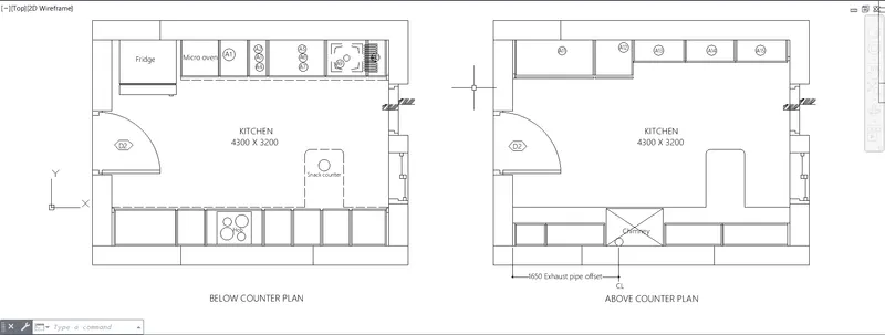
- And give the scale is given as shown in figure
- First click Bylayer for edit the line type
- And Click load and then, click that line type finally click OK
- For the snack counter line in below counter plan
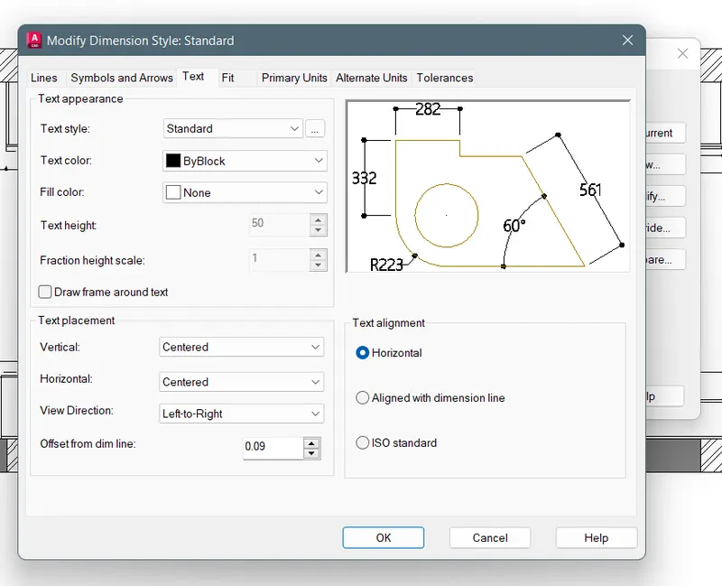
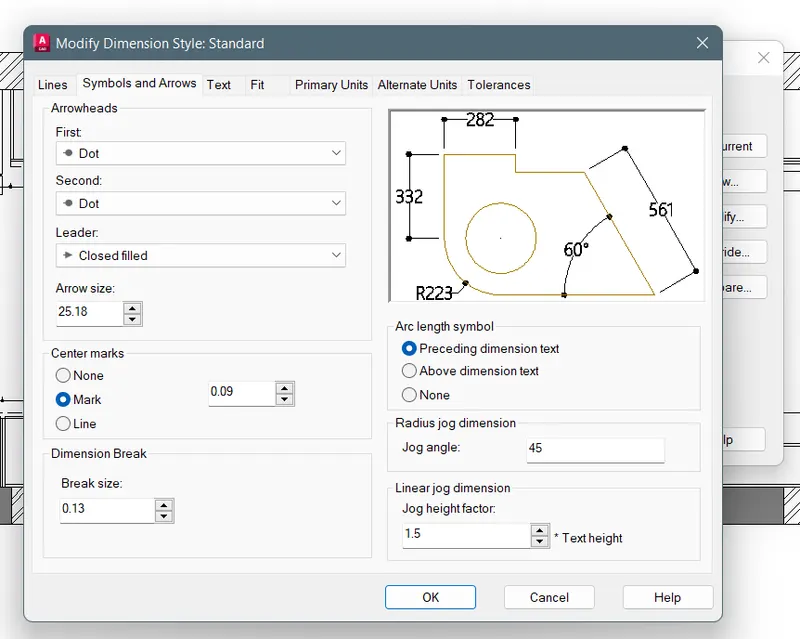
Step-3: To set up the Dimension style
- The Dimension style was edit as given below drawing
- First type in command box as Dimstyle
- Give the values are as shown in below figure
- Click Modify button
- Finally click OK, Setcurrent and then, finally click close
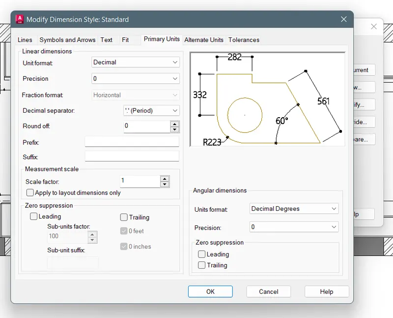
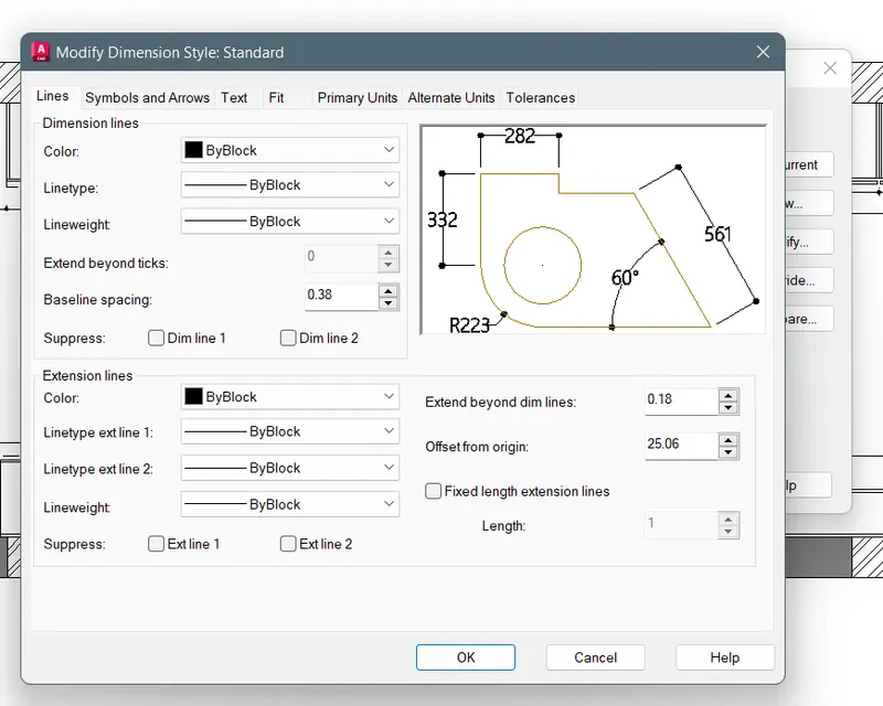
- Here, the Line, Symbols and Arrows, Text and Primary units are fix as in the all details
Step-4: To give dimension
- The dimensions are given by uisng the Dim command
- Then, click the points where i want to give the dimensions as given in the question
- Texting by using MText command in where i want to give the text
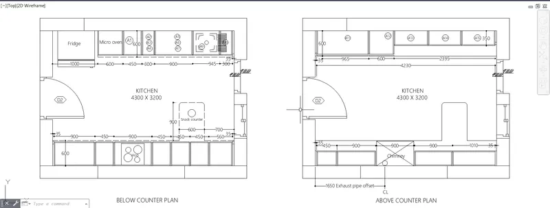
- The Hatches are using the Hatch command with the solid and wall hatch is used for giving the identify the walls
- Then, finish the drawing
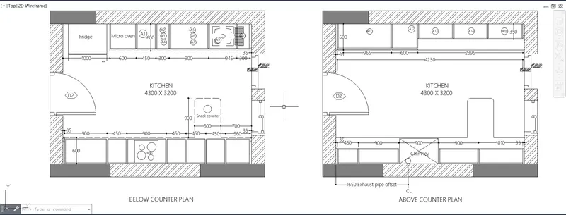
Step-5: Finish the model
- The drawing is finishing by uisng the dimensions are given in the question
- The drawing is finally drawn as given in the question
- And then, finally screenshot this drawing using the Snipping Tool
- The shortcut of snipping tool is Windows key+Shift+S
Result:
The Kitchen layout plan was drawn using the AutoCAD software with refer the dimensions given in the question drawing
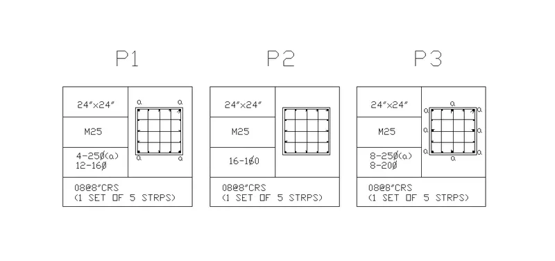
Q4. Sketch the column details as shown in Figure. Insert dimensions and text in the figure. Refer to the bar sizes from the schedule.
8mm ---- 0.31 Inches
25mm--- 1 inches
16mm—0.62 inches
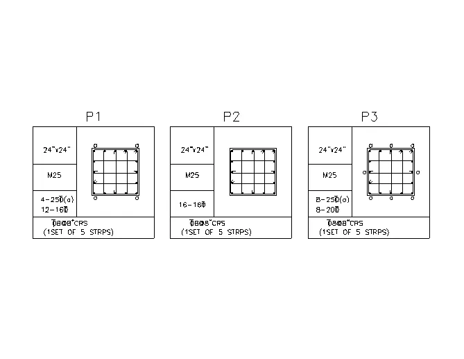
Aim:
To sketch the column details drawing as shown in figure by using the AutoCAD software with the given sizes
Introduction:
Sketch the column details as shown in Figure. Insert dimensions and text in the figure. Refer to the bar sizes from the schedule.
8mm ---- 0.31 Inches
25mm--- 1 inches
16mm—0.62 inches
Procedure:
Step-1: To set units
- The length type is Engineering and the precision is 0'-0.00"
- The insertion scale is Inches
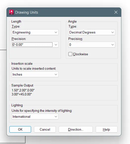
Step-2: To sketch the column details
- Here, using the Line command for draw the column and the sketch the table for giving the details as in the question
- Draw the circle for rod using the circle command and give the hatch command for identify the rod as given in the question
- And give the text by default font style
- Then, give the text height is 8"
- Finally text the content and scale it
Step-3: Finish the model
- The drawing is finishing by uisng the dimensions are given in the question
- The drawing is finally drawn as given in the question
- And then, finally screenshot this drawing using the Snipping Tool
- The shortcut of snipping tool is Windows key+Shift+S
Result:
The column deatils sketch was drawn by using the AutoCAD software with the using of given dimensions for draw the column and assume the table sizes
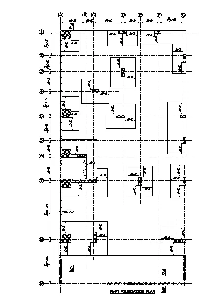
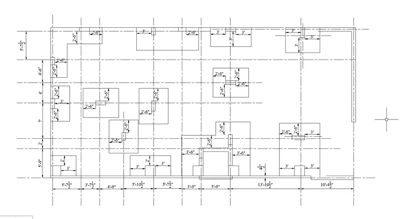
Q 5. Draw the Raft Layout as shown in the Figure. Assume the column size as per your knowledge. You can take the sizes as: 24”x24”, 9” x 24”, 9” x 18”, and 9’ x 24”. You can import the raft_foundation.pdf to ensure the missing dimensions.
Aim:
To draw the Raft Layout as shown in the Figure using the AutoCAD software
Introduction:
Draw the Raft Layout as shown in the Figure. Assume the column size as per your knowledge. You can take the sizes as: 24”x24”, 9” x 24”, 9” x 18”, and 9’ x 24”. You can import the raft_foundation.pdf to ensure the missing dimensions.
Procedure:
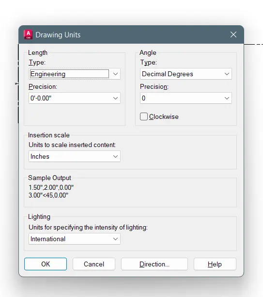
Step-1: To set the units
- The line legth type is Engineering and the precision is 0'-0.00"
- The insertion scale is Inches
Step-2: To change the line type
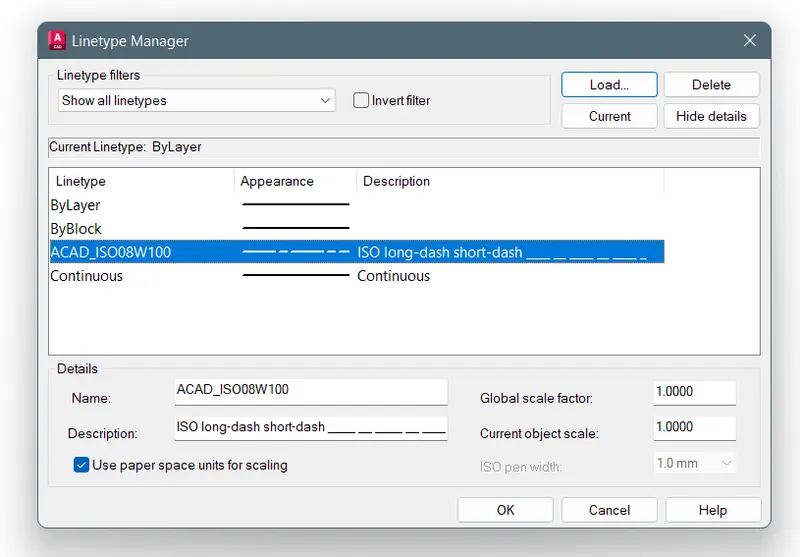
- The line type is change using the Bylayer tab
- Click the Load button and ISO long-dash short-dash type of line is loaded for draw the layout grid line
- Then, click OK button
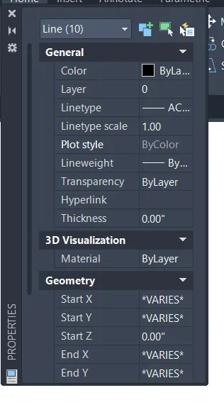
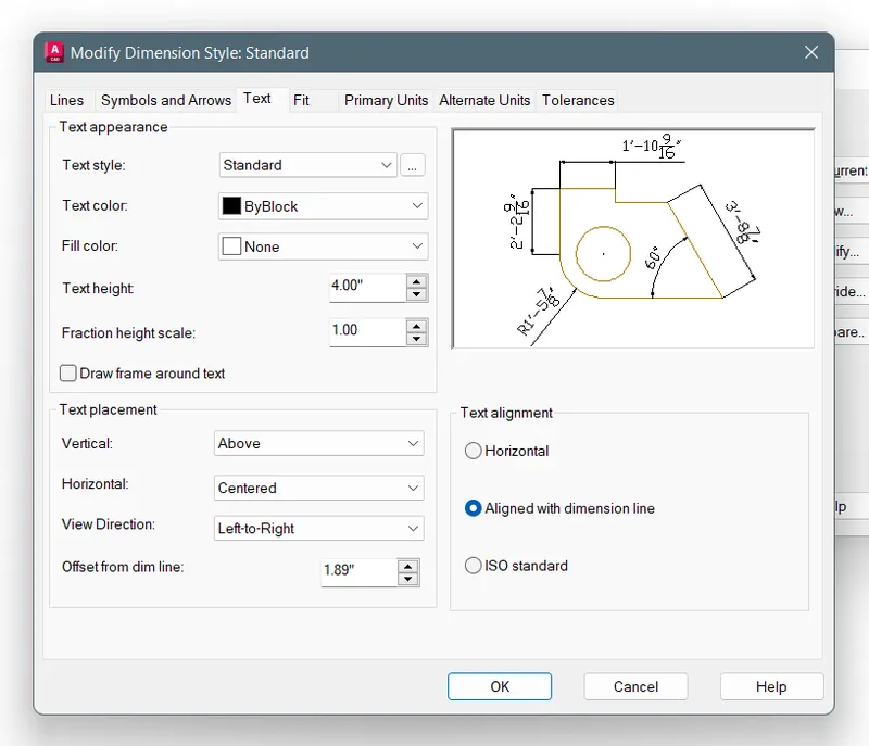
Step-3: To set up the Dimstyle
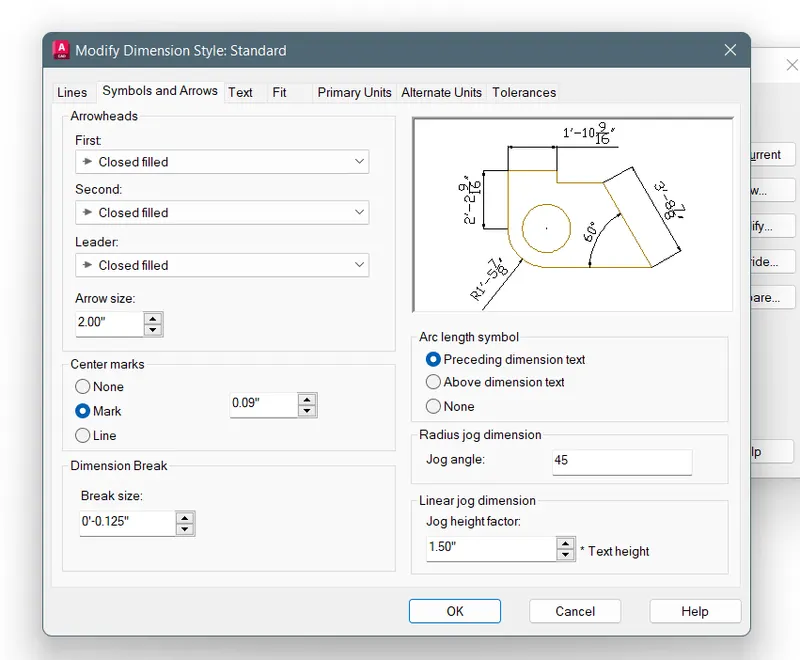
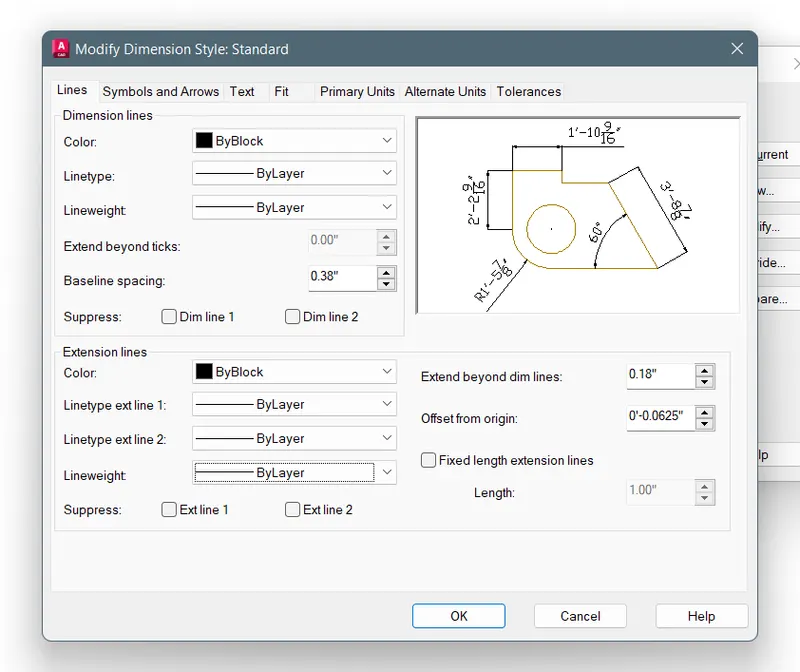
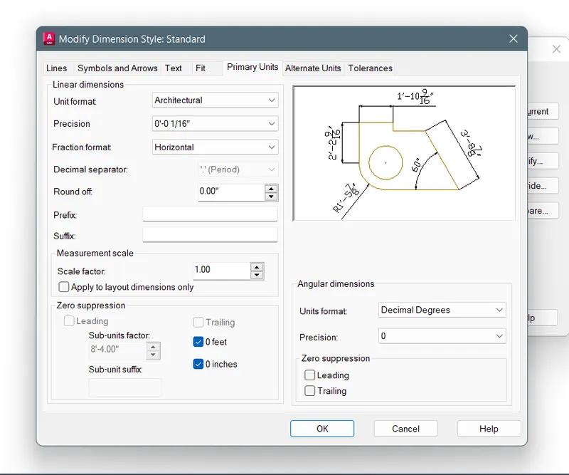
- Type the Dimstyle command in command search box
- Then, edit the all kind of details i want as we saw the above drawings
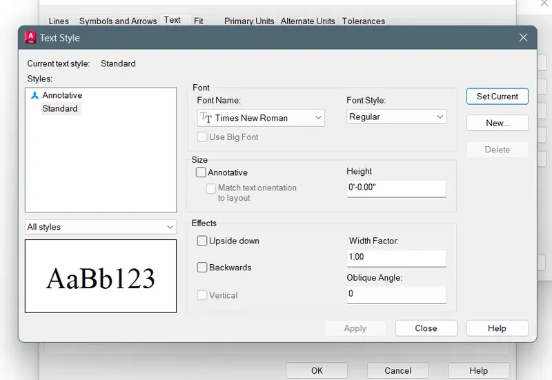
Step-4: To set up the text
- Select the font name is Times new roman
- And then, click the Apply
- Finally Click Close
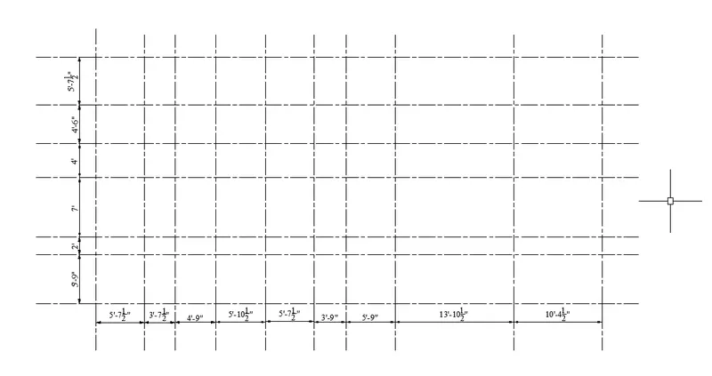
Step-5: To draw the Raft layout
- By using the Line command as given in the question drawing to refer the dimensions
- Draw the Line to for draw the column and footing
- Draw the column as given in the question is shown in below figure
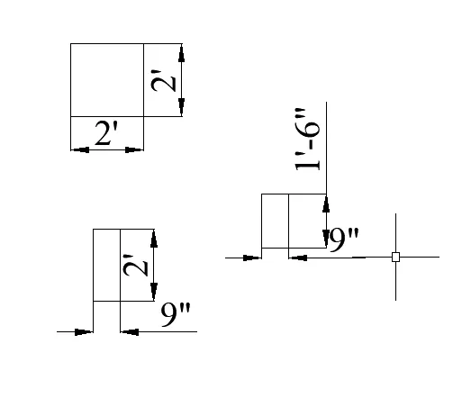
- Fix the column in grid lines depends in the size of footing and the column
- The footing is drawn using the Line command and the dimension is give in where i want
- The walls are drawn by using the line command
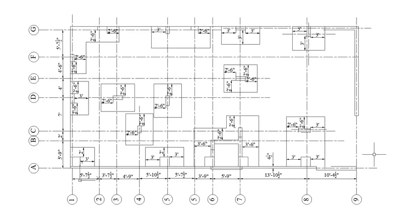
- The gris line name is given for identify the marking of column
- Here, using the Circle command and fix the text inside of the circle
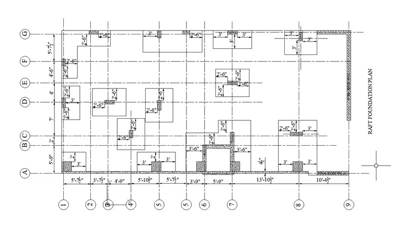
- The Hatch for the column and the walls
- Here, the we are using the threen types of hatches for identify the columns and the walls
- Finally text the drawing title
- This drawing is drawn by the given sizes and the dimensions
Step-6: Finish the model
- The drawing is finishing by uisng the dimensions are given in the question
- The drawing is finally drawn as given in the question
- And then, finally screenshot this drawing using the Snipping Tool
- The shortcut of snipping tool is Windows key+Shift+S
Result:
The Raft foundation layout is drawn using the AutoCAD 2023 software with refer the all dimensions for the draw this sketch