Creating a Wardrobe detailed drawing, Floor Plan, Kitchen Layout and Column Detail using AutoCad
DRAWING 1
AIM
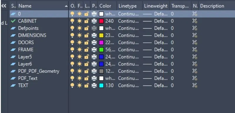
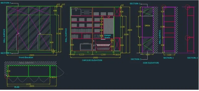
To draw the elevation and details of the wardrobe as shown in the figure. After sketching, you need to provide the dimension and text with the use of layers.
COMMANDS USED
1.Line
2.Rectangle
3.Offset
4.Trim
5.Extend
6.Hatch
PROCEDURE
1.Set limits and units
2.Draw a rectangle (2800,2600)
3.Offset from top of the dimension 12mm and 488mm
4.Offset side at a distance of 608.75mm and 365mm
5.Draw a line to increase the transparency to create a wall surface
6.Type qleader to mention the annotation
7.Draw a rectangle (630,2800) and type qleader to mention the annotation
8.Draw a rectangle (2800,2600) and type qleader to mention the annotation
9.In the command type rectangle and the dimension of 520*630, 1180*630, 900*630 and repeat two times
10.Draw next line using line command
RESULT
The elevation and details are drawn as shown in figure.
DRAWING 2:
AIM
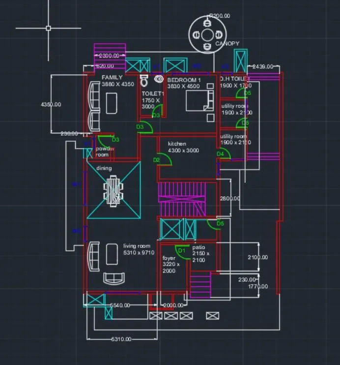
To draw the given floor plan
COMMANDS USED
1.Line
2.Rectangle
3.Offset
4.Trim
5.Extend
6.Hatch
PROCEDURE
1.Set the limit and unit
2.Type XL to draw infinite lines
3.use offset wherever needed
4.Use arch for doors
5.In the command line, "adc" typed to get the components of the plan
6.In the command line "line type" is typed to get dotted lines
7.In the command line "text" is typed to get the dimension and annotation of the plan
8.To draw canopy
9.Draw a circle of radius 1398mm
10.Draw another circle of radius 452mm
11.Offset 200mm inside for the position of chair
12.Draw lines for a bigger circle
13.Draw a rectangle of 400mm,200mm and draw an arch for the chair
14.Draw another rectangle of 55mm*100mm for the handle of the chair
15.Copy it on another side so that both handles are formed.
RESULT
Given floor plan is drawn using AutoCAD.
DIAGRAM 3:
AIM
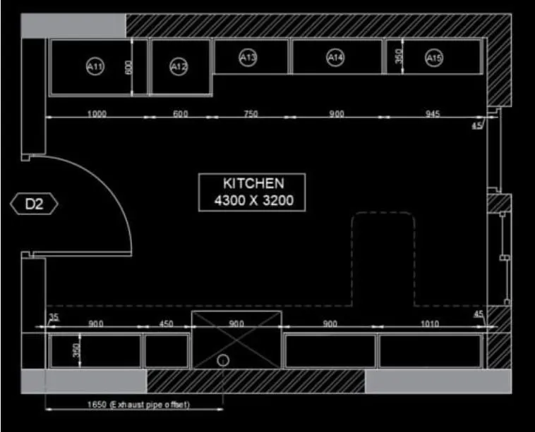
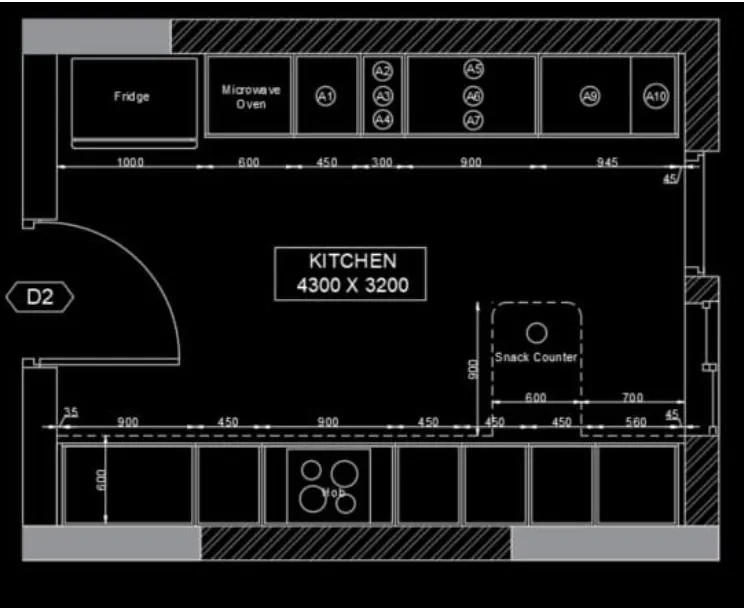
To create the kitchen layout and to also, use proper dimension technique to dimension the kitchen layout. Also, insert text wherever needed. All the dimensions are in mm.
COMMANDS USED
1.Line
2.Rectangle
3.Offset
4.Trim
5.Extend
6.Hatch
PROCEDURE
1.Draw a rectangle of (4734,3688) mm
2.The offset of 230mm should be done for wall thickness
3.Use arch command for doors
4.Hatching should be done to show brickwork
5.Using rectangle command draw fridge
6.Offset should be done to draw micro oven
7.Trim to trim extra lines
8.Offset horizontal distance of 350, 450, 900, 450, 450, and 560
9.Trim extra lines
10.Mention the dimension using the dimension command.
RESULT
The kitchen layout is created as shown in figure.
DRAWING 4:
AIM
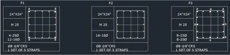
To sketch the column details as shown in the figure. Insert dimension and text in the figure. Refer to the bar size from the schedule
BAR SIZE
1.8mm - 0.31inches
2.25mm - 1inch
3.16mm - 0.62 inches
COMMANDS USED
1.Line
2.Rectangle
3.Offset
4.Trim
5.Extend
6.Hatch
PROCEDURE
1.Using rectangle command and line command the tables are drawn
2.Using text command the text is given
3.Draw a line for reinforcement
4.Draw a circle to show the reinforcement
5.Draw a draft layout as shown. Assume the column size as per requirement
6.The remaining P2 and P3 columns are the same as the P1 column
RESULT
The column details are sketched using AutoCAD.
DIAGRAM 5:
AIM
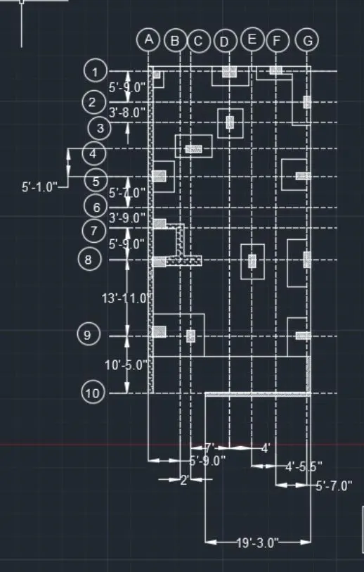
To draw the raft layout
COMMANDS USED
1.Line
2.Rectangle
3.Offset
4.Trim
5.Extend
6.Hatch
PROCEDURE
1.Draw a rectangle of 29'9", 60'
2.Change the line type to the dotted line
3.With the help of dotted lines and offset command the grids are drawn
4.Offset the distance of 4"
5.Draw a rectangle of 2',2'
6.In the ribbon bar select Hatch > ANS137
7.In the ribbon bar > Annotate > m text to text the given annotation
8.In the ribbon tab > dimension > to given the dimension
RESULT
The raft layout is created using AutoCAD.