Creating a Wardrobe detailed drawing, Floor Plan, Kitchen Layout and Column Detail using AutoCad
1) Aim: To draw the elevation and details of a wardrobe as shown in the Figure.
Procedure:
- Open Auto cad and open new drawing.
- Type ‘LIMITS’ in command bar and set the sheet limit as per drawing.
- Type ‘UNITS’ in command bar and set the unit type as Decimal and unit in millimeters set precision as required for drawing.
- Keep ortho on so that the lines move only in Right angles.
- First draw the plan of the wardrobe.
- Use the given dimension of wooden thickness.
- Using rectangle command shows the wall thickness.
- The wall placement is given in the drawing.
- Use hatch and select the wall hatch and select the rectangle area.
- The wall hatch arrives and then deletes the rectangle.
- After plan next draw the Front elevation using the plan.
- Change the line weight of some line where there is a need of light line.
- After drawing the elevation next draw the Carcase elevation using plan and front view.
- Then do the dimensioning of the completed drawings.
- Go to dimension style and select the dot instead of arrow.
- Before starting the dimension work go to prefix and select decimal as 0.
- Because the arrow will take the more place and makes hard to visible.
- Using the dot we can easily do the dimensioning.
- After all the drawing completed like sections and all do the dimensioning and complete it.
- Now use Mtext and do the naming using the text where ever needed.
- Set the size of text so that it is very clear and visible.
Result:
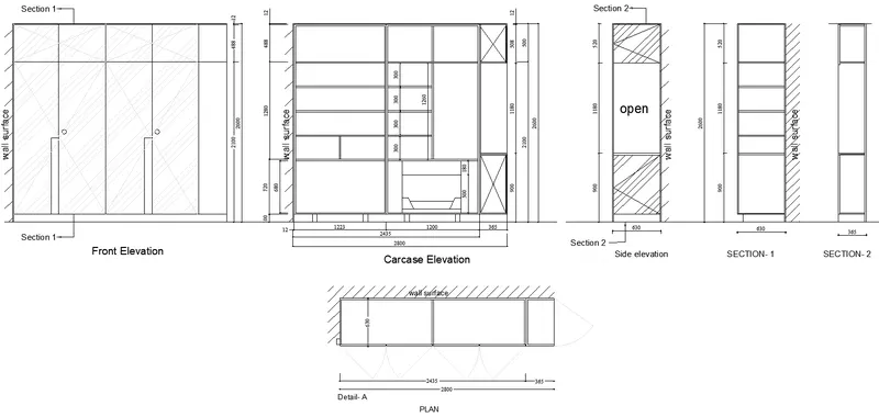
Note: Clear Image is attached below.
2) Aim: To draw the floor plan as shown. Use the proper drafting tools to sketch the plan.
Assumption: Door sizes:1200mm, 1000mm & 900mm.
Window size: 1800mm, 1200mm & 1000mm.
Ventilator: 600mm.
Procedure:
- Open Auto cad and open new drawing.
- Type ‘LIMITS’ in command bar and set the sheet limit as per drawing.
- Type ‘UNITS’ in command bar and set the unit type as Decimal and unit in millimeters set precision as required for drawing.
- Keep ortho on so that the lines move only in Right angles.
- Use construction line and draw the outer line of wall.
- Use offset command and show all the thickness of wall and room thickness.
- Trim off the extra line using the trim command or fillet command.
- In fillet command keep radius 0 the we will get sharp edges.
- After clearing all the extra lines now start with fixing the door.
- The doors are fixed with respect to the sizes and places foe ease movement.
- Use the line command and draw the centre line of the door and using offset command do the full width.
- After that trim off the middle lines.
- Again use line command and draw the door frame and the door.
- Then using arc show the direction of swing of the door.
- Do the same step for the entire door with different sizes.
- Now start with the window, do this same as done in door.
- Just show the 2 lines in between to show the placement.
- Same with the ventilators also.
- Do the steps in the shown placement with the given measurement in question.
- Now the major parts are done next do with the Chajja.
- Create a layer with dotted lines and make a Chajja where ever required.
- Now start to do the naming of the door and windows.
- As we assumed the values name with D1, D2 & D3.
- Same for window W1, W2 & W3. V1 for ventilators.
- Do the naming of the room as given with their dimensions.
- Show the Floor Finish Level where ever required.
- Make sure the size of text is clearly visible and won't merge each other.
Result:
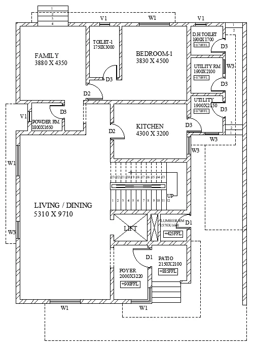
Note: Non of the shaft has be drawned in above drawing because due to lack of dimensions.
3) Aim: To create the Kitchen Layout as shown in the Figure.
Procedure:
- Open Auto cad and open new drawing.
- Type ‘LIMITS’ in command bar and set the sheet limit as per drawing.
- Type ‘UNITS’ in command bar and set the unit type as Decimal and unit in millimeters set precision as required for drawing.
- Keep ortho on so that the lines move only in Right angles.
- Use line command and draw the outer wall and inner wall of the room.
- Next do the door using line and trim command.
- Use line command to show the frame and door length and thickness.
- Start with the below counter plan which includes stove sink and fridge etc.
- Trim off the lines carefully here trimming plays a major role.
- See in given drawing where the cutting is and where to be trimmed.
- After completing the drawing start with dimensioning.
- Select dotted in the dimension style and start the dimension.
- Before starting the dimension work go to prefix and select decimal as 0.
- Select the linear dimension and then select continue dimension.
- Now we have to only click of which we need dimension.
- It automatically starts from where we ended last.
- Then use Mtext and do all the naming where ever required.
- Make sure that the dimension and text size are clearly visible.
Result:
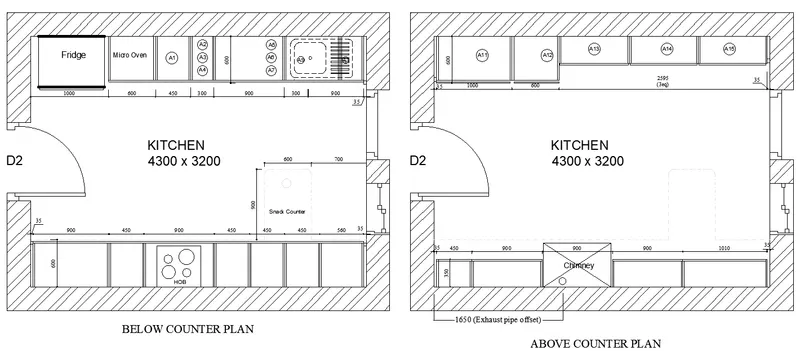
Note: Clear Image is attached below.
4) Aim: To sketch the column details as shown in Figure.
Procedure:
- Open Auto cad and open new drawing.
- Type ‘LIMITS’ in command bar and set the sheet limit as per drawing.
- Type ‘UNITS’ in command bar and set the unit type as Decimal and unit in Inches set precision as required for drawing.
- Keep ortho on so that the lines move only in Right angles.
- Using line command makes a table where the drawing has to be done.
- Now trim off the all extra lines using trim or fillet command.
- Start to do the naming with the mentioned text and size.
- Go to dimension style and select the given text style.
- Does the entire column size naming concrete grade naming and stirrups detail.
- After completing the above naming part start to draw the column cross section.
- Assume the cover and show the stirrups.
- Show the vertical rod dia using the donut command.
- Select the centre point anywhere in screen and give the internal dia as 0 and then the external dia as any required dia.
- Make these of several dia for different size then apply where ever needed.
- Show the extra stirrups with line command.
- Do the curve of the stirrups using the fillet command.
- By providing the radius of any required.
- Do the stirrups end bent of 135 degree using the arc command and adjust as required.
- Do the same foe all column cross section.
Result:
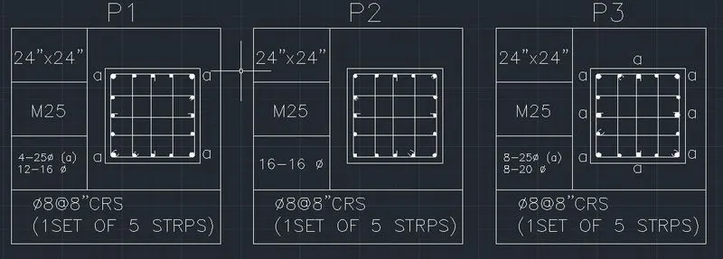
5) Aim: To draw the Raft Layout as shown in the Figure.
Procedure:
- Open Auto cad and open new drawing.
- Type ‘LIMITS’ in command bar and set the sheet limit as per drawing.
- Type ‘UNITS’ in command bar and set the unit type as Architectural and unit in Inches set precision as required for drawing.
- Keep ortho on so that the lines move only in Right angles.
- Select the construction line command and draw a vertical line.
- Next using offset command draw all the centerline using the dimensions given.
- Use the fractional dimension while doing offset.
- Now start to do with the horizontal lines and again use offset command and complete the centerline.
- In the other case the centerline drawing is done with the help of column.
- But here we don’t have the column centre to centre distance so use the centerline method.
- After all the centre line drawn now using the cross junction place the column.
- The size of the column is given in the question so use that.
- See in which cross mark does the column lies and with respect to shown draw the drawing.
- After that the RCC retaining wall is shown in the drawing does that.
- Next the Brick masonry wall is provided show that.
- After doing all the things now do the footing.
- The footing size from the column is given so draw with respect to that.
- Use the offset command for the footing.
- Does the footing from the column and using fillet command with radius 0 join the lines.
- Then do the dimensioning work of footing.
- Next show the centre line distances.
- First show one dimension and next use continues and select the lines and do all the dimensioning.
- Next select all and move as per requirement.
- Make several layers for Centerline, dimension, column and footing so it is easy for further editing’s if required.
- The centerline layer line type should be dotted.
- After all the drawing work now the major is naming the centerline.
- Draw a circle so that the text in that should be clearly visible.
- Type Mtext and select in the circle.
- In the X-Axis name the lines in Alphabetic order and in Y-Axis name the lines in numerical.
- Now select all and copy for the opposite sides in both direction.
- Use move command for minor displacements.
- Set the size of the text so that they are clearly visible. The dimensions are also being made sure that they are clear and visible.
Result:
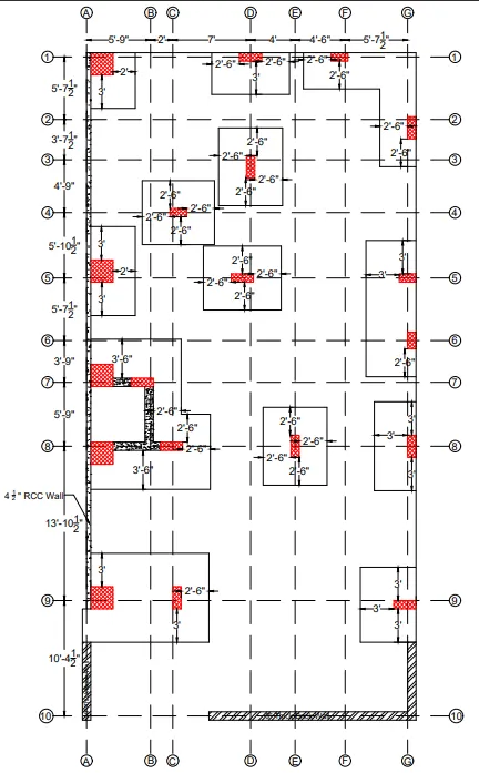
The result is attached below.