Creating a Wardrobe detailed drawing, Floor Plan, Kitchen Layout and Column Detail using AutoCad
1Q]
AIM: -
Draw the Elevation and details of the wardrobe
Insert dimensions and text
Use Layers
PROCEDURE: -
Choose command: UN for drawing units
Set length type to DECIMAL.
Set the lower limits and Higher limits using LIMITS command
Select command XLINE
Draw Vertical line and Horizontal line.
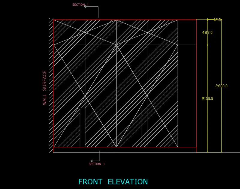
Use drawing tools to draw the FRONT ELEVATION
Draw Front Elevation as per the drawing.
Using TRIM command trim the extended lines.
Using HATCH command hatch the area wherever required.
Select ANNONTATE in Ribbon
Under TEXT dialogue box
Choose Multiline Text tool
Using MTEXT label the details
In the Text Editor, use SPELL CHECK tool for any spell checks.
Select ANNONTATE in Ribbon
Under DIMENSION dialogue box
Select DIMLINEAR command to mark column dimensions, and then
Select DIMCONTINUE command to mark the distances between partitions.
Select DIMBASELINE command to mark the distance from base to the respective object.
Use DIMSPACE command to adjust the space between the dimansion lines.
Assign Linetype according to the drawing.
Repeat the same procedure for
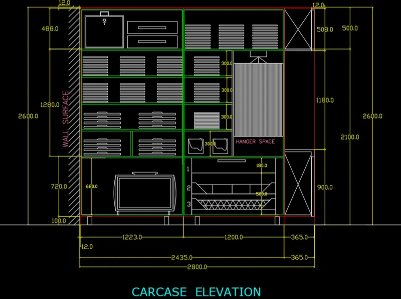
Carcase Elevation
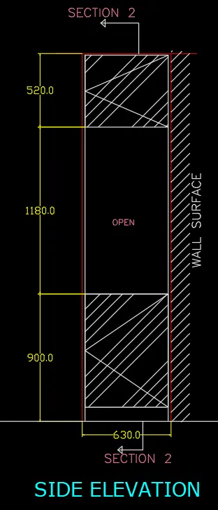
Side Elevation
Section 1
Section 2
Plan
Select LAYER PROPERTIES
Create LAYERS and select colour,Linetype and Lineweight properties to each layer.

Assign Layers to their respective objects
RESULT: -
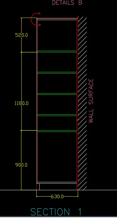
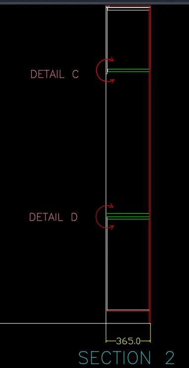
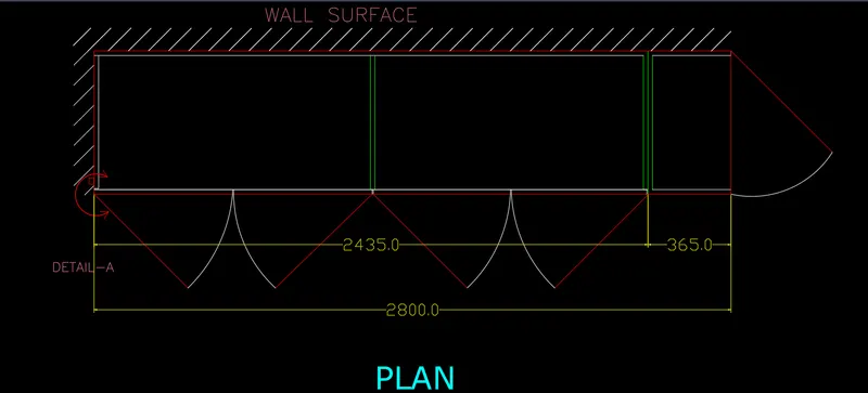
2Q]
AIM: -
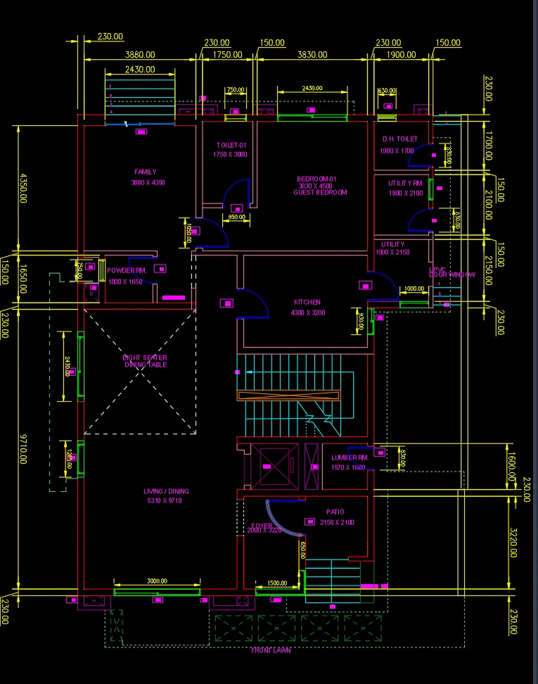
Draw the floor plan with the proper drafting tools.
Insert Text
Insert Dimensions
Use Layers
PROCEDURE: -
Set the units to DECIMAL using UNITS command
Set the lower limit and upper limit of the screen using LIMITS command
Choose the Construction line command
Draw a vertical line and horizontal line. The two lines intersects and this point is the starting point.
Start from left and go to right.
Select the OFFSET command with offset distance 230MM for External wall thickness
And internal wall thickness of 150mm
Choose Line command to draw rooms as per the given sizes in figure.
After drawing all rooms
By using TRIM command, trim the unnecessary lines
Draw staircase with size of Tread- 300mm and Riser- 150mm.
Select QLEADER command and show the direction of the stairs
Draw lift.
Provide Doors and windows of size
W1= 2430* 1200MM
W2= 3000*1200MM
W3= 930*1200MM
W5= 1265*1200MM
W9= 830*1200MM
W10= 2150*1200MM
D1= 1250*2000MM
D2= 1050*2000MM
D3= 950*2000MM
D4= 1050*2000MM
D5= 830*2000MM
V1= 750*500MM
V2= 630*500MM
SD3= 2430*2000MM
Draw Front Lawn.
Select LAYER properties dialogue box
Create New Layers
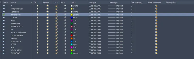
Select different COLOUR to each layer created.
Set External walls as current layer IN LAYER PROPERTIES and select all External walls
Set Internal walls as current layer and select all Internal walls.
Do this process for all created Layers.
Assign Linetype according to the drawing.
Select ANNOTATE
Use Dimensions tools
Use DIMLINEAR command and then select DIMCONTINUE command to mark the dimensions
Use DIMSPACE command to adjust the space between Linear dimansions
Select DIMBASELINE command to mark the distance from base to the respective object.
Mention all required dimensions. As shown in figure.
Select ANNOTATE
Use MTEXT command or select Multiline text tool or Single Line text tool to annotate text wherever required and as per in given figure.
RESULT: -
3Q]
AIM: -
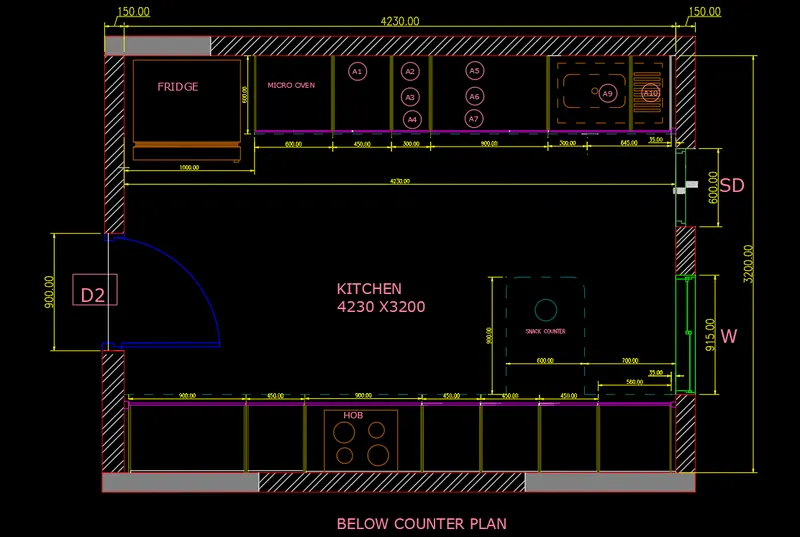
Create a Kitchen Layout
Use proper dimension techniques to dimension the kitchen layout
PROCEDURE: -
Choose command: UN for drawing units
Set length type to Decimal.
Choose Line command
Draw walls of thickness 150mm.
Use Fillet command and trim the corners perfectly
Assume sizes of Door= 900mm
Window = 915mm
Slide door= 600mm
Consider inner dimensions of kitchen as length= 4230mm and width = 3200mm
Draw BELOW COUNTER PLAN of Kitchen.
As per given figure draw all cabins and electric appliances in kitchen.
Use HATCH command to hatch the walls.
Select ANNOTATE
Use Dimensions tools
Use DIMLINEAR command and then select DIMCONTINUE command to mark the dimensions
Select DIMBASELINE command to mark the distance from base to the respective object.
Mention all required dimensions. As shown in figure.
Select ANNOTATE
Use MTEXT command or select Multiline text tool or Single Line text tool to annotate text wherever required and as per in given figure.
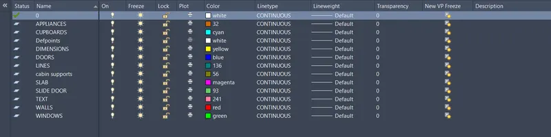
Select LAYER PROPERTIES
Create LAYERS and assign colour properties to each layer.
Assign Linetype according to the drawing.
RESULT: -
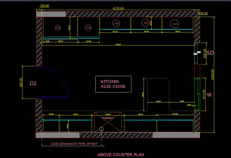
Now draw ABOVE COUNTER PLAN
Choose Line command
Draw walls of thickness 150mm.
Use Fillet command and trim the corners perfectly
Assume sizes of Door= 900mm
Window = 915mm
Slide door= 600mm
Consider inner dimensions of kitchen as length= 4230mm and width = 3200mm
Draw BELOW COUNTER PLAN of Kitchen.
As per given figure draw all cabins and electric appliances in kitchen.
Use HATCH command to hatch the walls.
Select ANNOTATE
Use Dimensions tools
Use DIMLINEAR command and then select DIMCONTINUE command to mark the dimensions
Select DIMBASELINE command to mark the distance from base to the respective object.
Mention all required dimensions. As shown in figure.
Select ANNOTATE
Use MTEXT command or select Multiline text tool or Single Line text tool to annotate text wherever required and as per in given figure.
Select LAYER PROPERTIES
Create LAYERS and assign colour properties to each layer.
Assign Linetype according to the drawing.
RESULT: -
4Q]
AIM: -
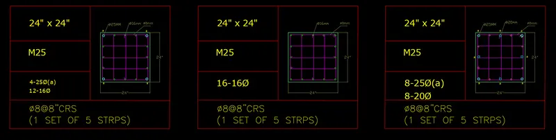
Sketch the column details as shown in figure.
Insert dimension and text.
PROCEDURE: -
Choose command: UN for drawing units
Set length type to Engineering.
Select Line command
Using Line draw table of 2 columns and 4 rows
Draw columns
Draw bars arrangement schedule as per drawing.
Choose Command: ST for text style
Create new style with
Font name: romans.shx
Justify: left
and set current
Choose command: MTEXT for Multi line text
Draw box on screen
Set justification to Left in Text editor
Select ANNONTATE in Ribbon
Under TEXT dialogue box
Choose Multiline Text tool
Using MTEXT write the schedule in the table.
In the Text Editor, under INSERT tools select SYMBOL option for bar diameter notation.
In the Text Editor, use SPELL CHECK tool for any spell checks.
Select ANNONTATE in Ribbon
Under DIMENSION dialogue box
Choose DIMDIAMETER command to mark bars diameter dimension.
Select DIMLINEAR command to mark column dimensions.
Use QLEADER command to show up the text details of the object drawn.
Using TRIM command trim the extended lines.
Select LAYERS PROPERTIES.
List down all Layers required to assign to objects
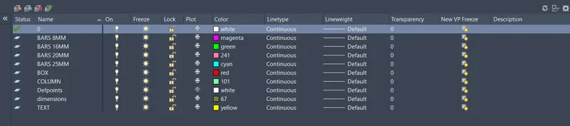
Assign colours to all mentioned layers
Assign Layers to respective objects drawn.
RESULT: -
5Q]
AIM: -
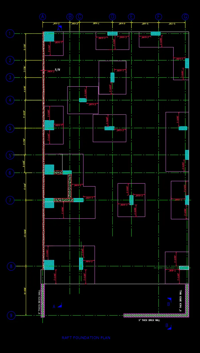
Draw raft layout as shown in the figure.: RAFT FOUNDATION PLAN
Use Layers.
Use proper dimension techniques to dimension the RAFT Layout
PROCEDURE: -
Choose command: UN for drawing units
Set length type to Engineering.
Select command XLINE
Draw Base line Horizontal and vertical line lines.
Choose LineType command and change the line type to 1DASH to mark gridlines.
Select OFFSET command to draw gridlines as per the figure given.
Label Numbers to the drawn gridlines as per the figure.
After marking the gridlines in both X -direction and Y- direction,
Plot the column position as per the given size.
Column sizes given in the figure are:
24”x24”, 9” x 24”, 9” x 18”, and 9’ x 24”.
Sketch the footing layout with provided details to these columns.
Draw Brick walls, Retaining walls.
Using HATCH command hatch the area wherever required.
Select ANNONTATE in Ribbon
Under TEXT dialogue box
Choose Multiline Text tool
Using MTEXT write the details and labells of centrelines and columns.
In the Text Editor, use SPELL CHECK tool for any spell checks.
Select ANNONTATE in Ribbon
Under DIMENSION dialogue box
Select DIMLINEAR command to mark column dimensions, and then
Select DIMCONTINUE command to mark the distances between centrelines.
Select ANNONTATE in Ribbon
Choose CENTERLINE command to mark centreline for Brickwall
Select LAYERS PROPERTIES.
List down all Layers required to assign to objects
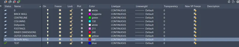
Assign colours to all mentioned layers
Assign Layers to respective objects drawn.
RESULT:-