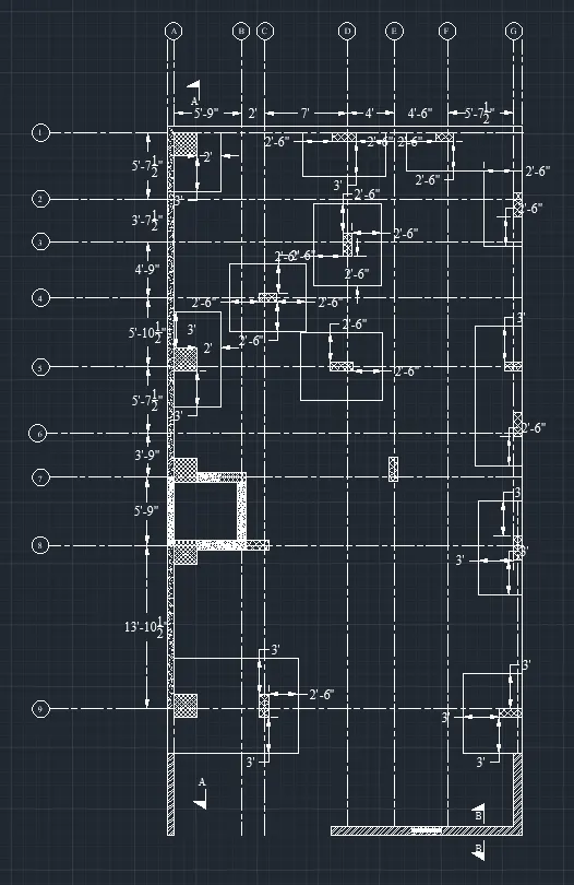
Creating a Wardrobe detailed drawing, Floor Plan, Kitchen Layout and Column Detail using AutoCad
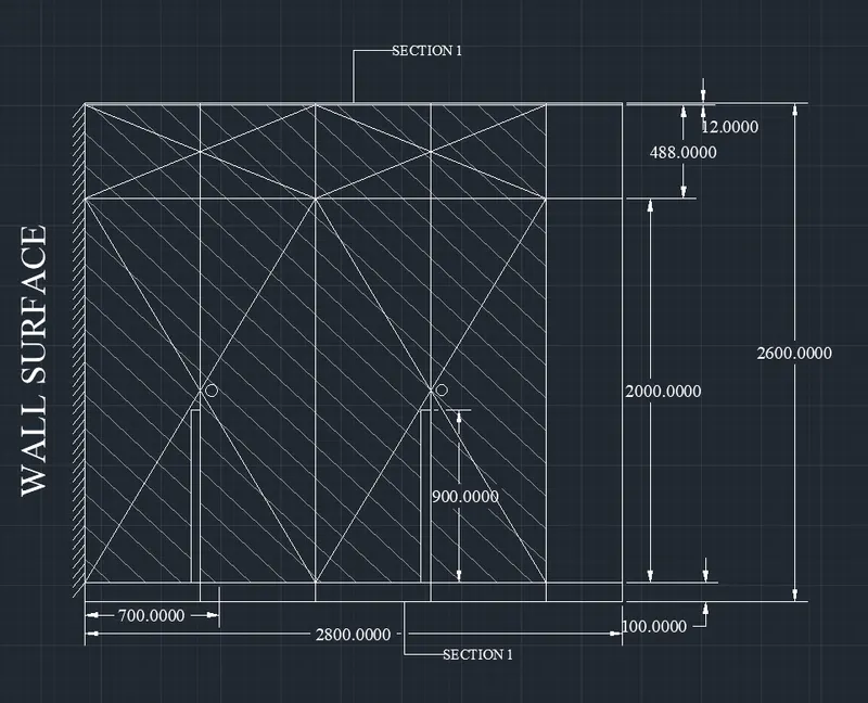
AIM:TO Draw the elevation and details of a wardrobe as shown in figure below.After sketching and to provide the dimensions and text with use of layers
- PROCEDURE:
- STEP 1:
- Units are set to be in "Engineering" and in ''mm''
- Limits and Limitmax are also set
- Click zoom and enter ''all''
2.STEP 2:
- In the command line type rec @2800,2600
- In the command line type offset
- Offset from the top of dimensions 12 and 488mm.
3.STEP 3.
- In the command line type offset
- Create the offset from the side at a distance of 608.75 and 365
4.STEP 4.
- In the command bar type line by increasing thetransperancy to create the wall surface
- By using the hatch give scale 20
- In the command line type q leader to mention the annotations
- RESULT
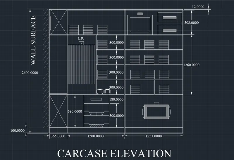
- AIM: To draw the carcase elevation as the shown in the figure
- PROCEDURE:
- In the command line type ''rec'' and provide dimensions 2800 X 2600
- Take the offset of 230m of exterior wall and 150mm in the interior wall
- Start the work from the bottom to top left to right as per provided dimensions
- First take offset from 100mm from bottom to top 680mm,300mm,300mm,300mm,488mm as shown in the drawing
- Draw the interior blocks by using the line command then place as per given drawing
- Next the apply the transparency unit for all blocks for all the blocks placed
- Give proper dimensions as per ''DIMCONTINUE'' command
- Take the text command write and dit the text applied
- RESULT
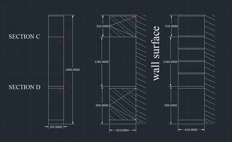
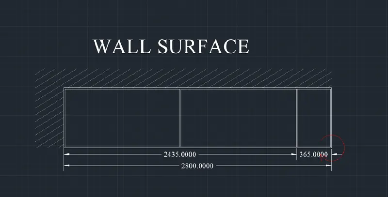
- AIM:To draw the elevation as per shown in the drawing
- PROCEDURE:
- Draw a rectangle of dimension of 630 X 2600 mm
- Take a offset of 100 mm from the bottom side and then take a offset of 900mm ,1180mm and 520mm
- Take the offset of 20mm from both side and draw a wall suface area
- Give the proper dimension using''DIM''
- Select the text command and write the text whenever necessary
- In Section 2 draw rectangle of 365 X 2600mm then stafrt work from top
- Take the offset from 100mm and then 1180mm and 520mm
- Take the offset of 20mm and then draw a wall surface
- Give the proper dimension usin ''DIM''
- Take the text command and write the text wheereever required
- RESULT
- AIM: To draw a PLAN
- PROCEDURE:
- Draw a rectangle of 2800 X 630 mm
- Take the offset of 20mm from all the side and draw the wall surface
- Give the proper dimension usin ''DIMCONTINUE''
- Take the text command and write and edit the text wherever required
- RESULT
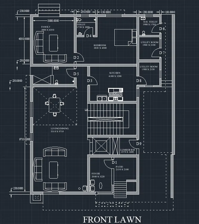
- AIM: To draw the floor plan as per shown diagram
- PROCEDURE:
- STEP 1:
- First set the unit command in ''Enginneering'' and ''mm''
- Set the limitmax and limits and the zoom and enter all
- Import the pdf file into current drawing
- scale it properly
- STEP 2:
- Creation of external wall and internal wall
- Set the wall layer as the current layer
- Take the construction line and set the vertical and horizontal line
- Take the dimension reference from the drawing
- STEP 4:
- Create the doors, windows and set the dimension and text
- Take the door and windows from autocad design centre ''ADS'' and take the appropriate scale
- For staircase draw the line and take the offset of 300mm trade and riser 150mm
- RESULT
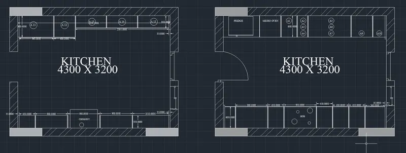
- AIM: To create the kitchen layout
- PROCEDURE
- Draw the rectangle by entering ''REC''
- Select the first point and give the offset of 4300 x 3200
- Take the offset command and give the offset of 230mm in the outer section
- For windows take the offset of window size and make offset from the external wall and trim the extra wall
- Creation of doors and hatches
- For doors take take the shortcut key ctrl+3 adjust the size of door as per requiremewnt and put it wherever required
- Now give the appropriate dimension
- RESULT
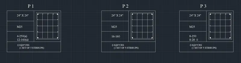
- AIM:To sketch the column detail
- PROCEDURE
- First set the units in 'Engineering'' and ''mm''
- Set the limit as per requirement
- Take the rectangle of ''24x 24'' by using ''REC''
- Take the offset of 2'' from all the side
- For Creating the shoulder bar and take the circle with tangent , tangent and radious and take the two tangent point and give the radious
- For creation of strips take the line command mark a line command from the start point and end of the circle bar
- Write the alphabet for indicating the size of bar
- Now take the command mtext give the base point for the text
- Give the size ,height,type of text
- RESULT
- AIM: To draw the draft layout using the autocad
- PROCEDURE:
- Set the units in ''ARCHITECTURAL'' and in ''inches''
- Import the pdf into autocad and ensure the missing dimension
- Select the all columns go to the copy and select the base pointdraw to side for place it
- Draw the footinhg and walls of resp. dimension
- At the bottom draw the wall of 9'' inch thickness
- Now take the hatch command and mark the hatch in all columns
- Take the hatch markin all close boundry of columns and wall
- Mark the grid line and select the centre kline 2
- Take the line command and select the centreline 2x
- Mark the gride from every centre of columns
- Create the text and dimension
- Take the circle comand draw the circle
- Now take the text command and give the appropriate height
- Now edit the text as per required it
- RESUL