Creating a Wardrobe detailed drawing, Floor Plan, Kitchen Layout and Column Detail using AutoCad
Aim:-
The elevation and details of a wardrobe .After sketching, the drawing to provide dimensions and text with the use of layers. And proper text styles and dimension methods too.
Introduction:-
setting the standards:- in the following topics,
We will learn about the standard setting used in autocad before starting the drafting process.
Unit command: units command is used to control the precision and display formats for coordinates,
Distance and angle
- command: units press enter
- short key: un press enter
- Access from: menubar >format>units
- set units decimal ,scale in milimeter and press ok.
- To save that setting.
Procedure:-
line command: type the line command
Trim command :- trim command is used to delete the unwanted part of an object.
command : trim and press enter
shortcut key : tr and press enter
offset command: offset command is used to create concentric circles,parraller lines and parallel curve from the existing curve the geomentry.
command: offset
shortcut key : o and press enter
ribbon menu: home>modify panel>offset
Hatch command:
Hatch commnd is used to fill an enclosed area or selected object eith a selected hatch pattern ,solid fill or a gradient fill.
command - hatch command
shortcut- h and press enter
dimension command:
linear dimension is used to measure and display the linear disrtance value of a line or between two points.
Linear dimension can be horizontal,vertical or alingned
Command: dimli and press enter
shortcut : dli and press enter
ribbon menu: annotate >dimension>linear
Access from: menu bar>dimension>linear
After the specifying the start and end points, the software prompts as below for more options.
Layer management:-
creates a layer with a default name . the new layer inherits the properties of the currently
selected layer in the layer list
set current - set current layer as the current layer.new object automatically created on the layer.
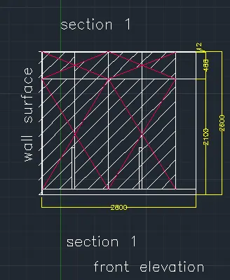
front elevation wardrobe:
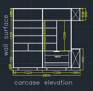
carcase elevation:-
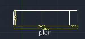
side elevation
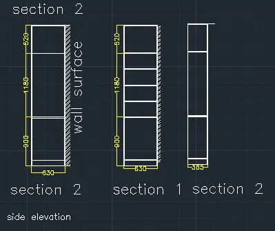
and final results:
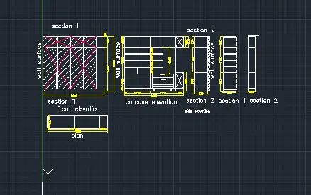
Aim:
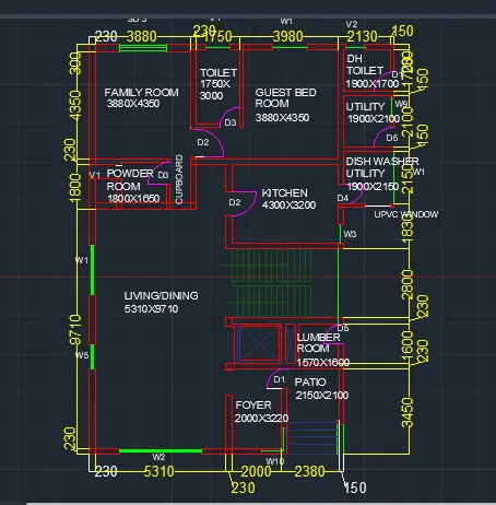
The floor plan proper drafting tools to sketch the plan.
Introduction:-
setting the standards:- in the following topics,
We will learn about the standard setting used in autocad before starting the drafting process.
Unit command: units command is used to control the precision and display formats for coordinates,
Distance and angle
- command: units press enter
- short key: un press enter
- Access from: menubar >format>units
- set units decimal ,scale in milimeter and press ok.
- To save that setting.
Procedure:-
line command: type the line command
Trim command :- trim command is used to delete the unwanted part of an object.
command : trim and press enter
shortcut key : tr and press enter
offset command: offset command is used to create concentric circles,parraller lines and parallel curve from the existing curve the geomentry.
command: offset
shortcut key : o and press enter
ribbon menu: home>modify panel>offset
Hatch command:
Hatch commnd is used to fill an enclosed area or selected object eith a selected hatch pattern ,solid fill or a gradient fill.
command - hatch command
shortcut- h and press enter
dimension command:
linear dimension is used to measure and display the linear disrtance value of a line or between two points.
Linear dimension can be horizontal,vertical or alingned
Command: dimli and press enter
shortcut : dli and press enter
ribbon menu: annotate >dimension>linear
Access from: menu bar>dimension>linear
After the specifying the start and end points, the software prompts as below for more options.
Layer management:-
creates a layer with a default name . the new layer inherits the properties of the currently
selected layer in the layer list
set current - set current layer as the current layer.new object automatically created on the layer.
Draw construction line command xl for horizontal and vertical.
Drawing family room:
give an offset of 3880mm from the wall thickness and offset of 230mm for other side.
draw another offset of 4350mm from the 300mm wall thickness for drawing room.
Drawing toilet:
give an offset of 1750mm from the wall thickness and offset of 150mm for other side.
draw another offset of 3000mm from the 150mm wall thickness for drawing room.
Drawing guest room:
give an offset of 3830mm from the wall thickness and offset of 230mm for other side.
draw another offset of 4500mm from the 300mm wall thickness for drawing room.
Drawing guest room:
Take an offset of 2100mm downwards the wall of dh toilet
also offset the wall thickness of 150mm.
Drawing guest room:
Take an offset of 2150mm downwards the wall of dh toilet also offset the wall thickness of 150mm.
Drawing guest room:
From the left wall of dishawasher ulitily room,take an offset of 4300mm to the left and wall thickness of 230mm.
From the wall of guest bedroom draw an offset of 3200mm download and also wall thickness of 230mm.
extend the topwall of kitchen a distance a distance of 1462mm excluding wall thickness.
Drawing cupboard and powder room:
Take an offset of 1000mm for the cupboard the wall othickness of 150mm.
give an offset of 1800mm from the wall and also wall thicjness of 230mm
take offset of 1650mm for that wall to the bottom
Drawing living room:
give an offset of 9710mm from the wall thickness and offset of 230mm for other side.
draw another offset of 53100mm from the 300mm wall thickness for drawing room.
Drawing foyer room:
give an offset of 2000mm from the wall thickness and offset of 230mm for other side.
draw another offset of 3220mm from the 230mm wall thickness for drawing room.
Drawing patio room:
give an offset of 2100mm from the wall thickness and offset of 230mm for other side.
draw another offset of 2150mm from the 300mm wall thickness for drawing room.
Aim:-
The Kitchen Layout as proper dimension techniques to dimension the kitchen layout. All dimensions are in mm.
Introduction:-
setting the standards:- in the following topics,
We will learn about the standard setting used in autocad before starting the drafting process.
Unit command: units command is used to control the precision and display formats for coordinates,
Distance and angle
- command: units press enter
- short key: un press enter
- Access from: menubar >format>units
- set units decimal ,scale in milimeter and press ok.
- To save that setting.
Procedure:-
line command: type the line command
Trim command :- trim command is used to delete the unwanted part of an object.
command : trim and press enter
shortcut key : tr and press enter
offset command: offset command is used to create concentric circles,parraller lines and parallel curve from the existing curve the geomentry.
command: offset
shortcut key : o and press enter
ribbon menu: home>modify panel>offset
Hatch command:
Hatch commnd is used to fill an enclosed area or selected object eith a selected hatch pattern ,solid fill or a gradient fill.
command - hatch command
shortcut- h and press enter
dimension command:
linear dimension is used to measure and display the linear disrtance value of a line or between two points.
Linear dimension can be horizontal,vertical or alingned
Command: dimli and press enter
shortcut : dli and press enter
ribbon menu: annotate >dimension>linear
Access from: menu bar>dimension>linear
After the specifying the start and end points, the software prompts as below for more options.
Layer management:-
creates a layer with a default name . the new layer inherits the properties of the currently
selected layer in the layer list
set current - set current layer as the current layer.new object automatically created on the layer.
Below counter plan:
Drawing wall : Draw a rectangle of 4300mm and 3200mm draw offset 230mm as wall thickness towards outside.
Drawing left cabinet anf fridge:
fridge is drawn as almost side by rectabgle tool.
take of offset 1000 and starting slab showing cabinet below offset 600mm for microwave oven
give offset of 20mm to show the partition of cabinet below.
agine offset 600, 450, 300, 900,715 and 35.
Drawing right cabinet and hob:
give 35mm offset from the left create a hinge
for width of cabinet give 600mm offset , give 20mm inside and 10mm oddset for thickness.
from 35mm give 900mm offset .
and again offset of 450mm ,900,450,,450,450,630 and 35 offset.
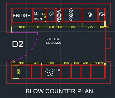
above left side counter:
give 35mm offset from the left create a hinge
for width of cabinet give 600mm offset , give 20mm inside and 10mm offset for thickness.
from 35mm give 965mm offset .
and again offset of 2665 and 35 offset.
Text and dimension :
Dimension all the object by dimension tool in the toolbar
For text select multiline text size 75mm style romans.shx.command st.
write all text in respective places like fridge,hab,cabinet,number etc.
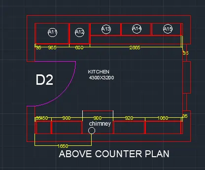
and final result:
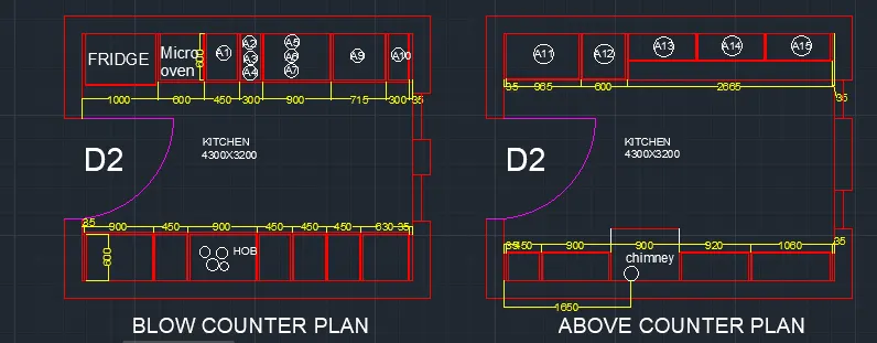
Aim:
The column Insert dimensions and text to the bar sizes from the schedule.
Procedure:
Creating table:
- Create the rectangle angle of 48'x48' , explode it.
- Divide the column and again divide one18' using offset command
- Create raw at top and bottom of 2' and 4' respectively by offset command.
- Command offset select the top line and give distance as 2' again command o select the bottom line and give offset distance as 4'.
- Trim off the unecessary lines.
Extering text:-
- Enter the text in the table by using singeline text from the text drop down menu specify the point of text specify text height as 8" and angle as 0 degree .
- "Terrace of mumty" give text angle as 90 degreeand type the text.
- after entering the text , right click and select properties- then list of properties will be displayed
- ensure the text height is 8" and make justify as left
- To change the style of text command "ST" a dialouge box apperas and select the font name as "romans.shx"
- Then insert all the text or copy the text created and edit it to the required text in respective rows and columns
- Give the healding as column shedule:
Drawing the column section:
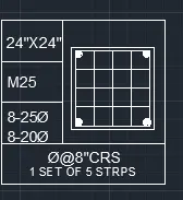
- Draw a rectangle of sixe 24""x24" by using rec command
- Draw the column outline after a cover of 40mm i.e 0.5" by offest command
- and draw the circle reinforcement command "c" click on tan tan radius on the command box .
- And use the copy command and draw the again column
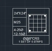
p2.
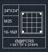
p3.
Aim:- The drw Raft Layout
Introduction:-
setting the standards:- in the following topics,
We will learn about the standard setting used in autocad before starting the drafting process.
Unit command: units command is used to control the precision and display formats for coordinates,
Distance and angle
- command: units press enter
- short key: un press enter
- Access from: menubar >format>units
- set units decimal ,scale in milimeter and press ok.
- To save that setting.
Procedure:-
line command: type the line command
Trim command :- trim command is used to delete the unwanted part of an object.
command : trim and press enter
shortcut key : tr and press enter
offset command: offset command is used to create concentric circles,parraller lines and parallel curve from the existing curve the geomentry.
command: offset
shortcut key : o and press enter
ribbon menu: home>modify panel>offset
Hatch command:
Hatch commnd is used to fill an enclosed area or selected object eith a selected hatch pattern ,solid fill or a gradient fill.
command - hatch command
shortcut- h and press enter
dimension command:
linear dimension is used to measure and display the linear disrtance value of a line or between two points.
Linear dimension can be horizontal,vertical or alingned
Command: dimli and press enter
shortcut : dli and press enter
ribbon menu: annotate >dimension>linear
Access from: menu bar>dimension>linear
After the specifying the start and end points, the software prompts as below for more options.
Layer management:-
creates a layer with a default name . the new layer inherits the properties of the currently
selected layer in the layer list
set current - set current layer as the current layer.new object automatically created on the layer.
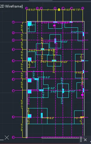
Drawing the grid lines:-
Draw an verical line with construction line xl-v
offset the vertical by offset command with offset command 5'9",2',7,4',4'6",5'-7 1/2',.
Draw an verical line with construction line xl-h
offset the vertical by offset command with offset command 5'-7 1/2",3'-7 1/2",4'9",5'10.5",5'7.5",5'9",13'10.5" & 10'4.5"
mark the gorizontal line from 1 tto 9
mark the vertical from a to g
draw the bottom thickness 9" and upper grid line 4.5"
drawing column and rectangle box.