Creating a Wardrobe detailed drawing, Floor Plan, Kitchen Layout and Column Detail using AutoCad
ANSWERS:
General Notes:
To Cancel Selected Command Press “ESC”
To Invoke Previously Selected Command Press “ENTER”
+X represents Positive X Direction
+Y represents Positive Y Direction
-X represents Negative X Direction
-Y represents Negative Y Direction
WARDROBE
SETUP: Open AutoCAD select Advanced Setup , Use a WIZARD then select Unit of Measurement as Decimal, Precision 0.0,Insertion Scale as Millimetres.
LIMITS Specify 0,0 Enter Specify 5000,5000
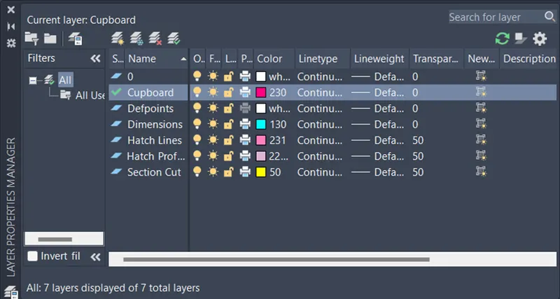
LAYER: Create LAYERS and Specify Respective Colour and Properties
FRONT ELEVATION
LAYER: Wardrobe
RECTANGLE: Create a Rectangle of 2800x 2600
EXPLODE: Explode the Rectangle to make all sides into Individual lines
OFFSET - Specify an Offset of 12 and Create offset in inward Direction, Press Enter and Invoke offset again Whenever required to repeat the same tool,
Specify 100 and Click Bottom Line and Drag Upward Direction
Specify 488 and Click Bottom Line and Drag Downward Direction
specify 365, Click right outer edge of the wardrobe and click on the inside the Rectangle
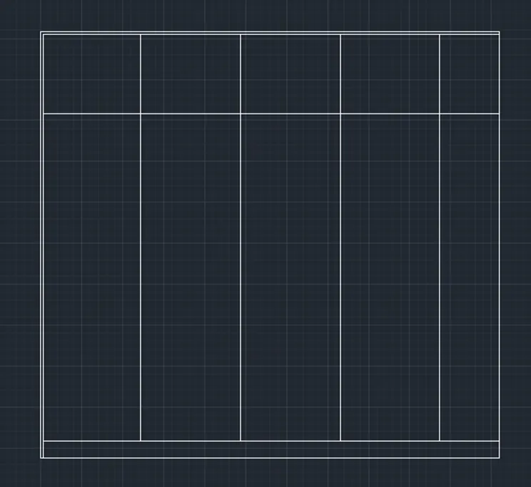
LINE: Create 4 Vertical Lines at Equal Distance from Remaining Space
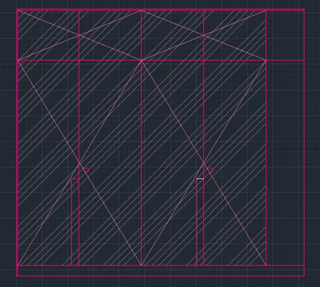
POLYLINE: Create diagonal lines across all individual Rectangle as Shown in Figure
TRIM: Remove all unwanted lines which are Lying in between rectangles
CIRCLE: specify radius of circle as 20. Create Near the Handle
RECTANGLE: Create a Rectangle of 70x 835 place it near the Door Edge as Shown in figure
COPY: Copy the Rectangle and Circle to all door corners
RECTANGLE: Create a Rectangle of 200x 2600place it near the Left Edge of the Elevation
LAYER: Hatch Lines
HATCH: Transparency: 50
*Select ANS13 pattern, Hatch Scale :15 select the door Portion to hatch
*Select: JIS_LC_20 pattern, Hatch Scale :3.5, Hatch Rectangle created on the left edge of Wardrobe as wall Surface and Erase Boundary Rectangle around the Hatch
LAYER: Dimensions
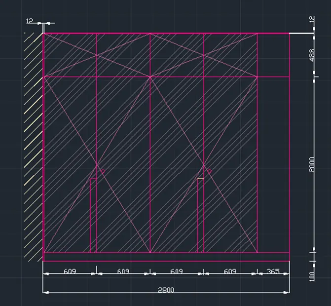
DIMLENIAR: Select and Place the Desired Dimensions, Represent all the Dimensions
MTEXT: Create a Text Box and Enter the sample text, Copy and Paste multiple in Desired Position and desired angle with Desired Size
EDIT TEXT (ED): Edit the MTEXT Created and Pasted and Type the actual name, size, rotation angle
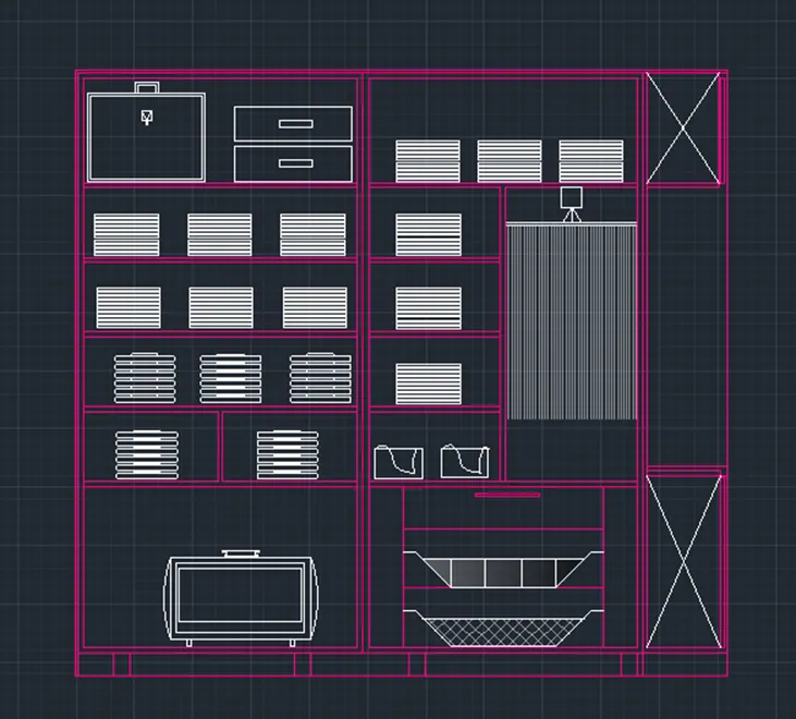
CARCASE ELEVATION
LAYER: Wardrobe layer
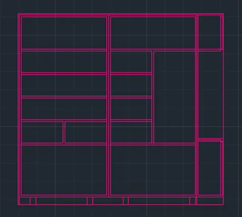
RECTANGLE : Create a Rectangle of 2800x 2600
EXPLODE: Explode the Rectangle to make all sides into Individual lines
- Draw a rectangle, using REC command, Specify the first point outside the top left corner of the wardrobe, and specify the second corner as the bottom right corner of the wardrobe.
- Select the Hatch tool, by entering H command, select JIS_LC_20 pattern, and set the hatch scale as per requirement, pick the point as the rectangle created earlier. Press Esc.
OFFSET - Specify an Offset of 12 and Create offset in inward Direction, Press Enter and Invoke offset again Whenever required to repeat the same tool,
Specify 100 and Click Bottom Line and Drag Upward Direction
Specify 488 and Click Bottom Line and Drag Downward Direction
specify 1223 Click left inner edge of the wardrobe and click on the inside.
specify a distance of 1200, select the last offset line and click towards right.
specify a distance of 20, select the last offset lines and click to provide thickness of the wardrobe portions as per the given diagram.
specify a distance of 508, select the top edge of the wardrobe and click downwards.
specify a distance of 1260, select the last offset line and click downwards.
specify a distance of 20, provide thickness to the last two offset lines.
specify a distance of 300, select the last offset line and click downwards.
specify a distance of 20, provide thickness to the previous offset line.
specify a distance of 300, select the last offset line and click downwards.
specify a distance of 20, provide thickness to the previous offset line.
specify a distance of 300, select the last offset line and click downwards.
specify a distance of 20, provide thickness to the previous offset line.
specify a distance of 300, select the last offset line and click downwards.
specify a distance of 20, provide thickness to the previous offset line.
TRIM: Remove all unwanted lines which are Lying in between rectangles
DEVIDE : divide the sections wherever Required
OFFSET - specify 20 and offset the partition lines offset for 20
LAYER: Hatch Lines
LINE: boxes with diagonal lines at the top right corner and bottom right corner of the wardrobe with the Transparency :50.
BRIEFCASE
LAYER: Objects, Transparency 25
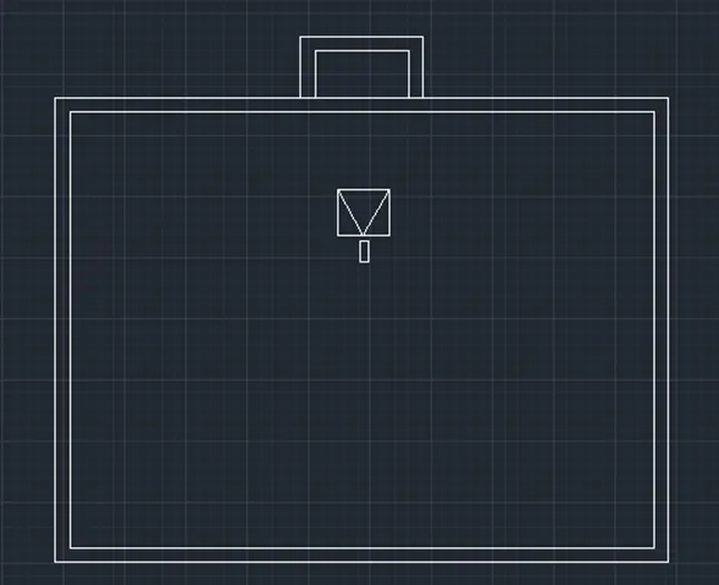
RECTANGLE: Create a Rectangle of 500x 380
OFFSET: Specify an Offset of 12 and Create offset in inward Direction
LINE: Create the Handle and Lock by using Line tool
CHEST OF DRAWERS
LAYER: Objects, Transparency 25
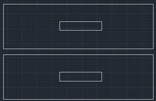
RECTANGLE: Create a Rectangle of 500x 150
OFFSET: Specify an Offset of 20 and Create offset in inward Direction
RECTANGLE: Create a Rectangle of 140x 30, Place it inside Center of the rectangle created previously
COPY: Copy and Paste the object above original
CLOTHS
LAYER: Objects, Transparency 25
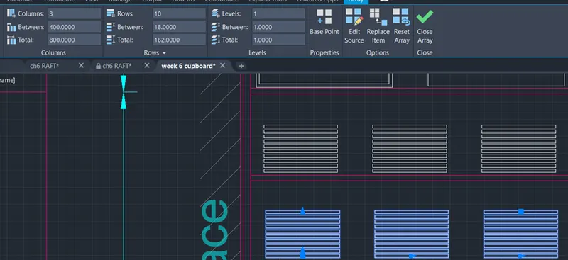
RECTANGLE: Create a Rectangle of 270x 12
ARRAY : Select object as Rectangle created, Rows as 10 and Columns as 1 Paste it individually,
Select object as Previously arrayed object , Modify as 10 Rows Between 18, 3 COLUMNS Between 400 Place it in 3 Compartments as per the Drawing,
SHIRTS
LAYER: Objects, Transparency 25
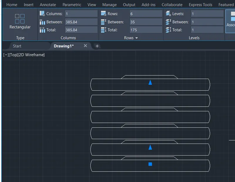
RECTANGLE: Create a Rectangle of 250x 25
ARC: Create arc on both 25mm sides and Trim unwanted lines
LINE: To draw the Collar of Shirt, Specify first point at a distance of 75 mm from Left upper Corner of Rectangle
Specify Next point as 12<45degree
Specify Next point as 100 towards right
Specify Next point as 12<225degree
JOIN : Select all Objects and Press J
ARRAY: Select object as Joined objects, Rows as 6 at 35mm and Columns as 1 at 35
COPY: Select arrayed objects and Paste it at Desired Locations
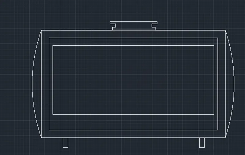
SUITCASE
LAYER: Objects, Transparency 25
RECTANGLE: Create a Rectangle of 600x 350
OFFSET: Specify an Offset of 25 and Create offset in inward Direction
EXPLODE: explode the offseted rectangle
OFFSET: Specify an Offset of 12 and Create offset in inward Direction
Specify an Offset of 50 and Create offset from top and bottom in inward Direction
ARC: Create arc on both left and Right side from 3 point arc
RECTANGLE: Create a Rectangle of 15x 30 and Place it Below the Rectangle
COPY: Copy and Paste Previously created rectangle and paste it in opposite side
RECTANGLE: Create a Rectangle of 235x 15 and Place it over the Rectangle at Center and as Handle
Repeat the Rectangle and Create 250 x 10 and place it over previously created rectangle
TRIM: Trim Unwanted lines
SIDE ELEVATION
LAYER: Wardrobe layer
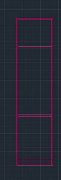
RECTANGLE : Create a Rectangle of 630x 2600
EXPLODE: Explode the Rectangle to make all sides into Individual lines
OFFSET - Specify an Offset of 12 and Create offset in inward Direction, Press Enter and Invoke offset again Whenever required to repeat the same tool,
specify an Offset distance of 100, select the bottom line of the rectangular figure, click on the inside of the rectangle to offset.
specify an Offset distance of 800, select the last offset line of the figure, click on the inside of the rectangle to offset.
specify an Offset distance of 1180, select the last offset line of the figure, click on the inside of the rectangle to offset.
specify an Offset distance of 20, select the previous offset lines, click downwards to offset.
TRIM: Remove all unwanted lines which are Lying in between Lines
LAYER: Hatch Lines
POLYLINE : • Draw diagonal lines at the top and bottom sections as shown in the given diagram. Transparency 50
Create the Hatch for WALL SURFACE as done previously
LAYER: Hatch Lines
HATCH : Transparency : 50
*Select ANS13 pattern, Hatch Scale :15 select the door Portion to hatch
*Select: JIS_LC_20 pattern, Hatch Scale :3.5, Hatch Rectangle created on the left edge of Wardrobe as wall Surface and Erase Boundary Rectangle around the Hatch
LAYER: Dimensions
DIMLENIAR: Select and Place the Desired Dimensions, Represent all the Dimensions
MTEXT: Create a Text Box and Enter the sample text, Copy and Paste multiple in Desired Position and desired angle with Desired Size
EDIT TEXT (ED): Edit the MTEXT Created and Pasted and Type the actual name, size, rotation angle
SECTION-1
LAYER: Dimensions
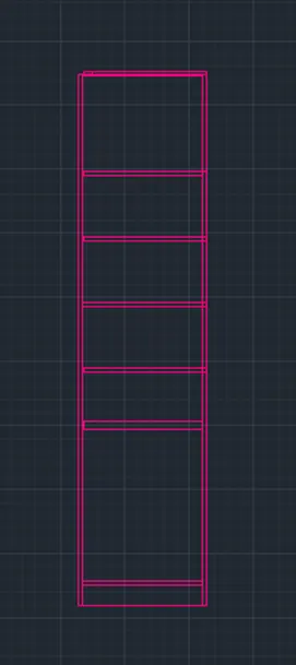
COPY: Select the Side Elevation and Copy , then Paste it Beside the Side Elevation
TRIM : trim 20mm offset Line at Top, Hatch Lines,
EXTEND: Extend the Bottom 100mm offset line(first) through 20mm horizontally
TRIM : Trim the Vertical Line Lying between bottom 100mm distance
LINE: Create a Line of 100mm at a Distance of 100 from left end
OFFSET : Specify 12, offset from top towards inward(horizontally)
Specify 20 from, offset from Previous towards inward(horizontally)
OFFSET : specify an Offset distance of 300, offset from last offset line, click upwards four times to offset(Horizontally)
specify an Offset distance of 20, offset from previous offset lines individually, click downwards to offset and provide thickness to the shelves.
Specify 20, offset from Left interior Offseted line towards inward(vertically)
TRIM: trim all the lines lying between previously created Vertical offset line and Unneccessary lines between horizontally created offsets
LAYER: Hatch Lines
HATCH : Transparency : 50
*Select ANS13 pattern, Hatch Scale :15 select the door Portion to hatch
*Select: JIS_LC_20 pattern, Hatch Scale :3.5, Hatch Rectangle created on the left edge of Wardrobe as wall Surface and Erase Boundary Rectangle around the Hatch
LAYER: Dimensions
DIMLENIAR: Select and Place the Desired Dimensions , Represent all the Dimensions
MTEXT :Create a Text Box and Enter the sample text, Copy and Paste multiple in Desired Position and desired angle with Desired Size
EDIT TEXT (ED): Edit the MTEXT Created and Pasted and Type the actual name, size, rotation angle
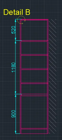
ARC: select the 3 Point option, and draw an arc as shown in the given diagram at adequate positions.
LINE: Select the Line tool from the ribbon and draw arrows at the ends of the above arc.
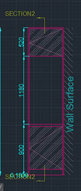
SECTION-2
LAYER: Wardrobe layer
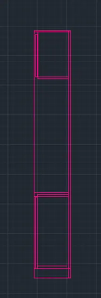
RECTANGLE : Create a Rectangle of 365x 2600
EXPLODE: Explode the Rectangle to make all sides into Individual lines
OFFSET - Specify an Offset of 12 and Create offset in inward Direction, Press Enter and Invoke offset again Whenever required to repeat the same tool,
specify an Offset distance of 100, select the bottom line of the rectangular figure, click on the inside of the rectangle to offset.
specify an Offset distance of 800, select the last offset line of the figure, click on the inside of the rectangle to offset.
specify an Offset distance of 1180, select the last offset line of the figure, click on the inside of the rectangle to offset.
specify an Offset distance of 20, select the previous offset lines individually, click downwards to offset and privide thickness to the shelves.
TRIM: trim all the lines lying between previously created Vertical offset line and Unnecessary lines between horizontally created offsets
LAYER: Dimensions
DIMLENIAR: Select and Place the Desired Dimensions, Represent all the Dimensions
MTEXT: Create a Text Box and Enter the sample text, Copy and Paste multiple in Desired Position and desired angle with Desired Size
EDIT TEXT (ED): Edit the MTEXT Created and Pasted and Type the actual name, size, rotation angle
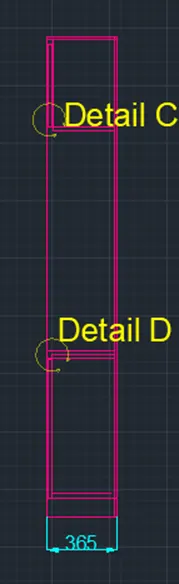
ARC: select the 3 Point option, and draw an arc as shown in the given diagram at adequate positions.
LINE: Select the Line tool from the ribbon and draw arrows at the ends of the above arc.
PLAN
LAYER: Cupboard
XLINE : Create Vertical Lines from Front Elevation for Side and Middle Lines
Create Vertical Line as a BASE line
OFFSET: create Offset for Middle line on both side for 10 mm (Vertically)
*Specify 20mm for Line created on right side and offset on both side (Vertically)
*Specify 20mm from Baseline (Horizontally)
* Specify 630mm from Baseline (Horizontally)
*Specify 20mm from top (Previously created offset) (Horizontally)
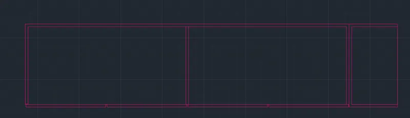
RECTANGLE: Create a Rectangle of 150x630 and place it on left side
Create a Rectangle of 2600x150 and place it on top
TRIM: TRIM unwanted Lines
HATCH: Transparency: 50
*Select ANS13 pattern, Hatch Scale :15 select the select previously created Rectangles to hatch
TRIM: TRIM Outer Rectangle outside the Hatch Portion
ARC: create the arc on Door Portion by using 3 point Arc Tool, and Bisect the lines to Create Door and Trim remaining unwanted position
LAYER: Dimensions
DIMLENIAR: Select and Place the Desired Dimensions, Represent all the Dimensions
MTEXT: Create a Text Box and Enter the sample text, Copy and Paste multiple in Desired Position and desired angle with Desired Size
EDIT TEXT (ED): Edit the MTEXT Created and Pasted and Type the actual name, size, rotation angle
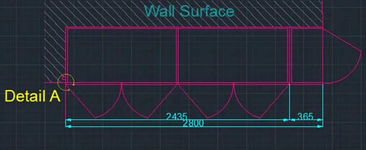
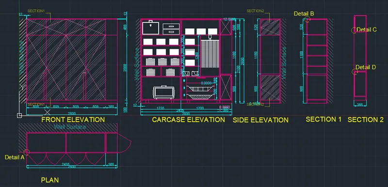
RESULT:
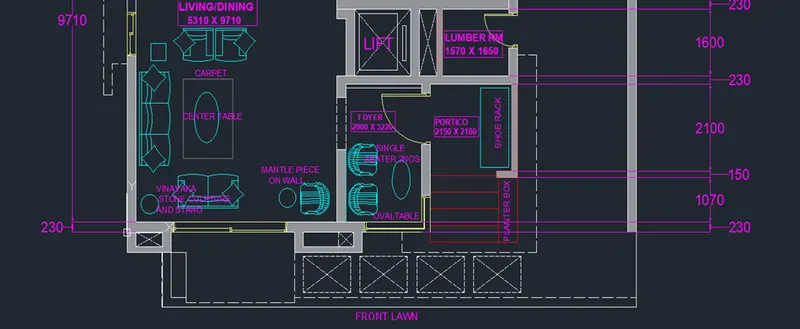
FLOOR PLAN
SETUP: Open AutoCAD select Advanced Setup , Use a WIZARD then select Unit of Measurement as Decimal, Precision 0.0,Insertion Scale as Millimetres.
LIMITS, Specify 0,0 Enter Specify 5000,5000
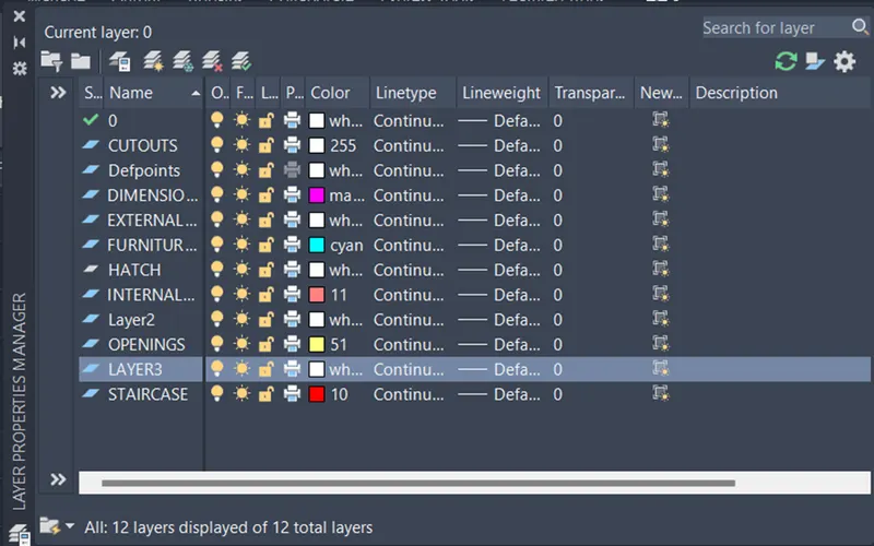
LAYER: Create LAYERS and Specify Respective Colour and Properties
WALL:
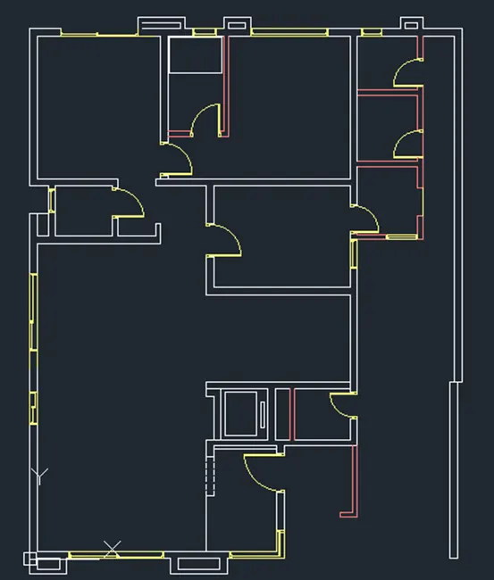
XLINE : Create Horizontal and Vertical lines
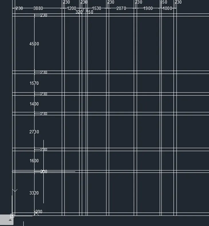
OFFSET : Create Vertical OFFSETS at a Distance of 230,3880,230,1200,230,320,1530,230,2070,230,1900,150,1000,230 in X Direction
Create Horizontal Offsets at a Distance of 230,3320, 230,1600,230,2730,230,1400,230,1570, 230,4500,230
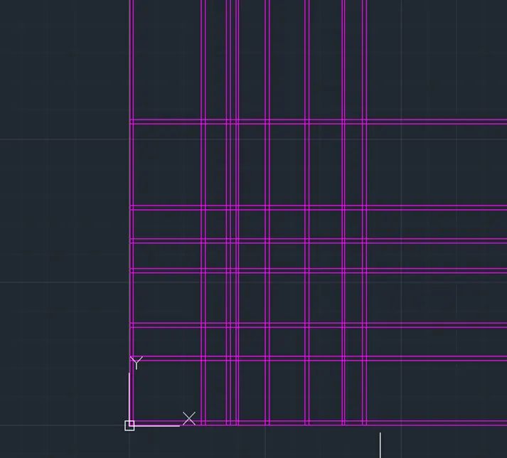
TRIM : Cut off all Unwanted Lines and keep the wall lines as per the plan and Save the Drawing.
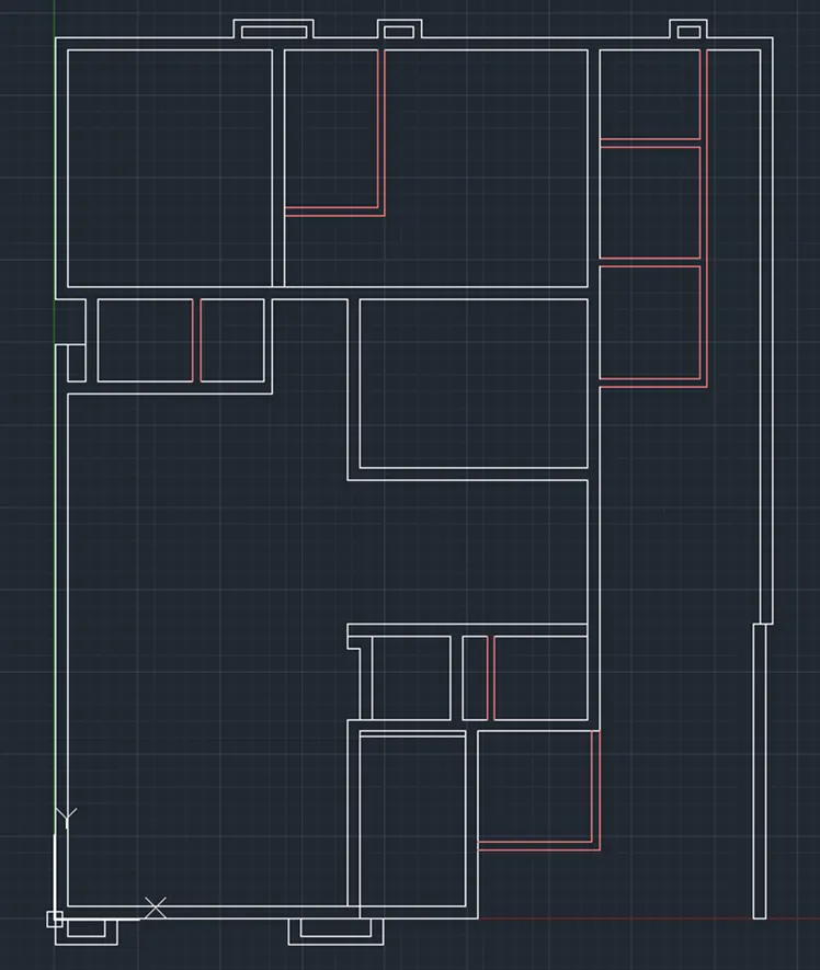
DOORS AND WINDOWS
LAYER: OPENINGS
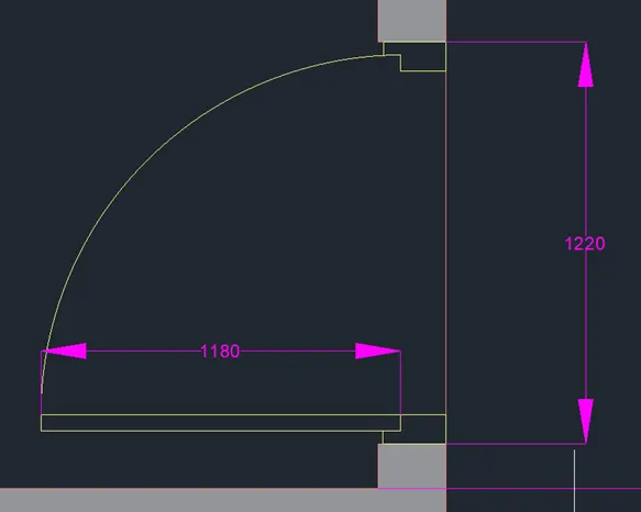
SIZES: DOORS D1- 1220 D2-1050, D3-950, D4 850, D5-830
WINDOWS W1-2430, W2-3030, W3-930, W9-730, W10 -1730
VENTILATORS V1-730, V2-630
Create Frame by 35 mm in Positive X Direction, 130 in Negative Y direction, 15 in Negative X Direction, 100 in Negative Y direction, 20 in Negative X direction and connect to wall,
Create a Rectangle of 45X45 & Place it at the Centre
Copy and Mirror the Object, place it at a Distance of 2430, and Connect the Line Between Rectangles
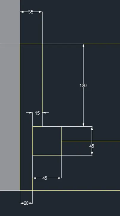
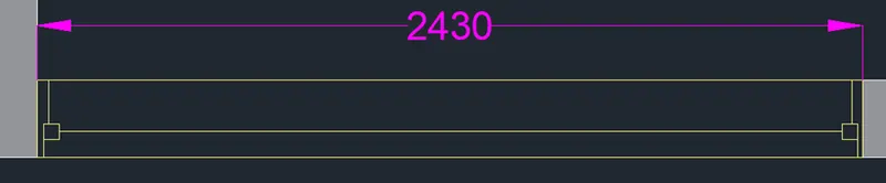
Similarly Create Remaining Windows, Ventilators, and Place it at desired Location as per the plan
Create the Frame as explained above
RECTANGLE: Create Rectangle of Width 25mm Length 1180 (Deducting 20mm at Both end of Frame width) to Create Door
CIRCLE: Select 3 Point Circle and Specify the Centre point as one end of Frame and End Point as another End of Frame Click ENTER
TRIM: Erase all Unwanted parts of the Circle
STAIRCASE :
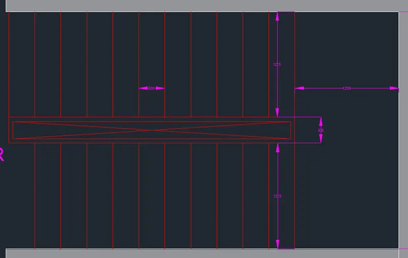
LAYER : STAIRCASE
OFFSET : Create The offset of 1200 from wall end and then Create 11 Offset of 300mm
RECTANGLE : Create a Rectangle of 3300 x 300 place it at Center
OFFSET : Create a Offset of 50
LAYER: Dimensions
DIMLENIAR: Select and Place the Desired Dimensions, Represent all the Dimensions
DIMSTY: Set Arrow size 100, Text Height 250, Precision to 0
DIMCONTINUE: Create Remaining Dimensions
MTEXT: Create a Text Box and Enter the sample text, Copy and Paste multiple in Desired Position and desired angle with Desired Size
EDIT TEXT (ED): Edit the MTEXT Created and Pasted and Type the actual name, size, rotation angle
HATCH:
LAYER: HATCH
Select the Solid Hatch with Colour 147,149,152 to Represent the WALL
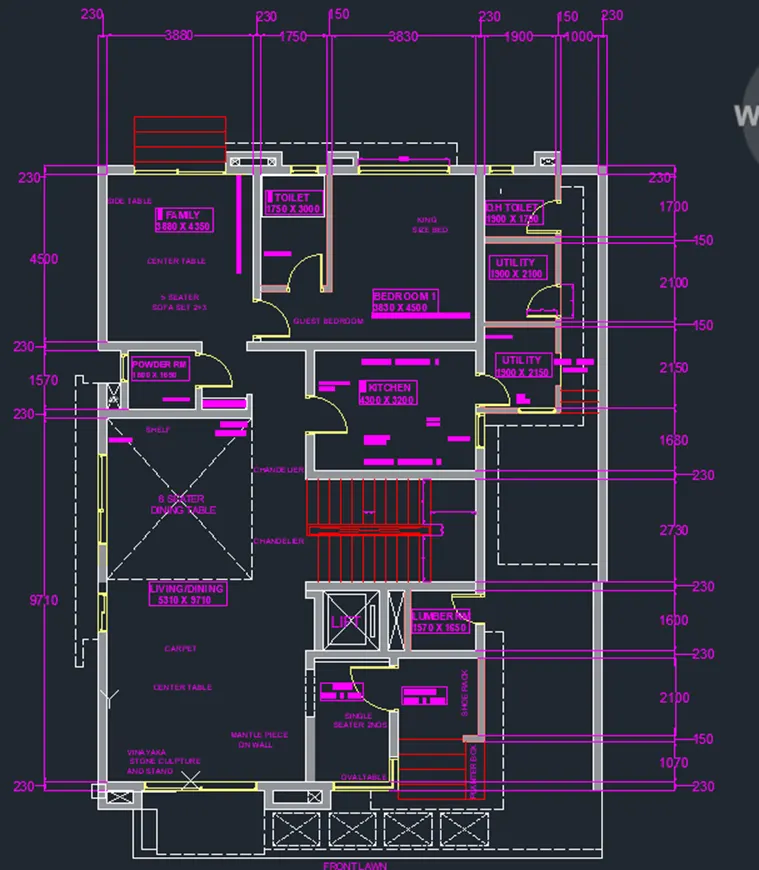
FURNITURES
LAYER :FURNITURES
DESIGN CENTER: TYPE DESIGN CENTER or Go to Insert tab, Insert Blocks, Insert Block From Libraries
Select the Desired Utility and Place it at the Right Location
LINE : select ISO02W100 to Create Dashed Line as per the Plan
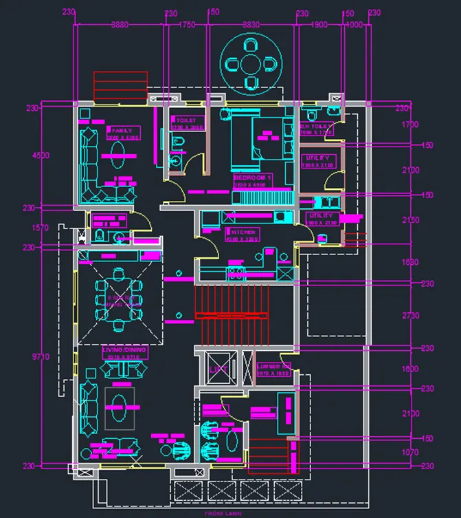
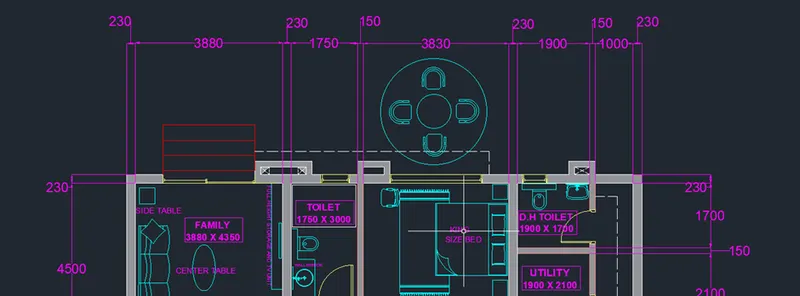
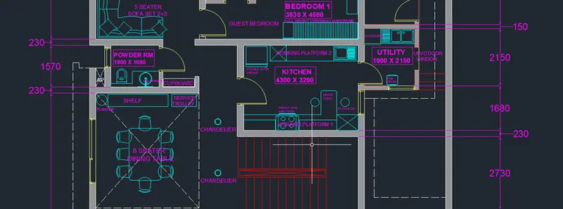
RESULT:
KITCHEN
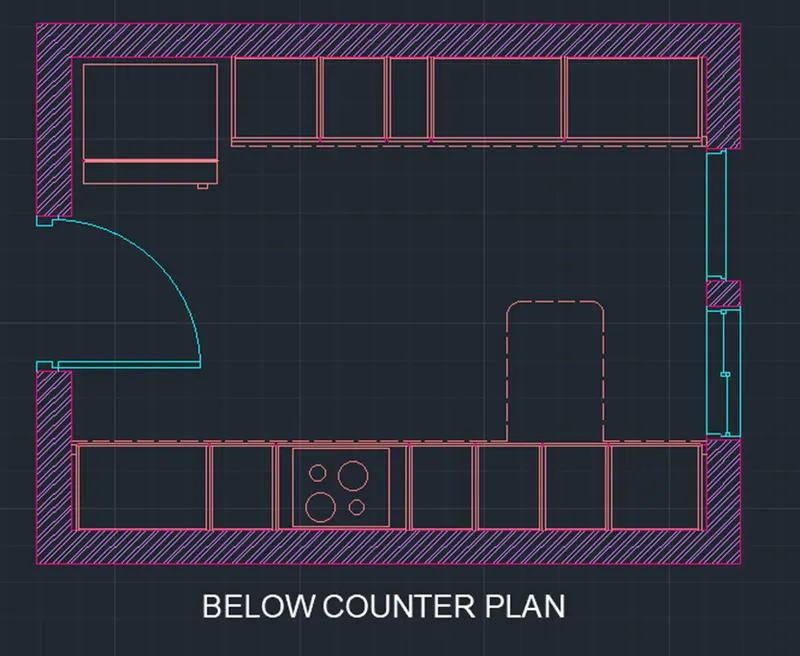
BELOW COUNTER PLAN
SETUP: Open AutoCAD select Advanced Setup , Use a WIZARD then select Unit of Measurement as Decimal, Precision 0.0,Insertion Scale as Millimetres.
LIMITS: specify 0,0 Enter Specify 5000,5000
LAYER: Create LAYERS and Specify Respective Colour and Properties
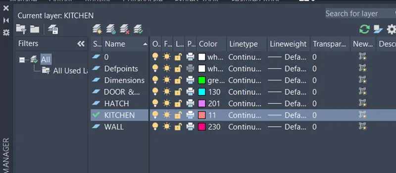
LAYER: KITCHEN
RECTANGLE: Create Rectangle of size 4300 x3200
OFFSET: Specify offset of 230, Click on the outside to offset
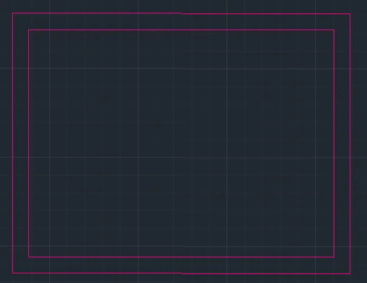
EXPLODE : Select the Interior Rectangle and Explode it
LINE: Specify the start point and Draw a line joining the inner edges of the kitchen wall
OFFSET : Line type -ISODASH ,Create an OFFSET at a Distance of 600 from baseline
RECTANGLE : Specify the First point as the left Corner below the osset line, Create 35x65
COPY : Copy the paste it in opposite end
OFFSET: OFFSET the lines at a distance of 630,450,450,450, 900,450,900 as Centerline, Specify offseof 20 mm and Create offset on both sides of Centerline
OFFSET: now create an offset of 10mm from baseline at each and every interior Rectangle
Create same plan on opposite side of wall
LINE: Specify the start point and Draw a line joining the inner edges of the kitchen wall
OFFSET : Line type -ISODASH ,Create an OFFSET at a Distance of 600 from baseline
RECTANGLE : Specify the First point as the left Corner below the osset line, Create 35x65
COPY : Copy the paste it in opposite end
OFFSET: OFFSET the lines at a distance of 930,900,300,450, 580 as Centerline, Specify offseof 20 mm and Create offset on both sides of Centerline
OFFSET: now create an offset of 10mm from baseline at each and every interior Rectangle
DOOR
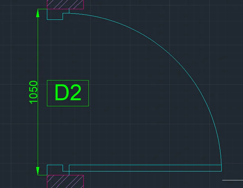
LINE: Create Frame by 35 mm in Positive X Direction, 130 in Negative Y direction, 15 in Negative X Direction, 100 in Negative Y direction, 20 in Negative X direction and connect to wall,
RECTANGLE: Create Rectangle of Width 25mm Length 1010 (Deducting 20mm at Both end of Frame width) to Create Door
CIRCLE: Select 3 Point Circle and Specify the Centre point as one end of Frame and End Point as another End of Frame Click ENTER
TRIM: Erase all Unwanted parts of the Circle
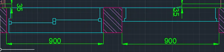
WINDOW
LINE: Create Frame by 35 mm in Positive X Direction, 130 in Negative Y direction, 15 in Negative X Direction, 100 in Negative Y direction, 20 in Negative X direction and connect to wall,
Create a Rectangle of 45X45 & Place it at the Centre
Copy and Mirror the Object, place it at a Distance of 900, and Connect the Line Between Rectangles
FURNITURES
LAYER :FURNITURES
DESIGN CENTER: TYPE DESIGN CENTER or Go to Insert tab, Insert Blocks, Insert Block From Libraries
Select the Desired Utility and Place it at the Right Location
LINE : select ISO02W100 to Create Dashed Line as per the Plan
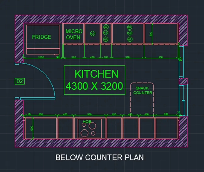
LAYER: Dimensions
DIMLENIAR: Select and Place the Desired Dimensions, Represent all the Dimensions
DIMSTY: Set Arrow size 100, Text Height 250, Precision to 0
DIMCONTINUE: Create Remaining Dimensions
MTEXT: Create a Text Box and Enter the sample text, Copy and Paste multiple in Desired Position and desired angle with Desired Size
EDIT TEXT (ED): Edit the MTEXT Created and Pasted and Type the actual name, size, rotation angle
HATCH:
LAYER: HATCH
Select the ANSI32 to Represent the BRICK WALL
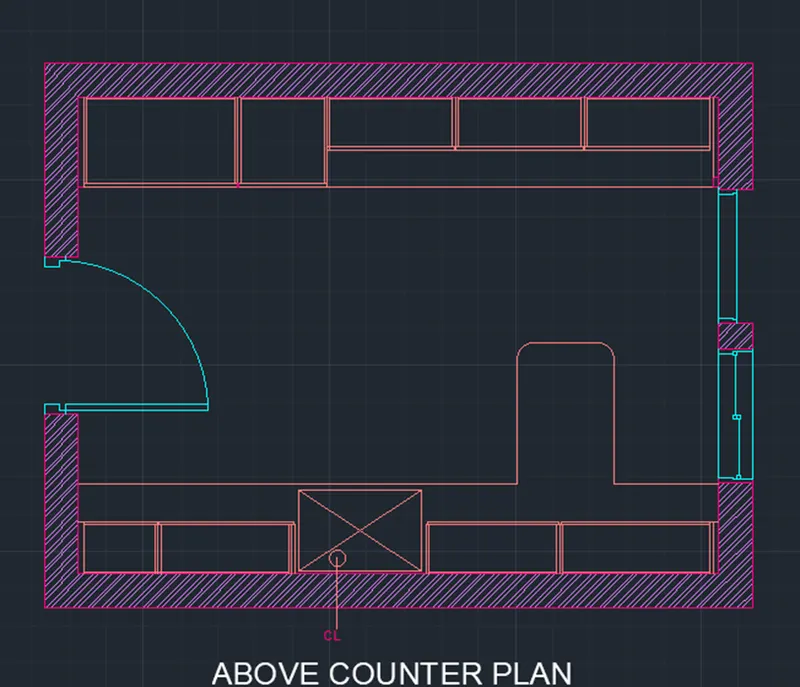
ABOVE COUNTER PLAN :
LAYER: KITCHEN
RECTANGLE: Create Rectangle of size 4300 x3200
OFFSET: Specify offset of 230, Click on the outside to offset
LINE: Specify the start point and draw a line joining the inner edges of the kitchen wall
OFFSET: Line type -ISODASH, Create an OFFSET at a Distance of 600 from baseline
EXPLODE: Select the Interior Rectangle and Explode it
OFFSET: offset 10mm from Both opposite ends from wall interior side
350mm from Baseline at Both Ends
RECTANGLE: Specify the First point as the left Corner below the ofsset line, Create 35x65
COPY: Copy the paste it in opposite end
OFFSET: OFFSET the lines at a distance of 20,1010,900, 900 ,900, 500,35 as Centreline,
Specify offset of 20 mm and Create offset on both sides of Centreline
LINE: Specify the start point and Draw a line joining the inner edges of the kitchen wall
OFFSET: Create an OFFSET at a Distance of 350 and 600 and from baseline on opposite side
RECTANGLE : Specify the First point as the left Corner below the offset line, Create 35x65
COPY : Copy the paste it in opposite end
OFFSET: OFFSET the lines at a distance of 865,865,865(for 350 width ),600, 1035,35 as Centreline, Specify offset of 20 mm and Create offset on both sides of Centreline
Layer : Furniture
RECTANGLE : Specify first point at a distance of 1500 from Left inner Wall and Specify 800,500
LINE: Create the Diagonal Lines For Previously created Rectangle
TRIM : cut off all the unwanted lines intersecting , and lines extending beyond 350mm at right side of kitchen.
LAYER: Dimensions
DIMLENIAR: Select and Place the Desired Dimensions, Represent all the Dimensions
DIMSTY: Set Arrow size 100, Text Height 250, Precision to 0
DIMCONTINUE: Create Remaining Dimensions
MTEXT: Create a Text Box and Enter the sample text, Copy and Paste multiple in Desired Position and desired angle with Desired Size
EDIT TEXT (ED): Edit the MTEXT Created and Pasted and Type the actual name, size, rotation angle
HATCH:
LAYER: HATCH
Select the ANSI32 to Represent the BRICK WALL
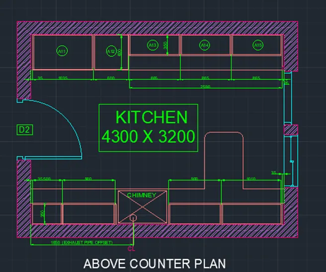
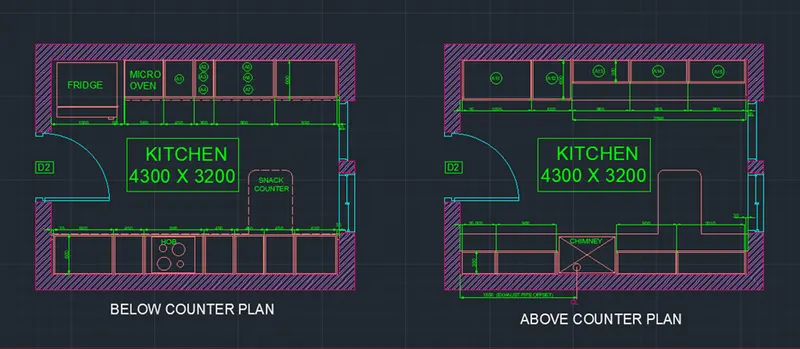
RESULT:
RAFT :
SETUP: Open AutoCAD select Advanced Setup , Use a WIZARD then select Unit of Measurement as Archetectural, Precision 0’-0 1/2” ,Insertion Scale as INCHES.
LIMITS, Specify 0,0 Enter Specify 5000,5000
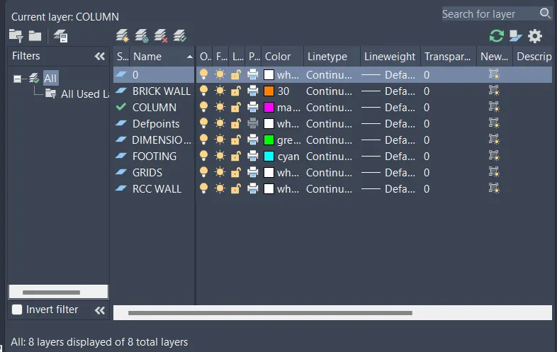
LAYER: Create LAYERS and Specify Respective Colour and Properties
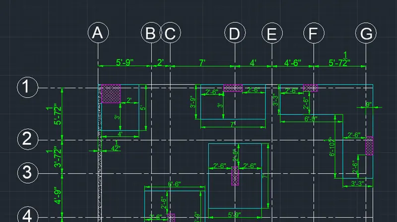
LAYER: GRIDS
XLINE: Create a Horizontal and Vertical Xlines Intersecting at a Point
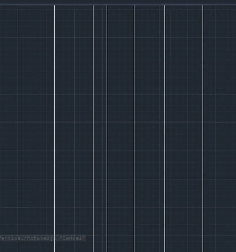
LINETYPE: ISO DASH
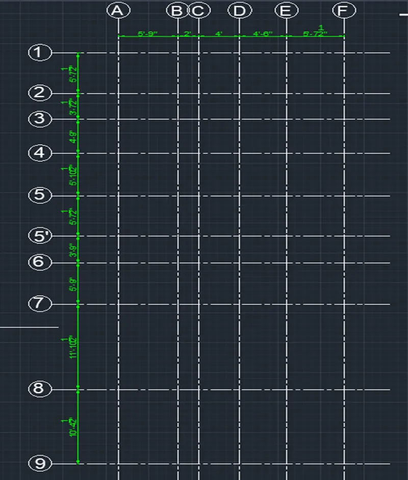
OFFSET : Create the Gridlines in Positive X axis by Specifying offset Distance of 69,24,84,48,54,67.5
Create the Gridlines in Positive Y axis by Specifying offset Distance of 124.5, 142.5,, 69,45,67.5,70.5,57,43.5,67.5
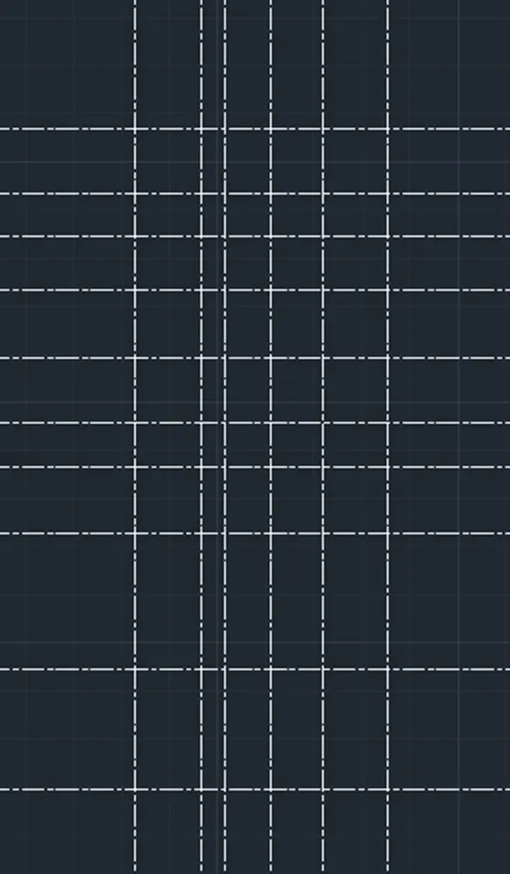
DIMLENIAR : Check the Distance Between the Grid Lines
QLEADER : Select lines and Specify the Grid Name for all the Grid lines
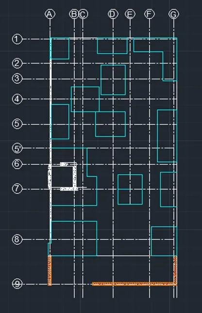
OFFSET : to create RC wall specify the offset distance 4.5 and and select grid A Click positive x direction, Select Grid 1 in towards positive Y direction (Let us call it as Grid 1’)
Specify 9” and select F grid Click positive x direction
LINE: Specify first point of line at a Distance of 120 inches from 9 grid towards F grid create the line to touch F grid to make 9” wall
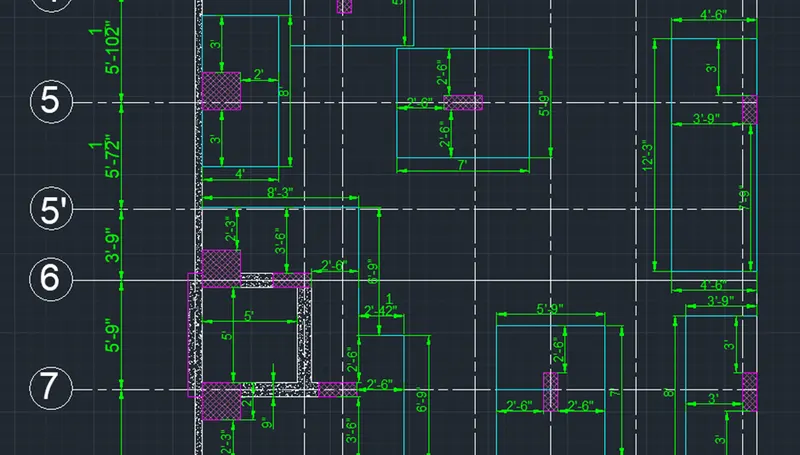
FOOTINGS
LAYER : FOOTINGS
RECTANGLE :
- Specify First point as 1A, Specify Dimension as 48,-60
- Specify First point at a distance of 39.5 from Grid C at 1’ and Specify 49, -45
LINE: Specify First point as 10.5 from Grid E at 1’, and 39 in -Y, 81 in +X, 82.5 in -Y, 39 in +X, 121.5 in +Y, and Close the Line
RECTANGLE:
- Specify First point at a distance of 49.5 from Grid C & 12 from Grid 4 and Specify 69,84
- Specify First point at a distance of 55.5 from Grid 5 & 60 from Grid A and Specify 78,69
- Specify First point at a distance of 4.5 from Grid A & 40.5 -Y from Grid 5 and Specify 52.5,96
- Specify First point at Grid A & 40.5 -Y from Grid 5 and Specify 52.5,96
- Specify First point at a distance of 127.5 from Grid A & 34.5 -Y from Grid 5 and Specify 84,69
- Specify First point at a distance of 22.5 from Grid F & 6 in +Y from Grid 6 and Specify 54,123
LINE: Specify First point as 1.5 in +X from Grid A at 5’, and 103.5 in +X, 81 in -Y, 28.5 in +X, 81 in -Y, 132 5 in -X, and Close the Line
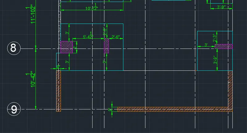
RECTANGLE:
- Specify First point at a distance of 13.5 in +X from Grid D & 43.5 in -Y from Grid 7 and Specify 69,84
- Specify First point at a distance of 31.5 in +X from Grid F & 49.5 in -Y from Grid 7 and Specify 45,96
LINE: Specify First point as 4.5 in +X from Grid A on Grid 8, and 51 in +Y, 127.5 in +X , 96 in -Y, 136.5 in -Y, 36 in + X, and Close the Line
RECTANGLE:
- Specify First point at a distance of 4.5 in +X from Grid F & 45 in -Y from Grid 8 and Specify 72,81
Now all 13 Footings are Completed
Columns
LAYER : Columns
RECTANGLE : Specify First Point and Create Rectangle of size 24x24, 9x18, 9x24, 9x30, 9x36
HATCH : Select ANSI37, Scale 1, Hatch specified Pattern inside the Columns
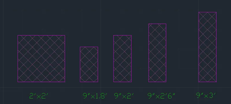
COPY: Select 2’x2’ Column, Specify the Base point as the Top right Corner of the Column
Place it at a distance of 4.5 in +X, 4.5 in +Y at Grid 1A
Keep Ortho ON
Select and Copy the Previously placed Rectangle and place it at a Distance of 19.5 from Grid 5 and another in 19.5 from Grid 6, Another in 4.5 from Grid 7
Select 9”x1.8’ Specify Base Point as Top Right Corner and Place it at a Distance of 30 in Both Direction for the footing at 4-C and at a offset of 36 from Grid 5 at Grid G
ROTATE : Select 9”x1.8’Rectangle Specify the Rotation angle as 90
Copy the Rotated Column and Specify the Base point as Top Right Corner Place it at a distance of 40.5 from Grid E, at Grid 1
COPY: Select 9”x2’ Specify Base Point as Top Right Corner and Place it at a Distance of 30 on both side at the Footing at D3
Place another at a Distance of 67.5 +X from Grid F and 63 -Y from Grid 1
Place Another at a Distance of 30 on both side at the Footing at E7 and 36 on both ends of a Footing at 7G
ROTATE : Select 9”x2 ’Rectangle Specify the Rotation angle as 90
Copy the Rotated Column and Specify the Base point as Top Right Corner Place it at a distance of 69.5 from Grid C , 4.5 from Grid 1
Place another at a distance of 30 on both ends of a Footing at D5
Place another at a distance of 49.5 +X from Grid A and 40.5 from Grid 5’
Place another at a distance of 9 +X from Grid B and 4.5 from Grid 7
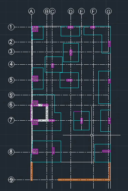
Select 9”x2’’6” Specify Base Point as Top Right Corner and Place it at a Distance of 24 in +X from Grid B, and 21 in +Y Direction at Grid 8C
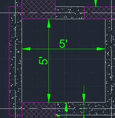
RECTANGLE : Specify the First point as Top right corner of the Column at 7A and Specify the Dimensions as 60,60
OFFSET : Specify offset as 9”and Click on Outside the Rectangle
TRIM : cut off the unwanted lines
HATCH : Select AR-CONC and Hatch the Boundary
LAYER: Dimensions
DIMLENIAR: Select and Place the Desired Dimensions, Represent all the Dimensions
DIMSTY: Set Arrow size 6” Text Height 8”, Precision to 0
DIMCONTINUE: Create Remaining Dimensions
MTEXT: Create a Text Box and Enter the RAFT FOUNDATION PLAN
EDIT TEXT (ED): Edit the MTEXT Created Size as 12”, Font ARIAL, Bold
Save the Drawing
RESULT :