Creating a Wardrobe detailed drawing, Floor Plan, Kitchen Layout and Column Detail using AutoCad
16/06/21
Answer
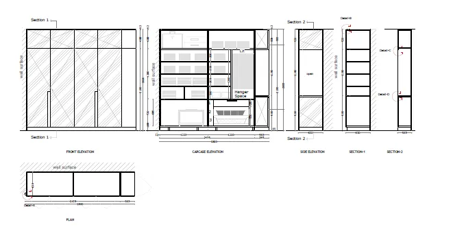
Q1. Draw the elevation and details of a wardrobe.
Aim
To draw the elevation an details of a wardrobe using autocad.
Procedure
STEP-1 opening to the AutoCAD software and entering the workspace.
STEP-2 Setting limits >specify lower-left corner:0,0
STEP-3 specify upper-left corner:100,100
STEP-4 Set>units>Demical>intersectional scale>mm
STEP-5 Limmax>100,100
Front Elevation
STEP-6 to create rec command>2800,2600 as a outer frame.
STEP-7 offset command>12 for the top
STEP-8 offset command>488 to the inner frame
STEP-9 offset command>2100 till last
STEP-10 offset command>100,720,1280
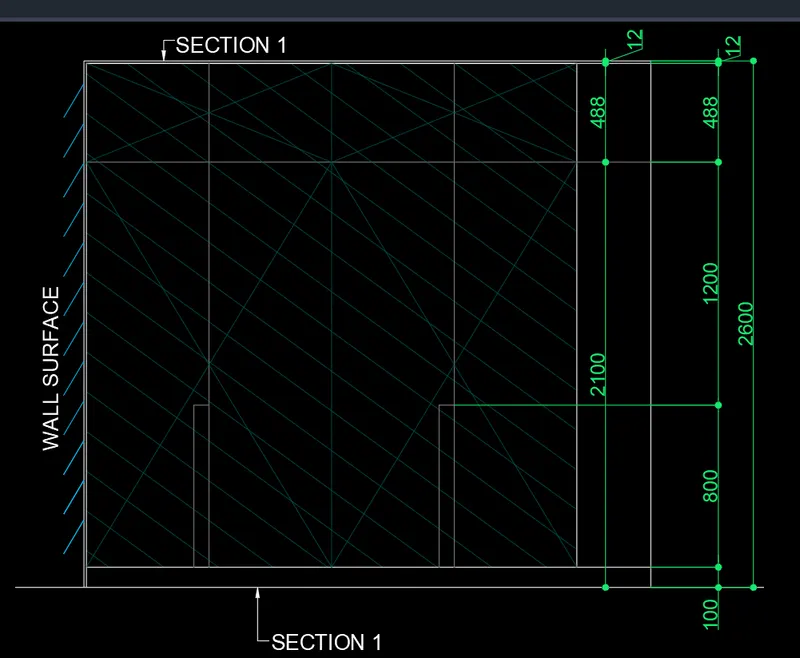
Plan
STEP-11 offset command>630 top layer
STEP-12 Detail-A offset command>2435
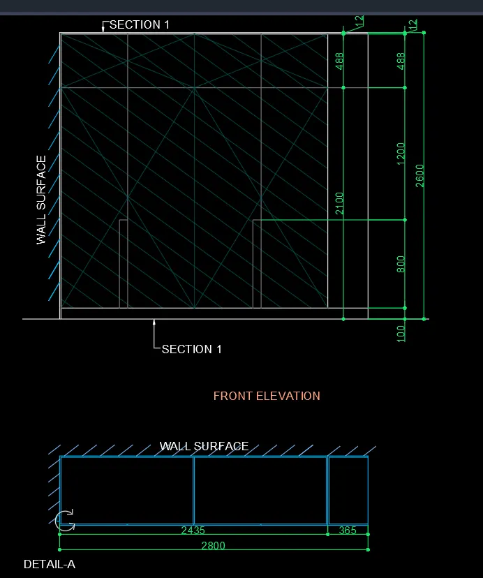
Carcase Elevation
STEP-13 to create rec command>2800,2600 as a outer frame.
STEP-14 vertical axis,offset command>12,1223,1200,365
STEP-15 offset command>2435,365 frame to darw
STEP-16 compartment size 1260.
STEP-17offset command>300,300,300
STEP-18 trim command> used to trim to clear all unwanted lines.
STEP-19 offset command> 680 to open the big space.
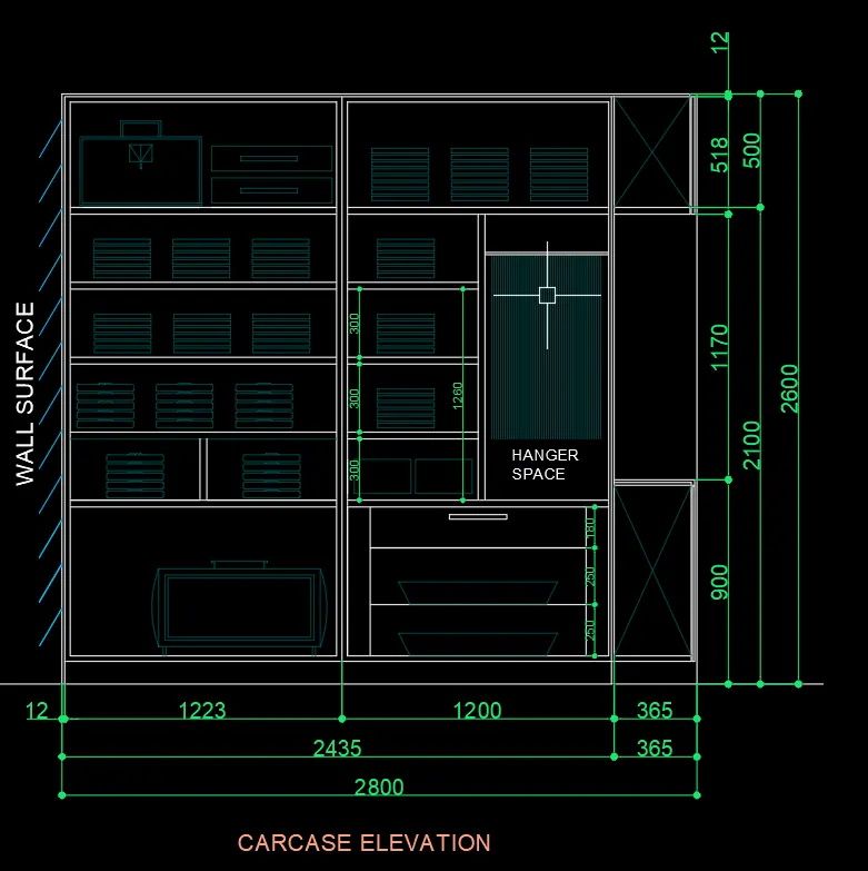
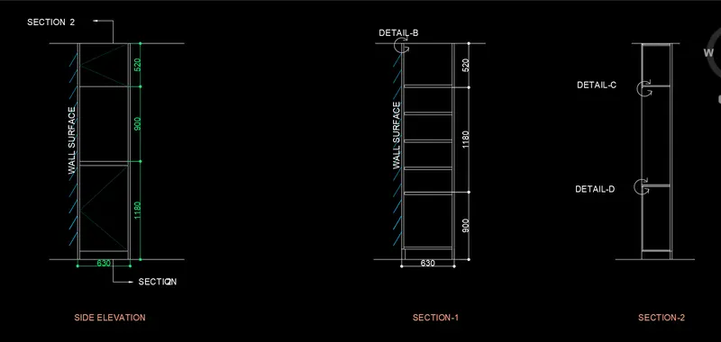
Side Elevaion
STEP-20 offset command>900,and make the offset>30 of frame
STEP-21 offset command>1180,frame 630
STEP-22 offset command>520,frame 630
STEP-23 hatch command>pick select to hatch
STEP-24 trim command> unwanted line to be removed
Section-1
STEP-25 Offset command>630,900
STEP-26 Offset command>1180 to open frame
STEP-27 Offset command> 520 to frame
Section-2
STEP-28 Offset command>2600,365
STEP-29 Offset command>900
STEP-30 Offset command>520 to frame
STEP-31 trim command>unwanted line to be removed
STEP-32 close the entire object
STEP-33 and save the file for feature use.
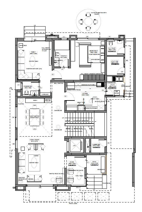
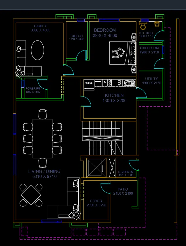
Q2. Draw the floor plan. Use the proper drafting tools to sketch the plan.
Aim
To Draw the floor plan. Use the proper drafting tools to sketch the plan using autocad.
Procedure
STEP-1 opening to the AutoCAD software and entering the workspace.
STEP-2 Setting limits >specify lower-left corner:0,0
STEP-3 specify upper-left corner:100,100
STEP-4 Set>units>Demical>intersectional scale>mm
STEP-5 Limmax>100,100
STEP-6 use the construction line to draw the boundary
STEP-7 External wall -230 and interior wall -150 to draw the boundary
family room(3880 x 4350)
STEP-8 offset command> to make the boundary on four sides
STEP-9 trim command> help to trim the all unwanted line in the area
STEP-10 make the sofa in the corner of the room for the 5 seater
STEP-11 centre table in the the family room
toilet-01(1750 X 3000)
STEP- 12 offset command> to make the boundary on four sides
STEP-13 trim command> help to trim the all unwanted line in the area
STEP-14 make the wall mirror, door, and bathroom closet in to required area
STEP-15 window to the other end of the room
bedroom-01
STEP-16 offset command> to make the boundary on four sides
STEP-17 trim command> help to trim the all unwanted line in the area
STEP-18 make the bed in the right location and window in side of it
D.H toilet(1900 X 1700)
STEP-19 offset command> to make the boundary on four sides
STEP-20 trim command> help to trim the all unwanted line in the area
STEP-21attched the door to the room and bathroom closet to the area
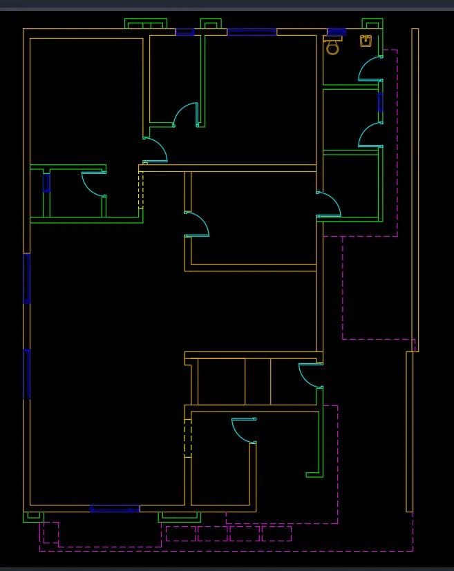
Utility RM
STEP-22 offset command> to make the boundary on four sides
STEP-23 trim command> help to trim the all unwanted line in the area
STEP-24 attched the door to the room and bathroom closet to the area
Utility(1900 x 2150)
STEP-25 offset command> to make the boundary on four sides
STEP-26 trim command> help to trim the all unwanted line in the area
STEP-27 attched the door to the room and bathroom closet to the area
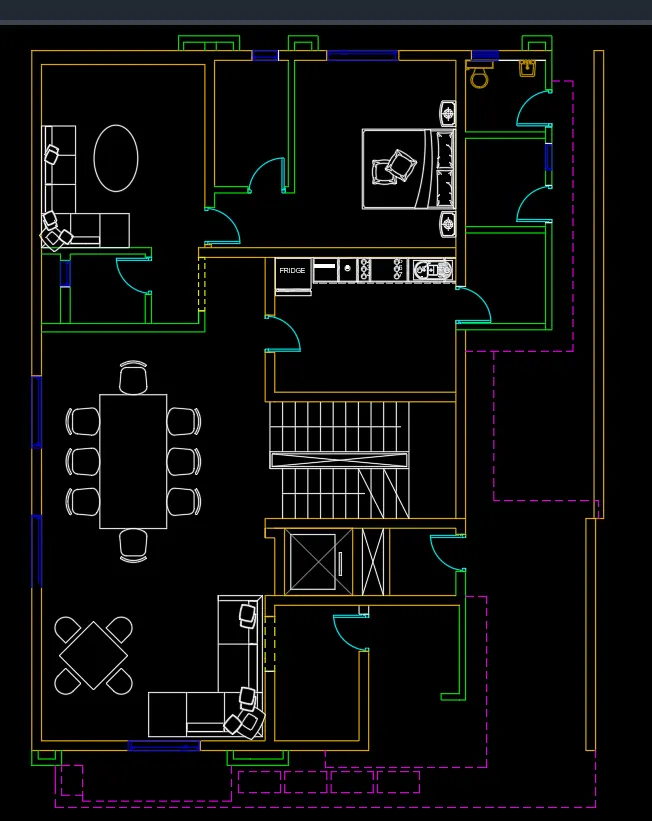
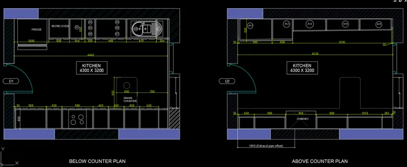
kitchen(4300 X 3200)
STEP-28 offset command> to make the boundary on four sides
STEP-29 trim command> help to trim the all unwanted line in the area
STEP-30 attched the door,smminey,snake table and working platform
STEP- 31 stair to set it done using the offset command and div command to get it done
STEP- 32 LAyers Management command> to help as to decide to layers to the define colour
STEP- 33 dimension command> it help as to define the room in the define sizes
STEP- 34 dotted line for the hidden portions
STEP-35 close the entire object
STEP-36 and save the file for feature use.
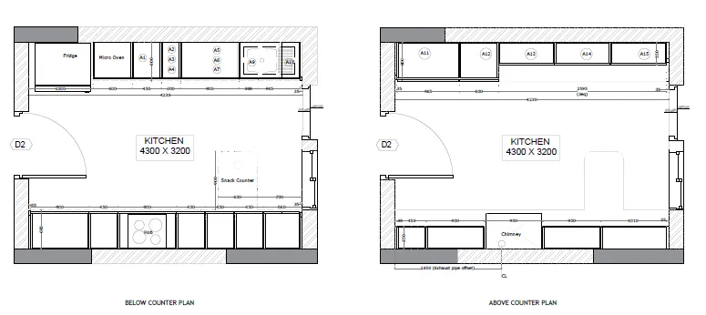
Q3. Create the Kitchen Layout.
Aim
To draw Create the Kitchen Layout using autocad.
Procedure
STEP-1 opening to the AutoCAD software and entering the workspace.
STEP-2 Setting limits >specify lower-left corner:0,0
STEP-3 specify upper-left corner:100,100
STEP-4 Set>units>Demical>intersectional scale>mm
STEP-5 Limmax>100,100
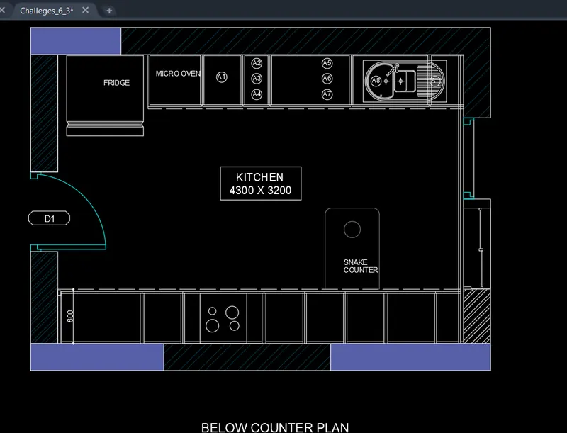
Below counter plan
STEP-6 offset command> to make the boundary on four sides
STEP-7 trim command> help to trim the all unwanted line in the area
STEP-8 Offset command>100,600,450,300,900,300,945,35
STEP-9 all these measurement are to divide the parts
STEP-10 total area of 4230 are the right side section
STEP-11 total area of 4230 are the leftside section also
STEP-12 but the different in the segments
STEP-13 offset command> 35,900,450,900,450,450,450,560,35
STEP-14 trim command> to remove the all unwanted line in the boundarys
STEP-15 door, window, french door are provided in the side
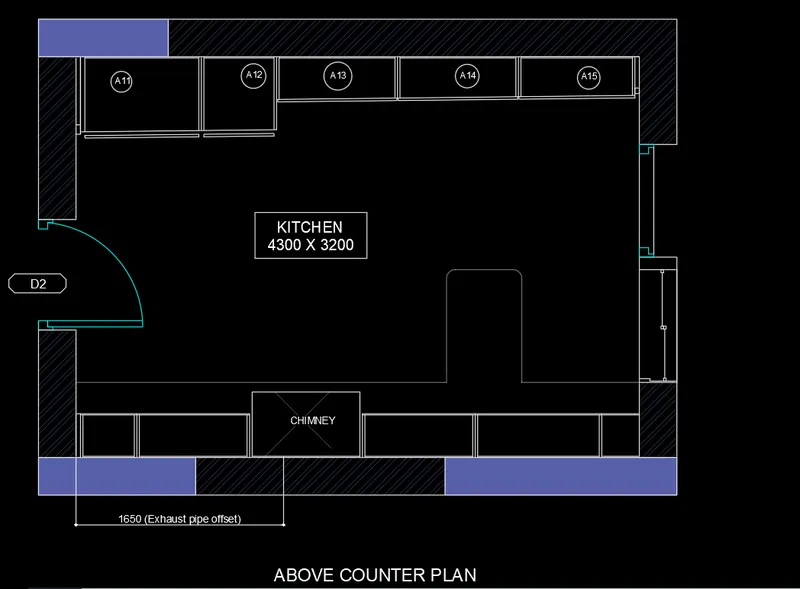
Above counter paln
STEP-16 same as the below, first we fixed the boundary 4230 of vertical axis.
STEP-17 offset command> of 350 to all compartments.
STEP-18 all required things are allocated in the area.
STEP-19 door and widow to locate in the right place.
STEP-20 chimney are provided in the process and above that 1650 of exhaust pipes offset is required
dimension
STEP-21 mtext command> used in the dimension areas.
STEP-22 DLI command> to put the dimension
STEP-23 Hatch command>pick the footing to hatch
STEP-24close the entire object
STEP-25and save the file for feature use.
Q4. Sketch the column details.
Aim
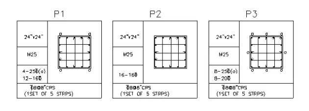
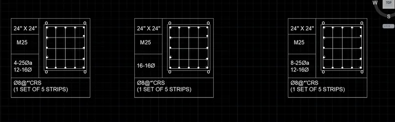
To Create a column schedule using AutoCAD
Procedure
Step-1 opening to the AutoCAD software and entering the workspace.
Step-2 Setting limits >specify lower-left corner:0,0
Step-3 specify upper-left corner:100,100
Step-4 Set>units>Architectural>intersectional scale>inches
Step-5 Limmax>100,100
Step-6 rectangle command> to create a rectangle of required dimension
Step-7 line command> to draw the line as the reference.
Step-8 offset command> offset the x-axis in the required dimension and repeat the same in the Y-axis
Step-9 trim command> trim all unnecessary lines remaining.
Step-10 multitext command>make the text in the required size and define location.
Step-11 rotate command>rotate the text towards the Y-axis
Step-12 copy command>copy the text to all required areas.
Step-13 rectangle command> to create the rectangle and place the circle on all side of the rectangle
Step-14 line command> the line help to join the circles presents in the column rebars
STEP-15 close the entire object
STEP-16 and save the file for feature use.
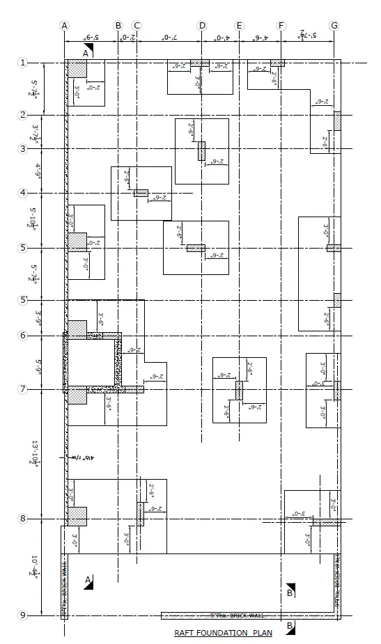
Q5. Draw the Raft Layout as shown in the Figure.
Aim
To Draw the Raft Layout using autocad
Procedure
STEP-1 opening to the AutoCAD software and entering the workspace.
STEP-2 Setting limits >specify lower-left corner:0,0
STEP-3 specify upper-left corner:100,100
STEP-4 Set>units>Demical>intersectional scale>mm
STEP-5 Limmax>100,100
boundary lines
STEP-6 offset command> to make the boundary on four sides
STEP-7 trim command> help to trim the all unwanted line in the area
STEP-8 Offset command>measurements required as boundarys.
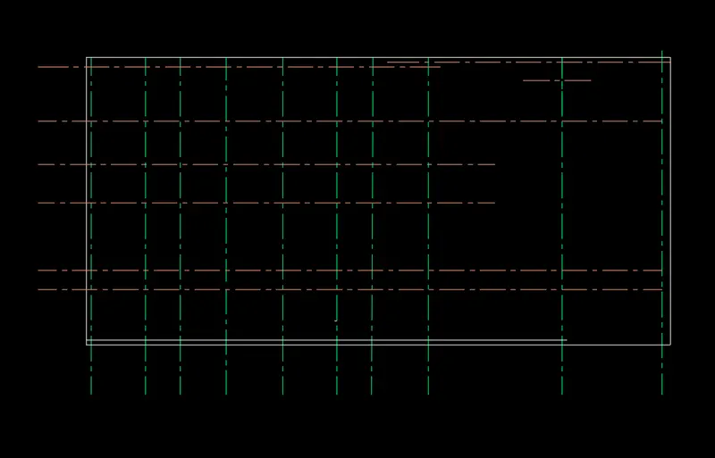
centerline marking
STEP-9 make the boundary with the XL,XV
STEP-10 start with the offset command in the dimension in the X-axis
STEP-11 offset command> all measurement are noted in the plan given.in X-axis
STEP-12 start with the offset command in the dimension in the Y-axis
STEP-13 offset command>all measurement are noted in the plan given.in Y-axis footing fixing
STEP-14 all the measurement in the 2',3',2.6' so put in the right ways.
STEP-15 circle command> all put in the x-axis and Y-axis for the purpose of measurement.
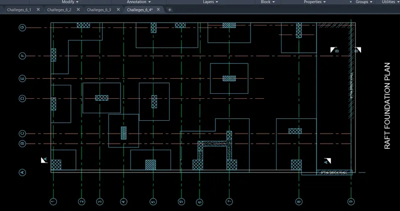
dimension
STEP-16 mtext command> used in the dimension areas.
STEP-17 DLI command> to put the dimension
STEP-18 Hatch command>pick the footing to hatch
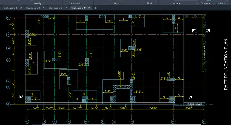
STEP-21close the entire object
STEP-22 and save the file for feature use.