Creating a Wardrobe detailed drawing, Floor Plan, Kitchen Layout and Column Detail using AutoCad
1.
Aim
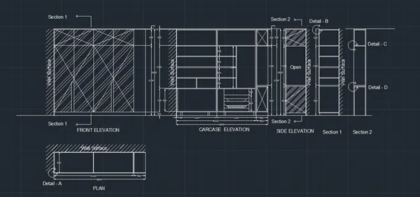
To draw a elevation and section of a wardrobe as shown in the figure. Also to provide dimensions and text in appropriate places.
Procedure
- Go to AutoCAD and use unit commend to fix the units.
- Use Decimal and precision as 0.0 in units.
- Then start sketching by using line commend.
- Sketch the plan as shown in the figure.
- Then draw front elevation, side elevation and section views as shown in the figure.
- After drawing use annotate tab to provide dimensions.
- Type dim linear and click start point and then end point and place the dimension.
- Then dim continue and continue the dimension till necessary.
- Provide dimension where ever necessary by using same points.
- Provide text comment and type the required text.
- Then place the text at required place.
- Thus the wardrobe and its section has been created and dimensions are provided.
Output
Result
Thus the elevation and section of a wardrobe has been drawn as shown in the figure. Also dimensions and text are provided at appropriate places.
2.
Aim
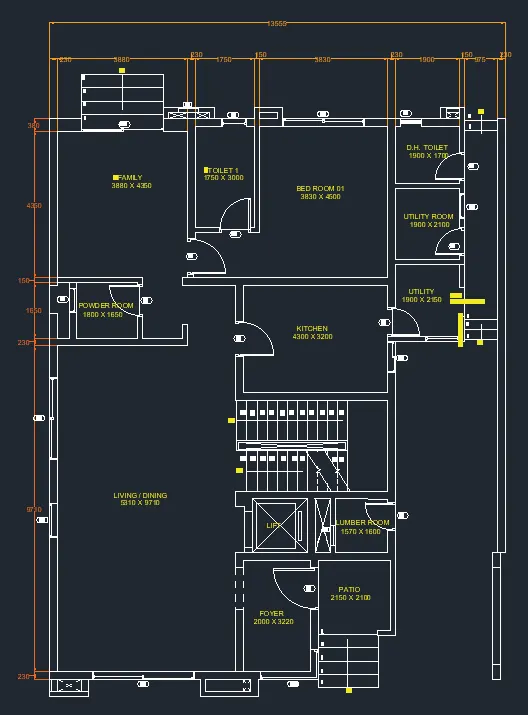
To Draw the floor plan as shown in the Figure.
- Draw external and internal walls
- Provide doors and windows
- Provide dimensions and text
Procedure
- Go to AutoCAD and use unit commend to fix the units.
- Use Decimal and precision as 0.0 in units.
- Then start sketching by using line commend.
- Sketch the plan as shown in the figure.
- Use thickness of wall as 230mm for external and 150 mm for internal.
- Then use offset commend to offset the drawn line at required width.
- Then use trim commend to trim the lines which are extending beyond the plan. Where ever line is not required.
- Then provide doors and windows as required.
- Provide stair case of threat 300mm and riser 150mm
- Then provide dimensions for the plan at the outer surface by using Dim linear commend.
- Then use dim continue commend and continue the dimension up to the last point.
- After providing dimension use m text commend to provide text.
- Provide appropriate height of text and place it at appropriate places.
Output
Result
Thus the Plan given in the figure has been drawn and all the dimensions and text has been provided wherever necessary.
3.
Aim
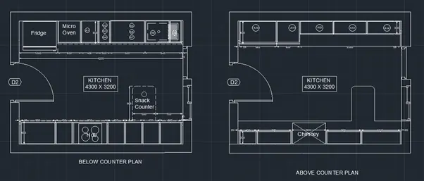
To create a kitchen layout as shown in the figure. And to provide the dimensions of the kitchen wherever necessary.
Procedure
- Go to AutoCAD and use unit commend to fix the units.
- Use Decimal and precision as 0.0 in units.
- Then start sketching by using line commend.
- Sketch the plan as shown in the figure.
- Use thickness of wall as 230mm for external and 150 mm for internal.
- Then use offset commend to offset the drawn line at required width.
- Then use trim commend to trim the lines which are extending beyond the plan. Where ever line is not required.
- Then use dim continue commend and continue the dimension up to the last point.
- After providing dimension use m text commend to provide text.
- Provide appropriate height of text and place it at appropriate places.
Output
Result
Thus the kitchen layout has been created as shown in the figure and all the dimensions are marked in the plan and text has been inserted at required places.
4.
Aim
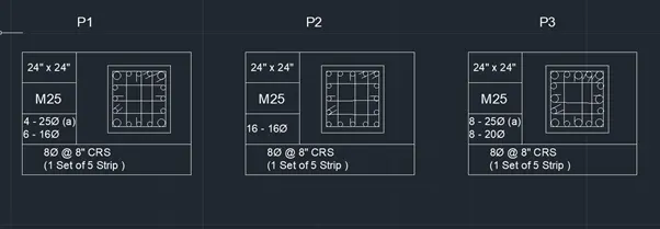
To draw the details of column as show in the figure and to give dimensions and text to the plan.
Procedure
- Go to AutoCAD and use unit commend to fix the units.
- Use Engineering and precision as 0’0” in units.
- Then start sketching by using line commend.
- Sketch the plan as shown in the figure.
- Use rectangle to draw a rectangle and line commend to draw a line.
- Then use offset to draw multiple lines at specific distance.
- Then use circle commend to draw a circle.
- And line commend to draw lines at required places.
- Then provide m text to write the text. Change the size for better appearance.
- Similarly create another two boxes with same procedure.
Output
Result
Thus the reinforcement details have been dawn.
5.
Aim
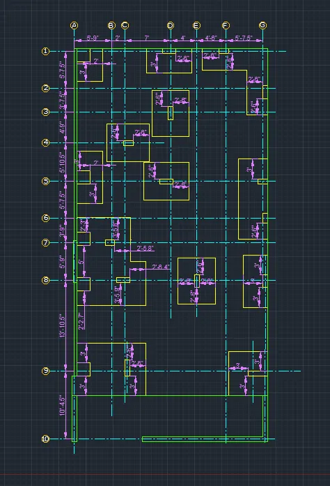
To draw a raft foundation layout as shown in the figure and to provide dimensions as required.
Assume the size of the columns.
Procedure
- Go to AutoCAD and use unit commend to fix the units.
- Use Engineering and precision as 0’0” in units.
- Then start sketching by using line commend.
- Sketch the plan as shown in the figure.
- Use rectangle to draw a rectangle and line commend to draw a line.
- Create layouts for easy understanding.
- Give different colours to different layout. Also provide different line type as well for different layouts.
- Then use dim continue commend and continue the dimension up to the last point.
- After providing dimension use m text commend to provide text.
- Provide appropriate height of text and place it at appropriate places.
Output
Result
Thus the Raft foundation layout has been created and all the dimensions are mentioned in the drawing.