Creating a Wardrobe detailed drawing, Floor Plan, Kitchen Layout and Column Detail using AutoCad
Q1
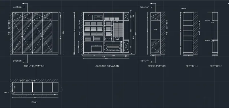
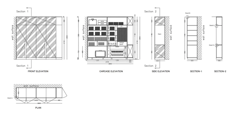
Draw the elevation and details of a wardrobe as shown in the Figure below. After sketching, you need to provide the dimensions and text with the use of layers. Use proper text styles and dimension methods to document it. Also, assume dimensions, wherever needed.
Note: All dimensions are in mm.
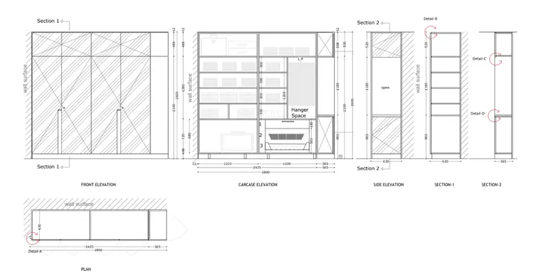
AIM
To draw the elevation and details of a wardrobe as shown in the figure, also provide the dimensions and text with the use of layers.
PROCEDURE
Open the AutoCAD Application and create a new AutoCAD file with imperial settings. Set the units in 'Decimal' and precision (0).
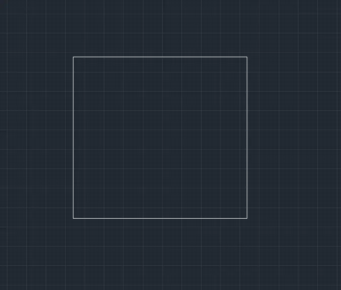
1. Type 'REC' in the command line and press enter to get rectangle
- Specify first corner point: Choose any point
- Specify other corner point or [Area/Dimensions/Rotation]: @2800,2600
- Select the rectangle and click explode on the panel.
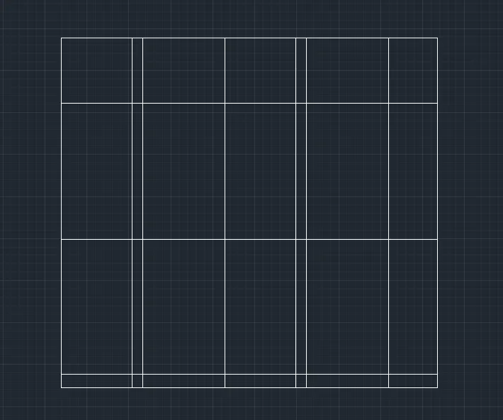
2. Type 'OFF' in the command line and press enter to get offset tool
- Specify offset distance: 608.75
- Select object to offset: Click the left line
- Specify point on side to offset: 4 times in the x direction
- Specify offset distance: 100
- Select object to offset: Click the bottom line
- Specify point on side to offset: y direction
- Specify offset distance: 12
- Select object to offset: Click the top line
- Specify point on side to offset: -y direction
- Specify offset distance: 488
- Select object to offset: Click the offset top line
- Specify point on side to offset: -y direction
- Specify offset distance: 1000
- Select object to offset: Click the second last bottom line
- Specify point on side to offset: y direction
- Specify offset distance: 80
- Select object to offset: Click the second line from left
- Specify point on side to offset: -x direction
- Specify offset distance: 80
- Select object to offset: Click the fourth line from left
- Specify point on side to offset: -x direction
3. Type 'TR' in the command line and press enter to get trim tool
- Trim all the unnecessary lines from the drawn lines
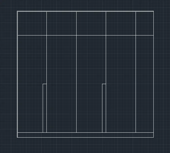
4. Type 'L' in the command line and press enter to get line tool
- Draw the line to mark the door opening direction
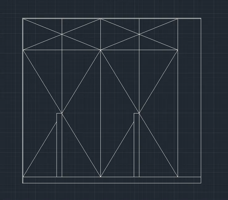
5. Type 'HATCH' in the command line and press enter to get hatch tool
- Draw a closed rectangle left of the wardrobe outside for hatching the wall surface
- Pick internal point: Click inside the new rectangle (ANSI31; Hatch Transparency: 42)
- Pick internal point: Select all the portions of wardrobe (ANSI34; Hatch Transparency: 42)
- Delete the rectangle drawn
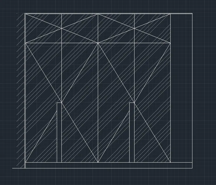
6. Type 'RAY' in command line and enter to get ray line
- Specify the start point
- Specify through point: -y direction
- Repeat the above steps to attain the desired design
- Specify the start point
- Specify through point: x direction
- Repeat the above steps to attain the desired design
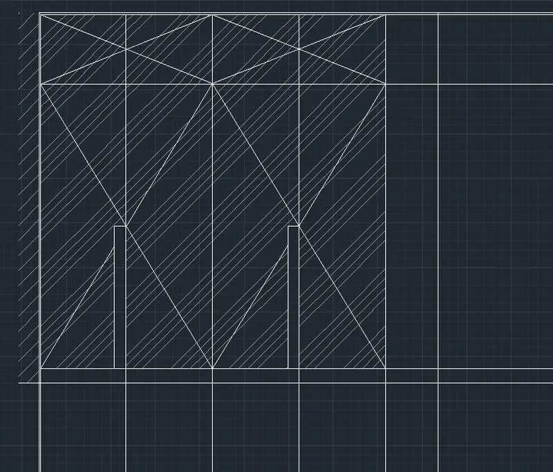
7. Type 'OFFSET' in command line and enter to get offset tool
- Specify offset distance or [Through/Erase/Layer]: T
- Select object to offset or [Exit/Undo] : Select the bottom horizontal line
- Specify through point or [Exit/Multiple/Undo] : Point at a distance in -y directrion
- Select object to offset or [Exit/Undo] :
- Specify through point or [Exit/Multiple/Undo] : 630
- Select object to offset or [Exit/Undo] :
- Specify through point or [Exit/Multiple/Undo] : 12
- Select object to offset or [Exit/Undo] :
- Specify through point or [Exit/Multiple/Undo] : 12
- Select object to offset or [Exit/Undo] :
- Specify through point or [Exit/Multiple/Undo] : 12
- Select object to offset or [Exit/Undo] :
- Specify through point or [Exit/Multiple/Undo] : 6
- Select object to offset or [Exit/Undo] :
- Specify through point or [Exit/Multiple/Undo] : 6
- Select object to offset or [Exit/Undo] :
- Specify through point or [Exit/Multiple/Undo] : 6
- Select object to offset or [Exit/Undo] :
- Specify through point or [Exit/Multiple/Undo] : 6
- Select object to offset or [Exit/Undo] : *Cancel*
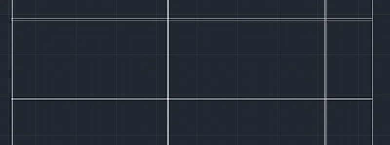
8. Type 'TR' in command line and enter to get trim tool
- Trim all unnecessary lines
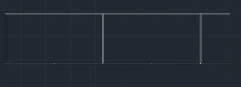
9. Type 'HATCH' in the command line and press enter to get hatch tool
- Draw a closed rectangle outside of the wardrobe for hatching the wall surface
- Pick internal point: Click inside the new rectangle (ANSI31; Hatch Transparency: 42)
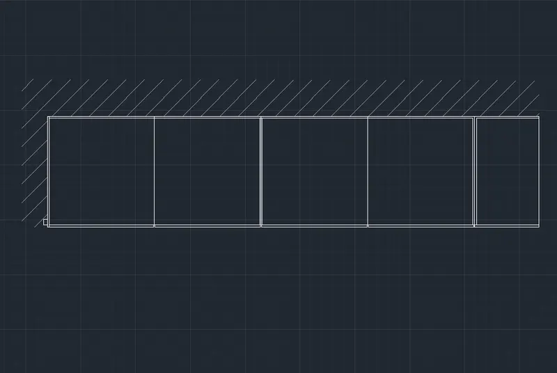
10. Draw the door
- Using 'CIRCLE', 'LINE', COPY' and 'MIRROR' tool, draw and place the door at appropriate place as per the design
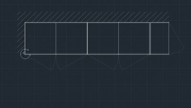
11. Type 'CO' in command line and enter to get copy tool
- Select objects: Select the front elevation wardrobe
- Specify base point or [Displacement/mOde] : Select the left bottom corner point of the front elevation wardrobe
- Specify second point or [Array] : Place the objects at some distance in x direction
- Specify second point or [Array/Exit/Undo] : *Cancel*
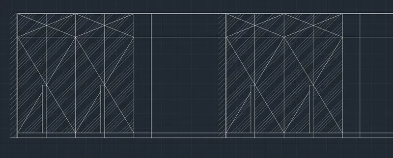
12. Type 'TR' in command line and enter to get trim tool
- Trim all unnecessary lines
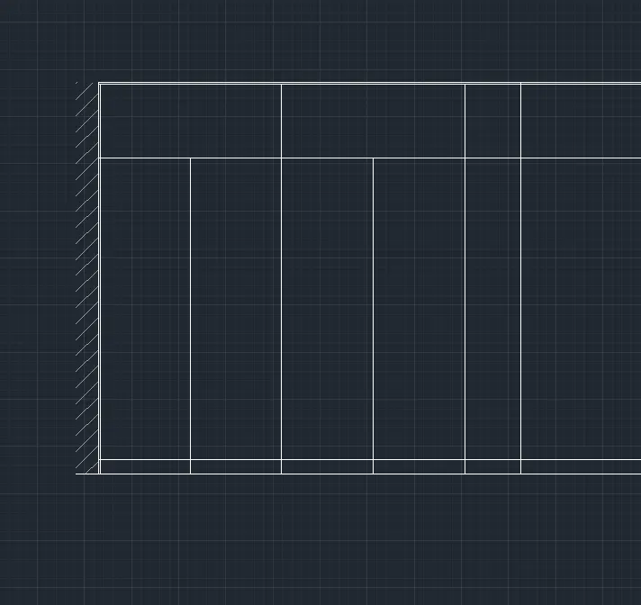
13. Type 'OFFSET' in command line and enter to get offset tool
- Specify offset distance or [Through/Erase/Layer]: 20
- Select object to offset or [Exit/Undo]: Select all the objects to offset 20
- Specify point on side to offset
- Select object to offset or [Exit/Undo] : *Cancel*
- Specify offset distance or [Through/Erase/Layer]: 10
- Select object to offset or [Exit/Undo]: Select all the objects to offset 10
- Specify point on side to offset
- Select object to offset or [Exit/Undo] : *Cancel*
- Specify offset distance or [Through/Erase/Layer]: 20
- Select object to offset or [Exit/Undo]: Select all the objects to offset 20
- Specify point on side to offset
- Select object to offset or [Exit/Undo] : *Cancel*
- Specify offset distance or [Through/Erase/Layer]: 300
- Select object to offset or [Exit/Undo]
- Specify point on side to offset or [Exit/Multiple/Undo] :
- Select object to offset or [Exit/Undo] :
- Specify point on side to offset or [Exit/Multiple/Undo] : 20
- Select object to offset or [Exit/Undo] :
- Specify point on side to offset or [Exit/Multiple/Undo] : 300
- Select object to offset or [Exit/Undo] :
- Specify point on side to offset or [Exit/Multiple/Undo] : 20
- Select object to offset or [Exit/Undo] :
- Specify point on side to offset or [Exit/Multiple/Undo] : 300
- Select object to offset or [Exit/Undo] :
- Specify point on side to offset or [Exit/Multiple/Undo] : 20
- Select object to offset or [Exit/Undo] :
- Specify point on side to offset or [Exit/Multiple/Undo] : 1180
- Select object to offset or [Exit/Undo] :
- Specify point on side to offset or [Exit/Multiple/Undo] : 20
- Select object to offset or [Exit/Undo] :
- Specify point on side to offset or [Exit/Multiple/Undo] : 20
- Select object to offset or [Exit/Undo] : *Cancel*
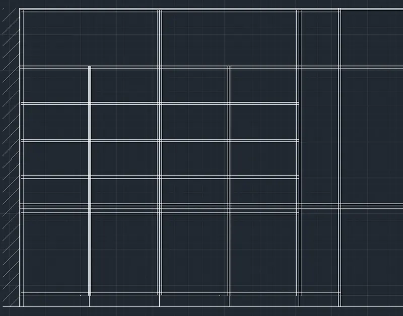
14. Type 'TR' in command line and enter to get trim tool
- Trim all unnecessary lines
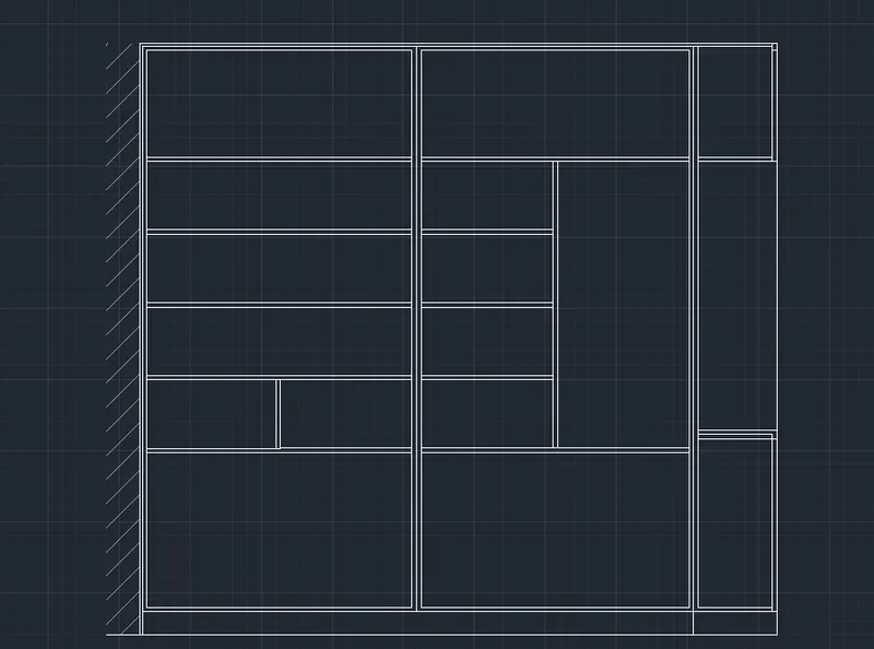
15. Type 'OFFSET' in command line and enter to get offset tool
- Specify offset distance or [Through/Erase/Layer]: 20
- Select object to offset
- Specify point on side to offset
- Select object to offset or [Exit/Undo] : *Cancel*
- Specify offset distance or [Through/Erase/Layer]: T
- Select object to offset
- Specify point on side to offset
- Specify offset distance or [Through/Erase/Layer]: 50
- Select object to offset
- Specify point on side to offset
- Specify offset distance or [Through/Erase/Layer]: T
- Select object to offset
- Specify point on side to offset
- Specify offset distance or [Through/Erase/Layer]: 50
- Select object to offset
- Specify point on side to offset
- Specify offset distance or [Through/Erase/Layer]: T
- Select object to offset
- Specify point on side to offset
- Specify offset distance or [Through/Erase/Layer]: 50
- Select object to offset
- Specify point on side to offset
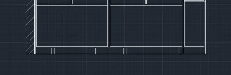
16. Draw the inside of the wardrobe
- Draw the drawer using 'OFFSET', 'RECTANGLE', 'MIRROR', 'COPY' tools
- Draw the designs shown in the figure
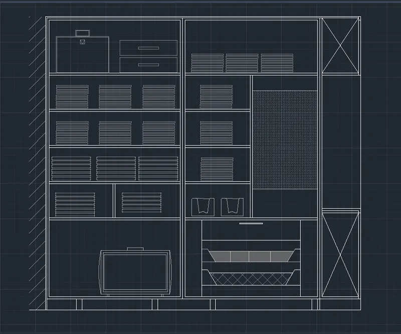
17. Draw side elevation
- Type 'REC' in command line and enter to get rectangle, draw a rectangle of 630x2600
- Type 'M' in command line and enter to get move tool, move the rectangle and align it with ortho mode
- Select the rectangle and click explode on the panel.
- Type 'OFF' in command line and enter to get offset tool
- Specify offset distance: 20
- elect object to offset or [Exit/Undo] : Select all the objects to offset 20
- Specify point on side to offset or [Exit/Multiple/Undo] : 520
- Select object to offset or [Exit/Undo] :
- Specify point on side to offset or [Exit/Multiple/Undo] : 1180
- Select object to offset or [Exit/Undo] :
- Specify point on side to offset or [Exit/Multiple/Undo] : 30
- Select object to offset or [Exit/Undo] :
- Select object to offset or [Exit/Undo] :
- Specify point on side to offset or [Exit/Multiple/Undo] : 100
- Select object to offset or [Exit/Undo] : *Cancel*
- Type 'TR' in command line and enter to get trim tool, trim all unnecessary lines
- Type 'L' in the command line and press enter to get line tool
- Draw the line to mark the door opening direction
- Draw the line and form a rectangle outside the wardrobe for hatching
- Type 'HATCH' in the command line and press enter to get hatch tool
- Pick internal point: Click inside the new rectangle (ANSI31; Hatch Transparency: 42)
- Pick internal point: Click inside the wardrobe (ANSI34; Hatch Transparency: 42)
- Delete the rightside line of rectangle outside the wardrobe
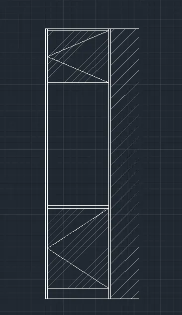
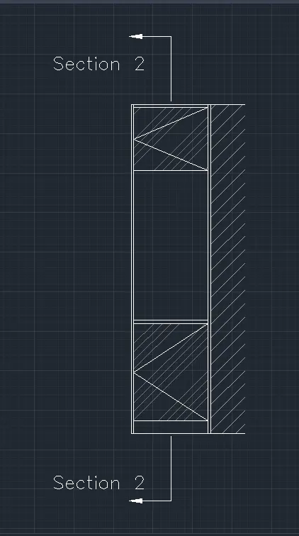
18. Mark the section 1 and section 2 in front elevation and side elevation respectively
-
Type 'QLEADER' in the command line and press enter to get pointer tool
- Specify first leader point: Point near the wardrobe to show section
- Specify next point: 500 in the y direction
- Specify next point: 300 in the -x direction
- Specify text width: Press enter
- Enter first line of annotation text : Section 1
- Use 'COPY', 'MIRROR', 'ROTATE' tool, place the leader to the opposite side
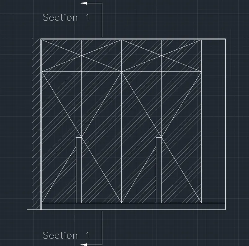
- Type 'QLEADER' in the command line and press enter to get pointer tool
- Specify first leader point: Point near the wardrobe to show section
- Specify next point: 500 in the y direction
- Specify next point: 300 in the -x direction
- Specify text width: Press enter
- Enter first line of annotation text : Section 2
- Use 'COPY', 'MIRROR', 'ROTATE' tool, place the leader to the opposite side
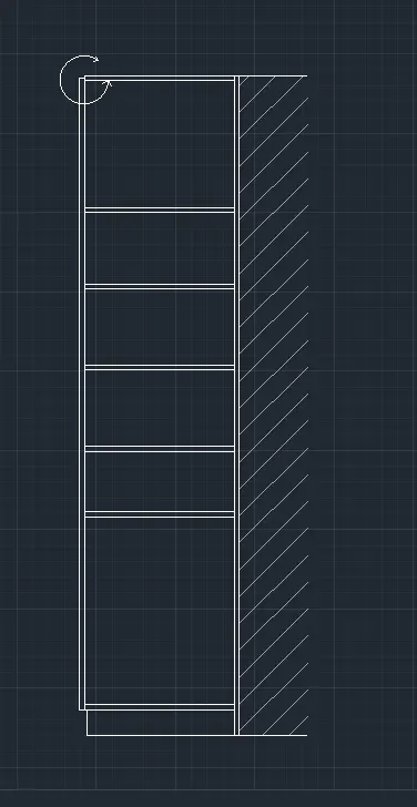
19. Draw Section-1
- Type 'REC' in command line and enter to get rectangle, draw a rectangle of 630x2600
- Type 'M' in command line and enter to get move tool, move the rectangle and align it with ortho mode
- Select the rectangle and click explode on the panel.
- Type 'OFF' in command line and enter to get offset tool
- Select object to offset or [Exit/Undo] :
- Specify through point or [Exit/Multiple/Undo] : 20
- Select object to offset or [Exit/Undo] :
- Specify through point or [Exit/Multiple/Undo] : 20
- Select object to offset or [Exit/Undo] :
- Specify through point or [Exit/Multiple/Undo] : 20
- Select object to offset or [Exit/Undo] :
- Specify through point or [Exit/Multiple/Undo] : 520
- Select object to offset or [Exit/Undo] :
- Specify through point or [Exit/Multiple/Undo] : 20
- Select object to offset or [Exit/Undo] :
- Specify through point or [Exit/Multiple/Undo] : 1180
- Select object to offset or [Exit/Undo] :
- Specify through point or [Exit/Multiple/Undo] : 20
- Select object to offset or [Exit/Undo] :
- Specify through point or [Exit/Multiple/Undo] : 100
- Select object to offset or [Exit/Undo] :
- Specify through point or [Exit/Multiple/Undo] : 20
- Select object to offset or [Exit/Undo] : *Cancel*
- Type 'RAY' in command line and enter to get ray line
- Select all lines from front elevation to get in the section 1
- Type 'TR' in command line and enter to get trim tool, remove all unnecesary lines
- Type 'C' in command line and enter to get circle, draw a circle to show rotation of door, Using 'LINE', 'TRIM' tools, draw arrows and trim unnecessary lines amd arcs
- Type 'L' in the command line and press enter to get line tool
- Draw the line and form a rectangle outside the wardrobe for hatching
- Type 'HATCH' in the command line and press enter to get hatch tool
- Pick internal point: Click inside the new rectangle (ANSI31; Hatch Transparency: 42)
- Delete the rightside line of rectangle outside the wardrobe
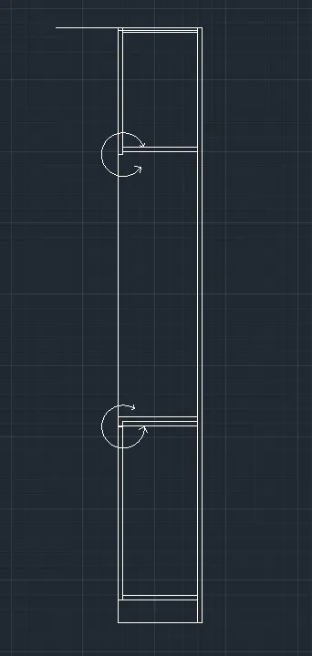
20. Draw Section-2
- Type 'REC' in command line and enter to get rectangle, draw a rectangle of 6365x2600
- Type 'M' in command line and enter to get move tool, move the rectangle and align it with ortho mode
- Select the rectangle and click explode on the panel.
- Type 'RAY' in command line and enter to get ray line
- Select all lines from front carcase elevation to get in the section 2
- Type 'OFF' in command line and enter to get offset tool
- Specify offset distance or [Through/Erase/Layer]: T
- Select object to offset or [Exit/Undo] :
- Specify through point or [Exit/Multiple/Undo] : 12
- Select object to offset or [Exit/Undo] :
- Specify through point or [Exit/Multiple/Undo] : 20
- Select object to offset or [Exit/Undo] :
- Specify through point or [Exit/Multiple/Undo] : 20
- Select object to offset or [Exit/Undo] : *Cancel*
- Type 'TR' in command line and enter to get trim tool, remove all unnecesary lines
- Type 'C' in command line and enter to get circle, draw a circle to show rotation of door, Using 'LINE', 'TRIM' tools, draw arrows and trim unnecessary lines amd arcs
21. Texts, annotation and layers
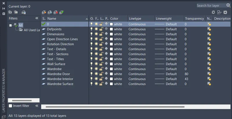
- Type 'LAYER' in command line and enter to get layer properties
- Create a new layer for each segments
- Type 'MTEXT' in command line and enter to type text
- Different types of texts are created for each layer as shown in the above figure
- Type 'DIM' in command line and enter to get dimension lines
- All dimensions are given in dimension layer as shown in the above figure
RESULT
The elevation and details of a wardrobe is drawn using various tools in AutoCAD.
Q2
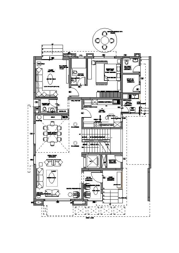
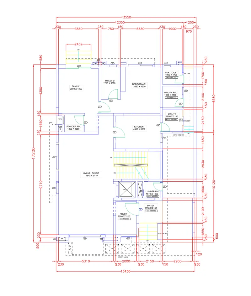
Draw the floor plan as shown in the Figure. Use the proper drafting tools to sketch the plan. Do not hatch or draw the furniture. You need to draw the floor plan with the following:
Note: You can also import the Floor_Plan.pdf into your current drawing and start working on the project. You need to scale the imported pdf file using reference option. All dimensions are in mm.
- Walls (Exterior and Interior)
Wall Thickness: Exterior Wall- 230mm, Interior Wall: 150 mm (Wherever Required)
- Doors and Windows: Assume the size of the doors and window.
2.1 Stairs: Tread-300mm, Riser-150mm
- Insert Text wherever required
- Insert the dimensions using proper dimension techniques
AIM
To draw a floor plan as shown in figure using proper drafting tools
PROCEDURE
Open the AutoCAD Application and create a new AutoCAD file with imperial settings. Set the units in 'Decimal' and precision (0).
1. Importing the Floor Plan into the AutoCAD
- Type 'IMP' in the command line and enter to get import file
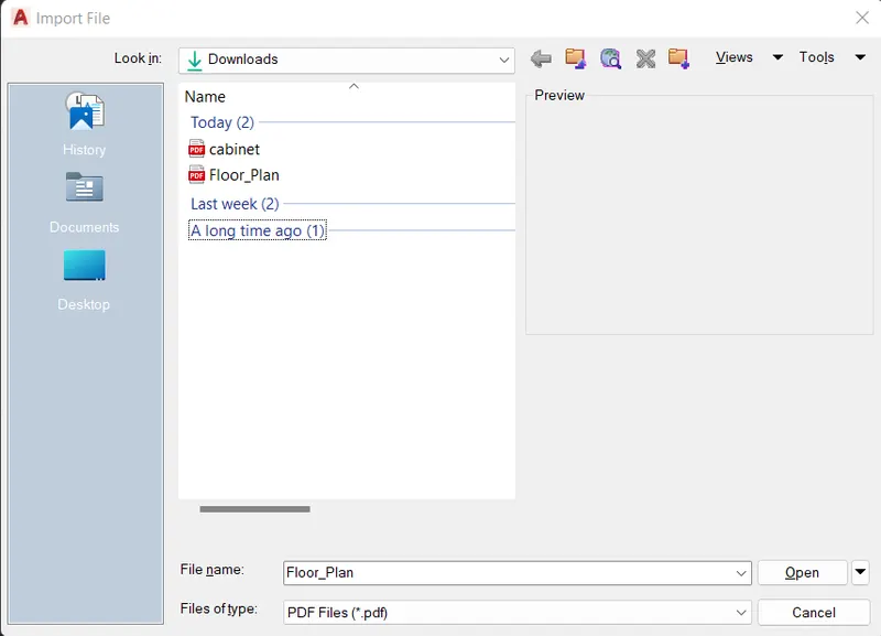
- Select 'Floor_Plan.pdf' and press open to get Import PDF window, click on 'Create object layers'
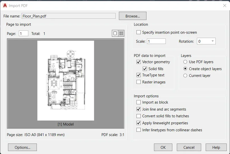
- Press 'OK' to import the pdf to AutoCAD
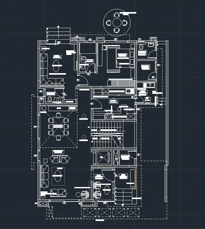
2. Scale the imported pdf
- Type 'SC' in the command line and enter to get scale tool
- Select objects: Select all objects
- Specify base point
- Specify scale factor or [Copy/Reference]: r
- Specify reference length <1.0000>: 1
- Specify new length or [Points]: 75.1962

3. Insert dimensions
- Type 'DIM' in command line and enter to get dimension line
- Press 'c' to continue dimension upto the desired point
- Dimension all the essential points
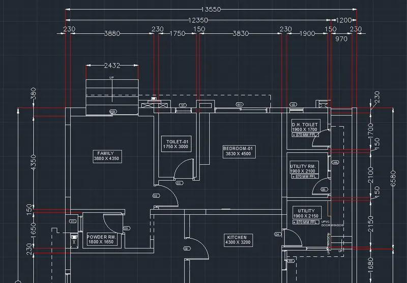
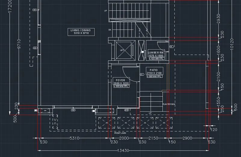
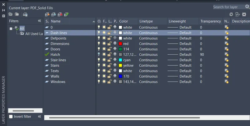
4. Apply layers
- Type 'LAYER' in command line and enter to get layer properties
- Create a new layer for each segments
RESULT
The floor plan is drawn using proper drafting tools available in the AutoCAD software. All dimensions are in 'mm'.
Q3
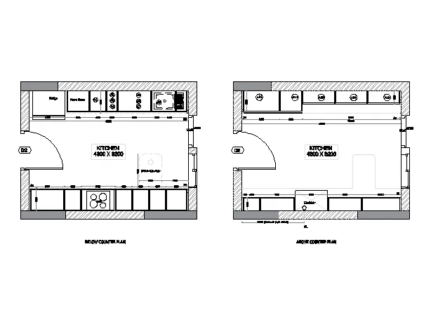
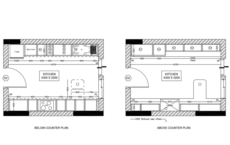
Create the Kitchen Layout as shown in the Figure below. Also, use proper dimension techniques to dimension the kitchen layout. Also, insert text wherever required. All dimensions are in mm.
AIM
To create the kitchen layout as shown in the figure below using proper dimension techniques
PROCEDURE
Open the AutoCAD Application and create a new AutoCAD file with imperial settings. Set the units in 'Decimal' and precision (0).
1. Draw the below counter plan
- Type 'REC' in the command line and enter to get rectangle
- Specify first corner point
- Specify other corner point or [Area/Dimensions/Rotation]: @4300,3200
- Type 'OFF' in the command line and enter to get offset tool
- Specify offset distance or [Through/Erase/Layer] : 230
- Select object to offset: Select the rectangle
- Specify point on side to offset or [Exit/Multiple/Undo] : Outside the rectangle
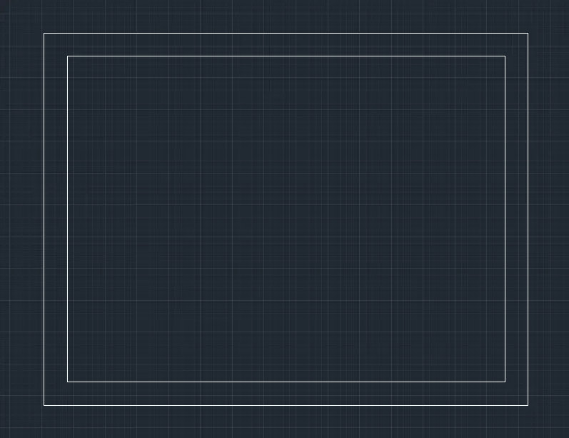
- Select the rectangle and click explode on the panel.
- Type 'OFF' in the command line and enter to get offset tool
- Offset essential lines as shown in the design
- Type 'TR' in the command line and enter to get trim tool, trim all unnecessary lines
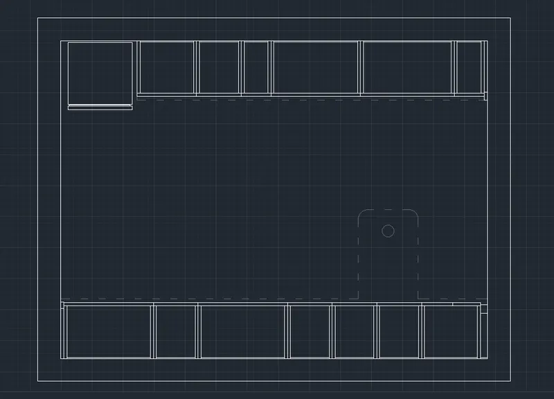
- Draw the door
- Using 'LINE', 'CIRCLE', 'TRIM', 'HATCH', 'COPY', 'MIRROR' tools, create doors
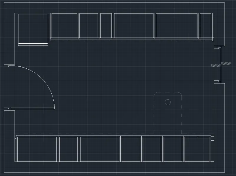
- Draw the window
- Using 'LINE', 'RECTANGLE', 'COPY' tools, draw window
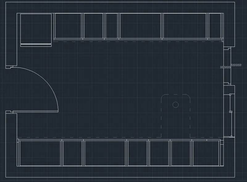
- Draw the sink and hob
- Using 'LINE', 'RECTANGLE', 'CIRCLE', 'ARC', 'FILLET', 'COPY' tools, draw the sink
- Using 'RECTANGLE', 'CIRCLE' tools, draw the hob
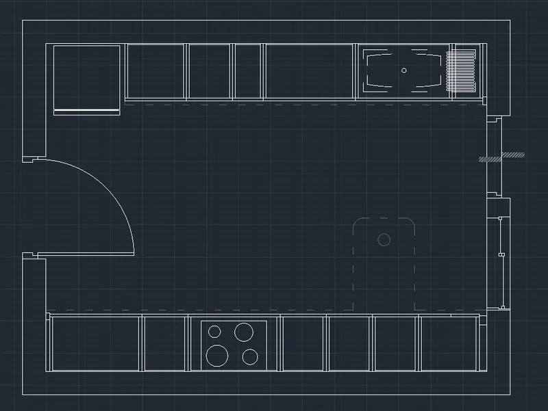
- Type 'H' in the command line and enter to get hatch tool
- Pick internal point: (SOLID)
- Pick internal point: (ANSI31)

2. Draw the above counter plan
- Type 'CO' in the command line and enter to get copy tool
- Select all objects and paste to other side with ortho mode
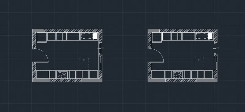
- Type 'E' in the command line and enter to get erase tool
- Select the objects to erase as per the above counter plan
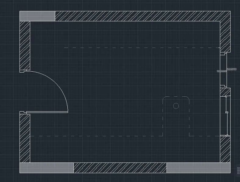
- Type 'OFF' in the command line and enter to get offset tool
- Select the objects to offset as per the above counter plan
- Type 'Tr' in the command line and enter to get trim tool
- Select the objects to trim as per the above counter plan
- Type 'C' in the command line and enter to get circle
- Draw a circle for chimney
- Type 'L' in the command line and enter to get line tool
- Draw lines according to the above counter plan
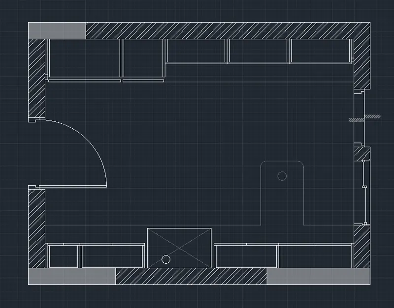
3. Type 'DIM' in command line and enter to get dimension line
- Mark all the dimensions, type 'c' to continue dimensions
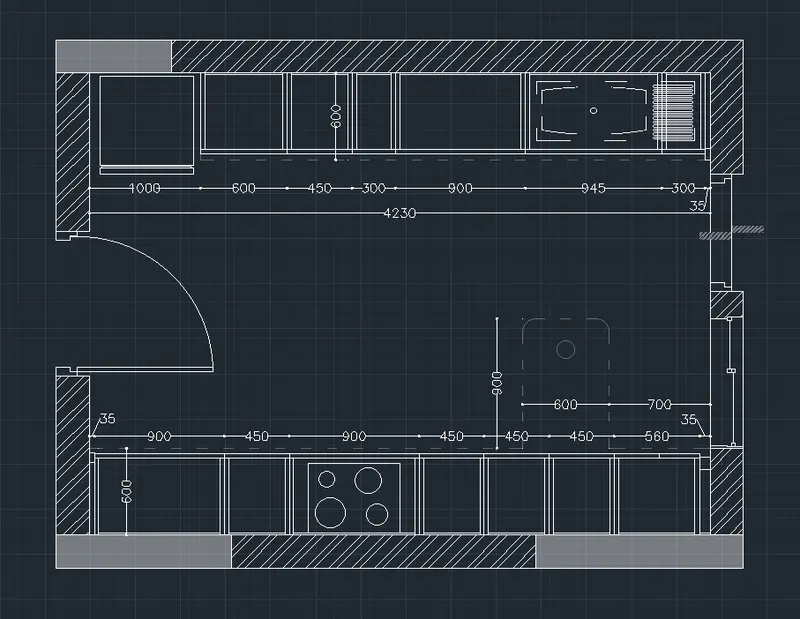
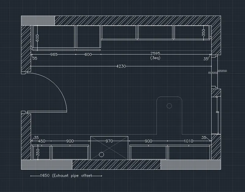
4. Insert texts
- Type 'MTEXT' in command line and enter to get text tool, type all necessary details
- Type 'C' in command line and enter to get circle, draw circle around some text as per the plan
- Type 'PLINE' in command line and enter to get polyline tool, draw a hexagon around 'D2'
- Type 'REC' in command line and enter to get rectangle, draw a rectangle around the main dimension
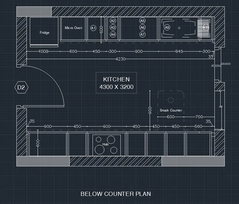
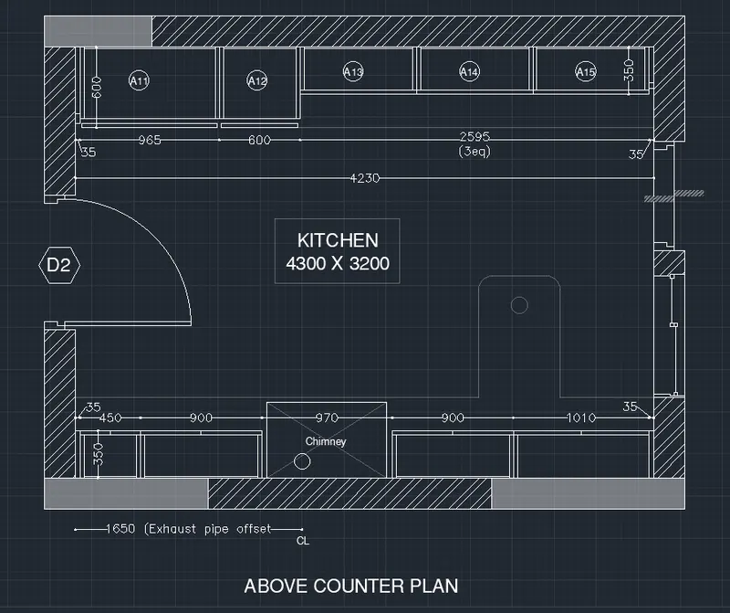
RESULT
The kitchen layout is drawn as shown in the figure using proper dimension techniques. All dimensions are in 'mm'
Q4
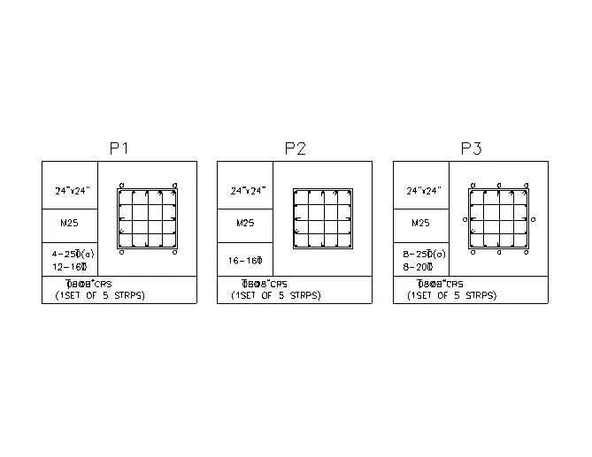
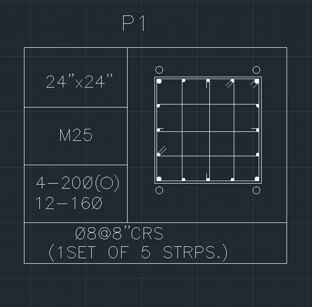
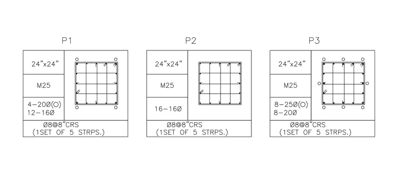
Sketch the column details as shown in Figure. Insert dimensions and text in the figure. Refer to the bar sizes from the schedule.
8mm ---- 0.31 Inches
25mm--- 1 inches
16mm—0.62 inches
AIM
To sketch the column details as shown in figure
PROCEDURE
Open the AutoCAD Application and create a new AutoCAD file with imperial settings. Set the units in 'Engineering' and precision (0).
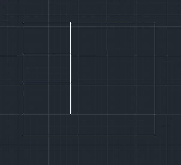
1. Draw the column schedule table
- Using 'LINE', 'RECTANG', the table for column schedule is created
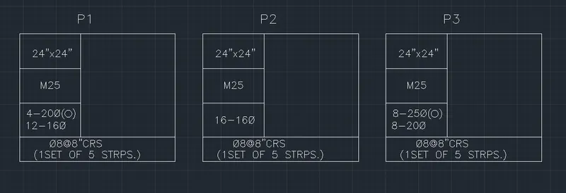
2. Provide annotations given in the figure
- Using 'MTEXT' tool, type all the labels given in the figure
- Using 'SCALE', 'MOVE', and 'COPY' tool, place the text in the appropriate box as shown
3. Draw the columns
P1:
- Using 'RECTANG' tool, draw a rectangle of 24"x24"
- Using 'OFFSET' tool, offset cover distance 0.5"
- Using 'CIRCLE' tool, draw a circle of dia 20mm and 16mm
- Using 'CIRCLE' tool, draw a circle to indicate main bars
- Using 'COPY', 'MIRROR', 'DIVIDE' tool, place the circle as per the given drawing
- Using 'LINE' tool, draw the stirrups shown in figure
- Type 'HATCH' in command line and enter to get hatch tool
- Pick internal point: Select all bars (SOLID)
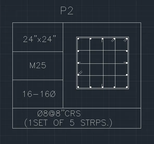
P2:
- Using 'RECTANG' tool, draw a rectangle of 24"x24"
- Using 'OFFSET' tool, offset cover distance 0.5"
- Using 'CIRCLE' tool, draw a circle of dia 16mm
- Using 'COPY', 'MIRROR', 'DIVIDE' tool, place the circle as per the given drawing
- Using 'LINE' tool, draw the stirrups shown in figure
- Type 'HATCH' in command line and enter to get hatch tool
- Pick internal point: Select all bars (SOLID)
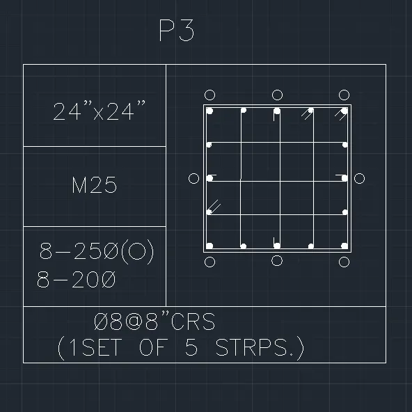
P3:
- Using 'RECTANG' tool, draw a rectangle of 24"x24"
- Using 'OFFSET' tool, offset cover distance 0.5"
- Using 'CIRCLE' tool, draw a circle of dia 25mm and 20mm
- Using 'CIRCLE' tool, draw a circle to indicate main bars
- Using 'COPY', 'MIRROR', 'DIVIDE' tool, place the circle as per the given drawing
- Using 'LINE' tool, draw the stirrups shown in figure
- Type 'HATCH' in command line and enter to get hatch tool
- Pick internal point: Select all bars (SOLID)
RESULT
The column details is sketched as shown in figure.
Q5
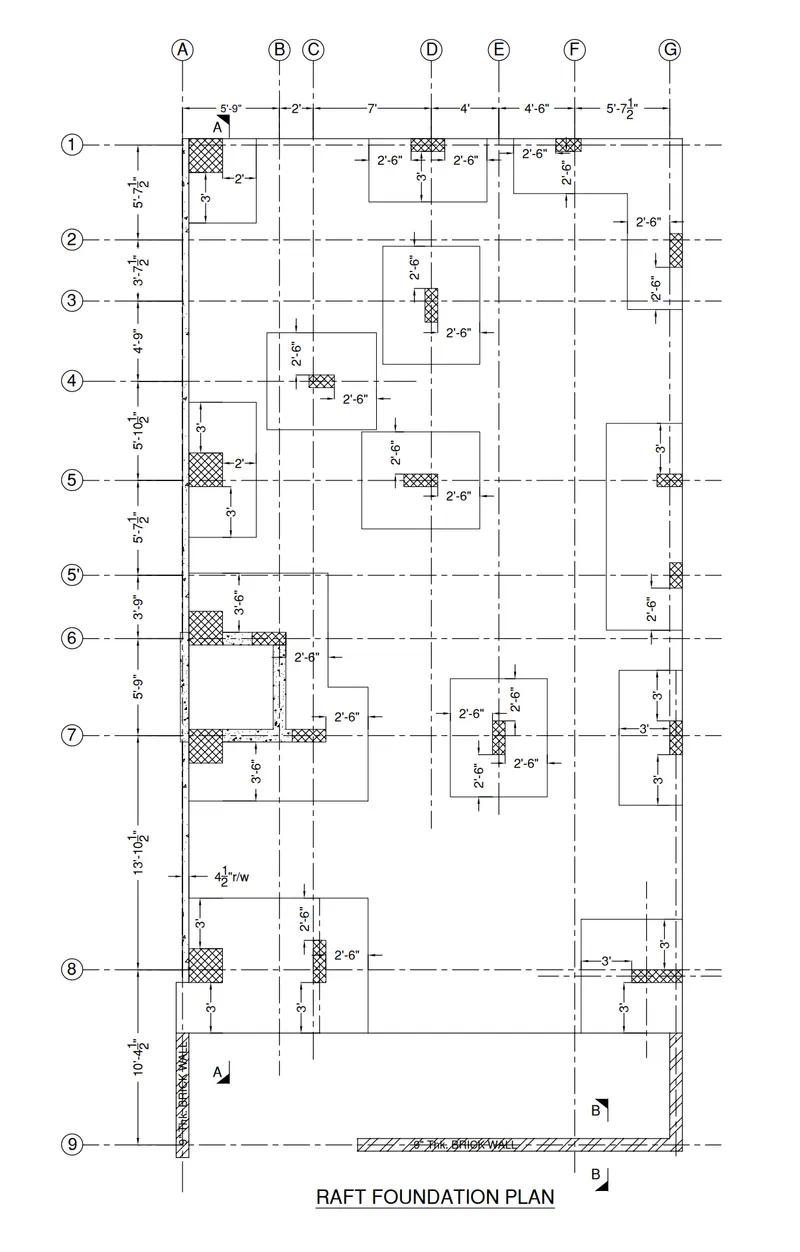
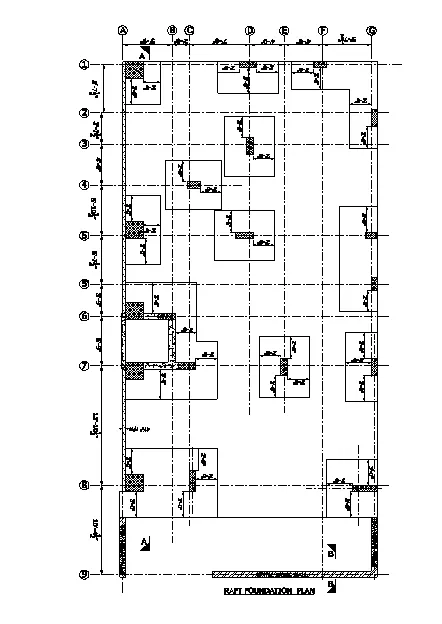
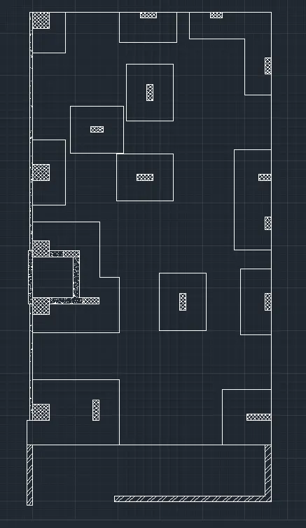
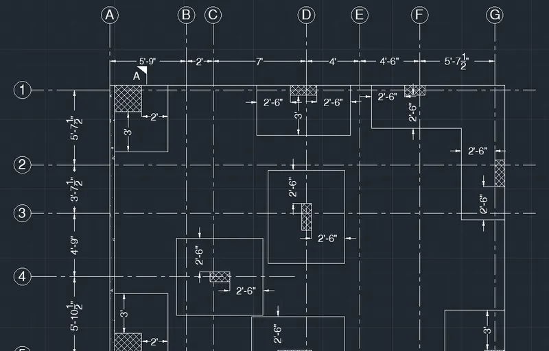
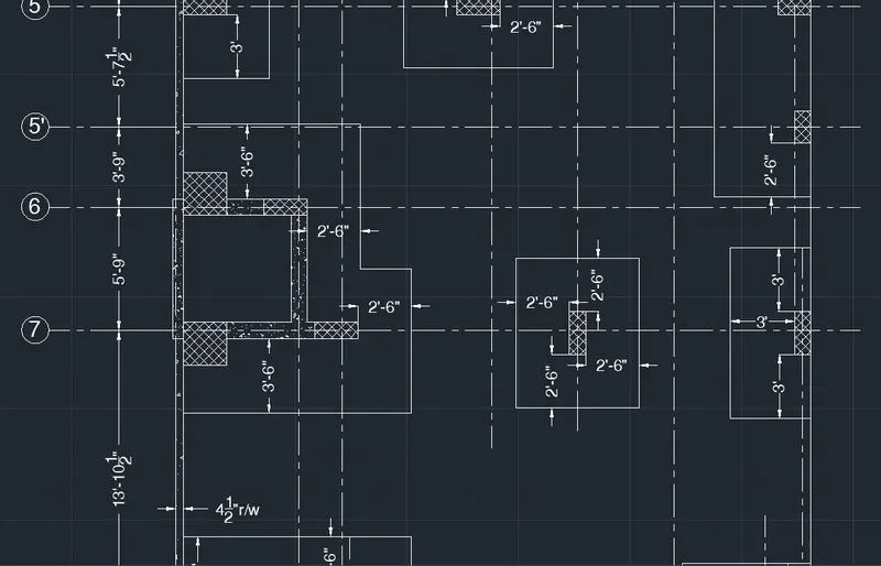
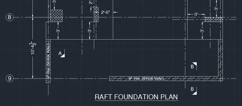
Draw the Raft Layout as shown in the Figure. Assume the column size as per your knowledge. You can take the sizes as: 24”x24”, 9” x 24”, 9” x 18”, and 9’ x 24”. You can import the raft_foundation.pdf to ensure the missing dimensions.
AIM
To draw the raft foundation plan as shown in the figure
PROCEDURE
Open the AutoCAD Application and create a new AutoCAD file with imperial settings. Set the units in 'Architectural' and precision (0'-0 1/2").
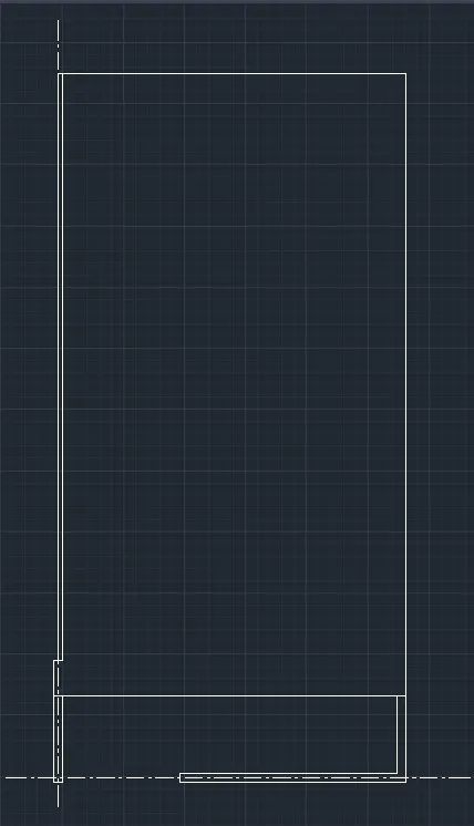
1. Create an outline for raft foundation plan
- Type 'LA' in the command line and enter to get layer properties
- Create a new layer "Wall"
- Type 'XL' in the command line and enter to get xline tool
- Create a horizontal and vertical line
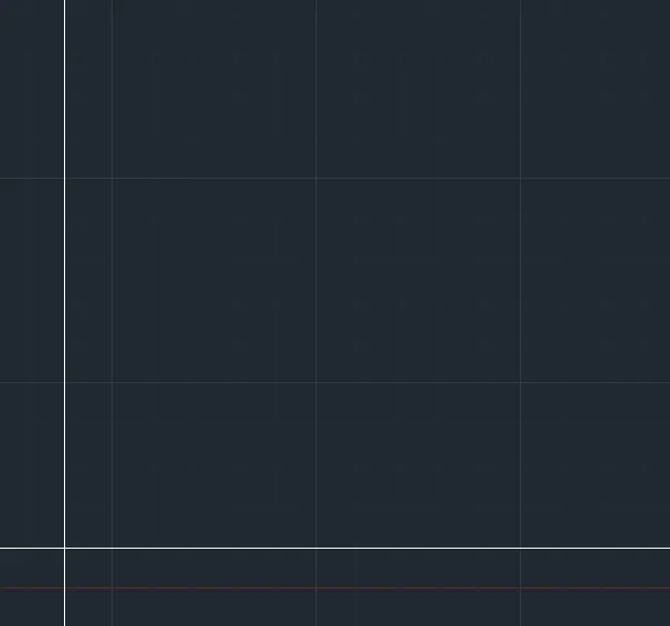
- Type 'OFF' in the command line and enter to get offset tool
- Offset all essential lines
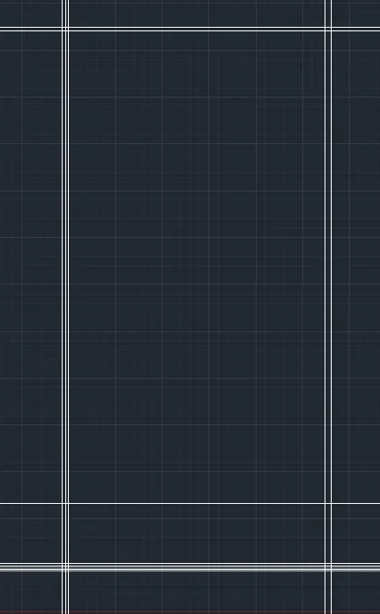
- Type 'TR' in the command line and enter to get trim tool
- Trim all unnessecary lines
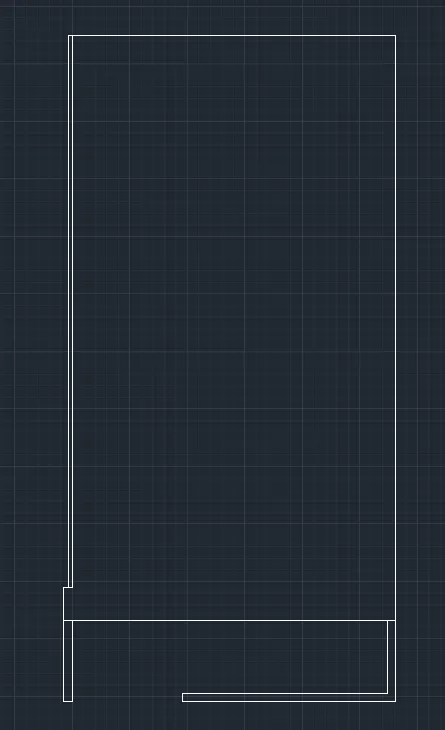
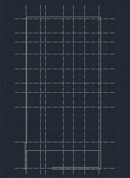
2. Create grid lines in the raft foundation plan
- Type 'LA' in the command line and enter to get layer properties
- Create a new layer "Grid Lines" with linetype (CENTER)
- Type 'L' in the command line and enter to get line tool
- Draw vertical and horizontal line from bottom for offset
- Type 'OFF' in the command line and enter to get offset tool
- Offset all essential lines
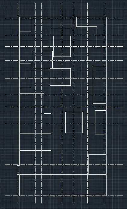
3. Create footings in the raft foundation plan
- Type 'LA' in the command line and enter to get layer properties
- Create a new layer "Footing"
- With 'IMPORT' tool, import the "raft.pdf" and take the measurements of the footing
- Type 'PLINE' in the command line and enter to get polyline
- Draw all the footing as per the given figure with the help of imported file
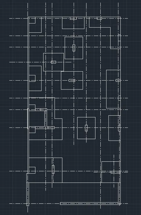
4. Create column in the raft foundation plan
- Type 'LA' in the command line and enter to get layer properties
- Create a new layer "Column"
- Type 'REC' in the command line and enter to get rectangle
- Specify first point: tra
- First tracking point: Track the lines according to the figure
- Press enter to get rectangle, draw the column with given standard sizes
- Repeat the above procedure to draw all the columns
- Type 'OFF' in the command line and enter to get offset tool
- Offset "Grid lines" according to the columns drawn
- Type 'TR' in the command line and enter to get trim tool
- Trim unnecessary grid lines according to the design
5. Hatch the columns, brick walls, r/w of the raft foundation plan
- Type 'LA' in the command line and enter to get layer properties
- Create a new layer "Hatch"
- Turn off the "Grid lines" layer for proper hatching
- Type 'H' in the command line and enter to get hatch tool
- Pick internal point: Select all the columns (ANSI37)
- Pick internal point: Select all the 9" brick walls (ANSI32)
- Pick internal point: Select all the 4.5" concrete wall (AR-CONC, Scale: 2.9)
- Pick internal point: Select all the 9" concrete wall (AR-CONC, Scale: 1.5)
6. Insert dimensions
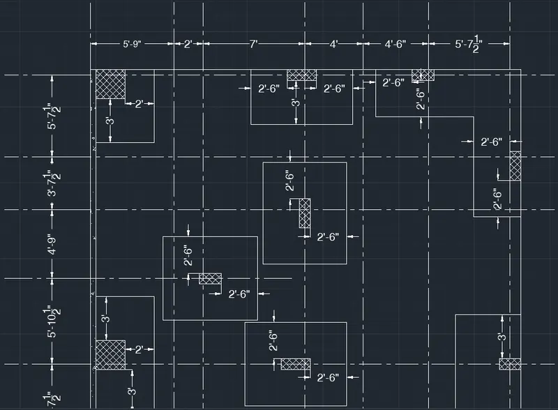
- Type 'LA' in the command line and enter to get layer properties
- Create a new layer "Dimension"
- Turn on the "Grid lines" layer for proper dimensioning
- Type 'DIM' in the command line and enter to get dimension line
- Mark all necessary dimensions as shown in the figure
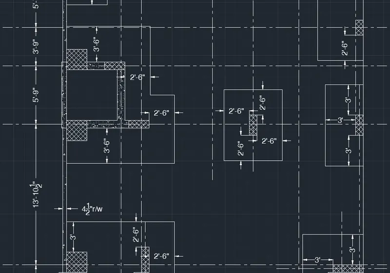
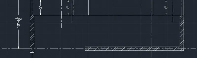
7. Insert texts and designs
- Type 'LA' in the command line and enter to get layer properties
- Create a new layer "Text"
- Type 'C' in the command line and enter to get circle
- Draw a circle to contain text and numbers indicating gridlines
- Type 'TEXT' in the command line and enter to get single line text
- Type text and numbers inside the circle, 'COPY', 'TEXTEDIT' tools are used
- Type text wherever required as per the plan
- Type 'L' in the command line and enter to get line
- Draw lines to show the section arrows, 'MIRROR', 'MOVE' tools are used
- Type 'MTEXT' in the command line and enter to get multi line text
- Type text wherever required as per the plan
RESULT
The raft foundation plan is drawn as per the given figure.