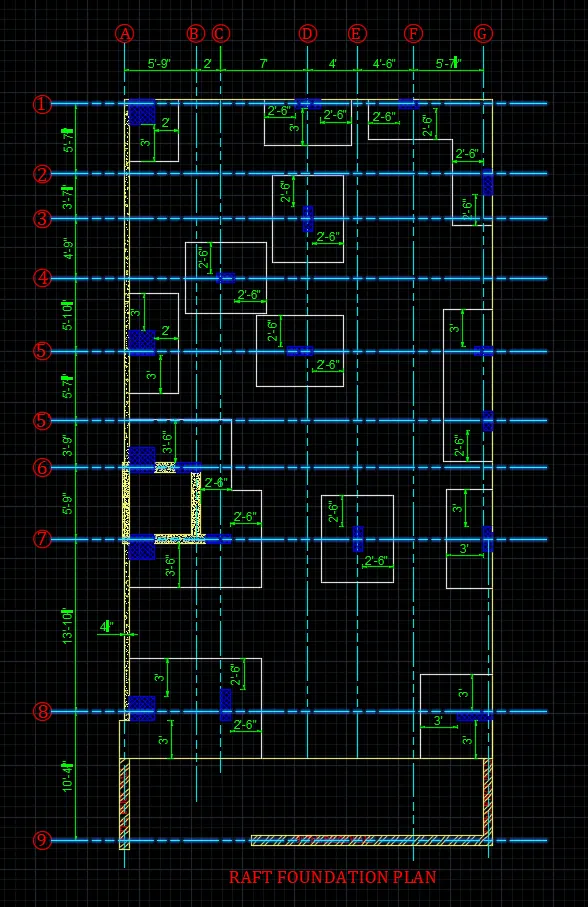
Creating a Wardrobe detailed drawing, Floor Plan, Kitchen Layout and Column Detail using AutoCad
1) AIM: Draw the elevation and details of a wardrobe
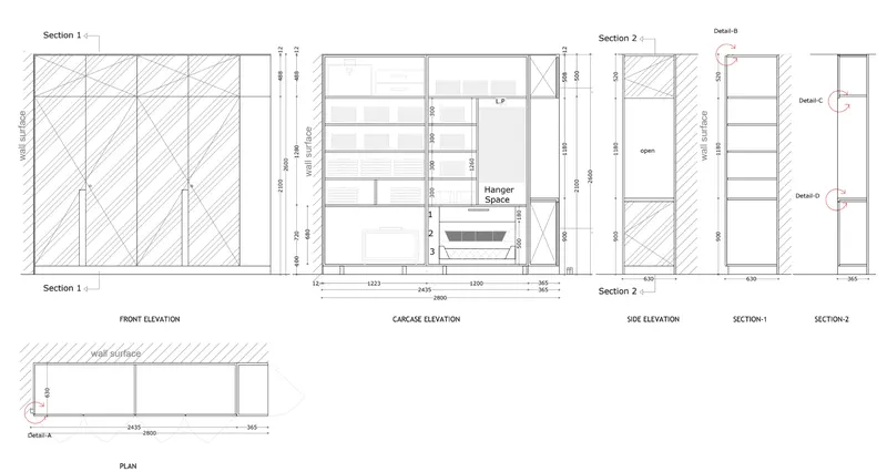
Procedure:
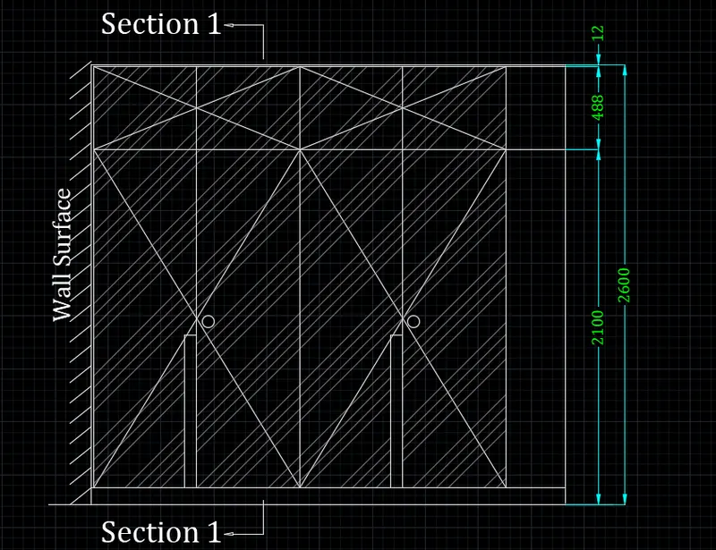
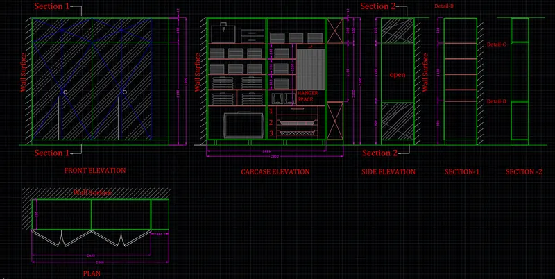
Step 1: Front Elevation
- Type 'un' and set the units to 'mm'
- Use rectangle command and create a rectangle of
- length = 2800
- width = 2600
- From the bottom horizontal line take an offset of 100 and then from that line again an offset of 2000 and then 488
- From the left vertical line take an offset of 12 and then 4 offset simultaneously spacing of 608.75 each
- Now use line command to connect the points to make crossing lines
- Trim the rest part
- Use circle command to make handles
- Now use 'hatch' command and hatch the figure with "ANS134"
- Now provide dimensions using dimlinear command and provide text using mtext command
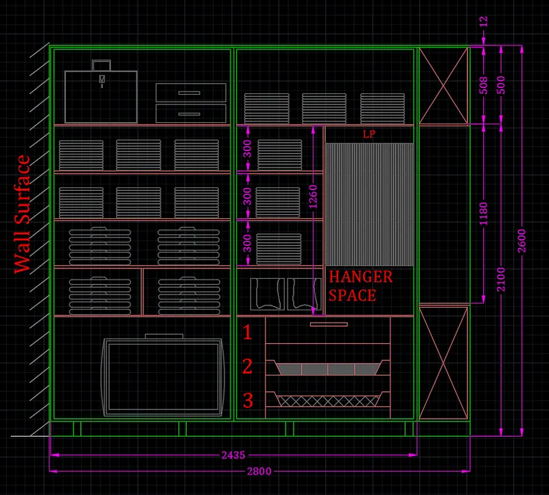
Step 2: Carcase Elevation
- Use copy command and copy the figure right to the previous one
- Use erase option and remove all the things in inner portion except the boundry and wall surface
- Now use offset command and make a rectangle inside the two box
- Use line command and create drawers, cabinet and objects.
- using mtext give text
- Now provide dimension as per drawing
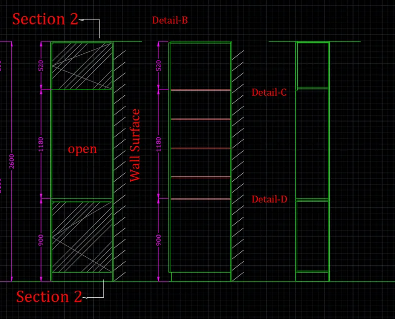
Step 3: Side Elevation, Section 1 and Section 2
- Use rec command and draw rectangle of size 520x630,1180x630, 900x630.
- Repeat the above process
- Repeat the rec command and create rectangle of dimension 520x365, 1180x365, 900x365
- use line and offset commad to make other lines
- Use dimension command to give proper dimensions
Step 4: Plan
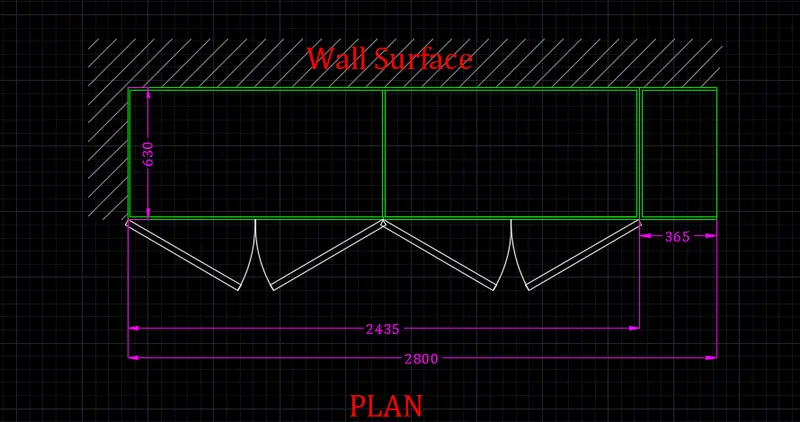
- Create a rectangle of dimension 630x2800
- use line and offset command
- Give dimensions as required
Result:
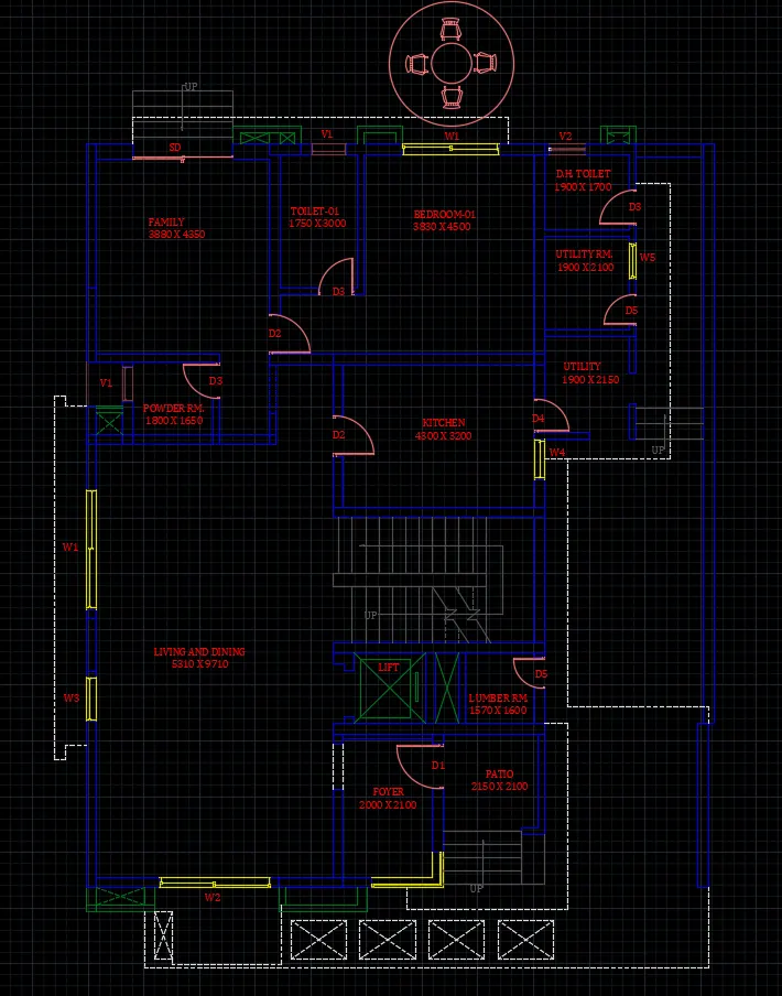
2) AIM: Draw the floor plan
Procedure:
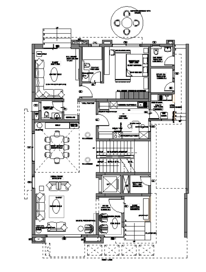
Step 1: Creating Layers and setting units
- Use unit command to set units to mm
- Use layer properties option to create respective layers for drawing
Step 2: Creating the Walls
- Select the walls Layer in layers option in home tab
- Use xline and line command to create wall lines
- Now use offset and trim command to create walls
- Thickness of wall
- External wall - 230mm
- Internal Wall - 150mm
Step 3: Create Doors, Windows and Ventilaters
- Select Doors layer
- Use line and arc command to create doors
- Dimension of doors
- D1 - 1000 x 2100 mm
- D2 - 900 x 2100 mm
- D3 - 800 x 2100 mm
- D4 - 750 x 2100 mm
- D5 - 700 x 2100 mm
- SD - 2256 x 2100 mm
- Select windows layer
- Use line command to create windows
- Dimensions of windows
- W1 - 2700 x 1500 mm
- W2 - 2500 x 1500 mm
- W3 - 1000 x 1500 mm
- W4 - 900 x 1500 mm
- W5 - 800 x 1500 mm
- Select ventilaters layer
- Dimension of ventilaters
- V1 - 800 x 500 mm
- V2 - 750 x 500 mm
Step 3: Creating Stairs and canopy
- Use line command to create stairs
- Use offset command to give stairs tread of 300mm
- place the stairs in stair layer
- Use circle command to create canopy structure of radius 1398 and 452
- from design center place chair
- Use polar array to array the chair
Step 4: Creating ducts and dashed lines
- use line command to create ducts wherever provided
- For dashed lines Used line properties option
- select ISO02W100
- Create lines wherever required
Step 5: Providing text and dimensions
- Use dimension command to give proper dimensions
- Use mtext to provide text
Result:
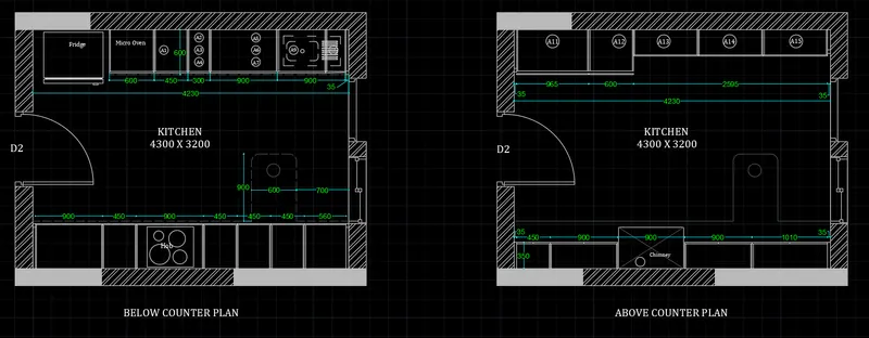
3) AIM: Create the Kitchen Layout
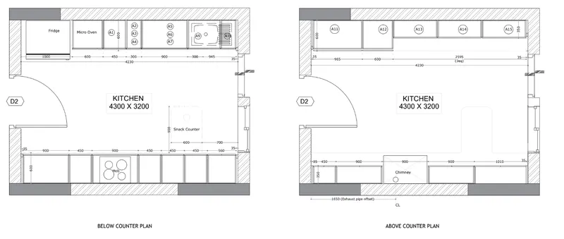
Procedure:
Steps:
- Use rectangle command to create a rectangle of dimension 4230 x 3200
- Use offst command and take an offset of 230mm outwards
- use line and arc command to make doors and trim rest
- Use hatch command to hatch the walls
- Use line commands to make windows
- Use copy command to copy the whole drawing
- now in the first figure
- Use line commad to draw the equipments
- also use the offset command
- Use circle command to draw circle for hob
- Use mt text command to provide text
- Now provide dimensions using linear dimensions
Result:
4) AIM: Sketch the column details
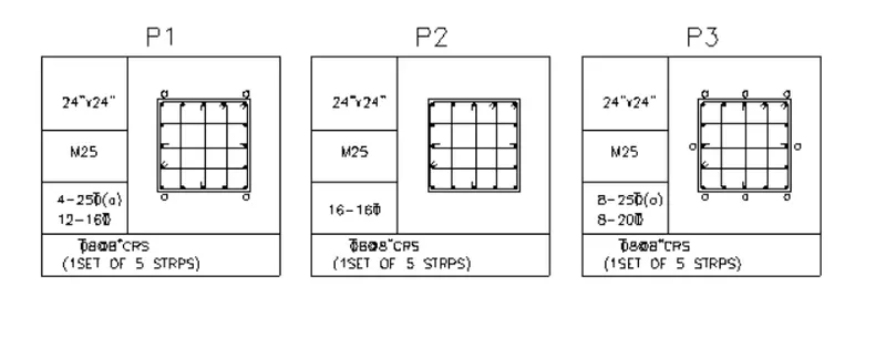
Procedure:
Steps:
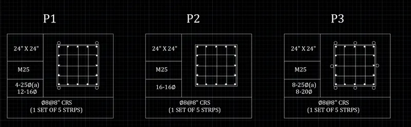
- Use line and rectengle command to create tables
- Use mtext command to enter the text as given in the schedule
- Use line and cirlce command to draw reinforcement
Result:
5) AIM: Draw the Raft Layout
Procedure:
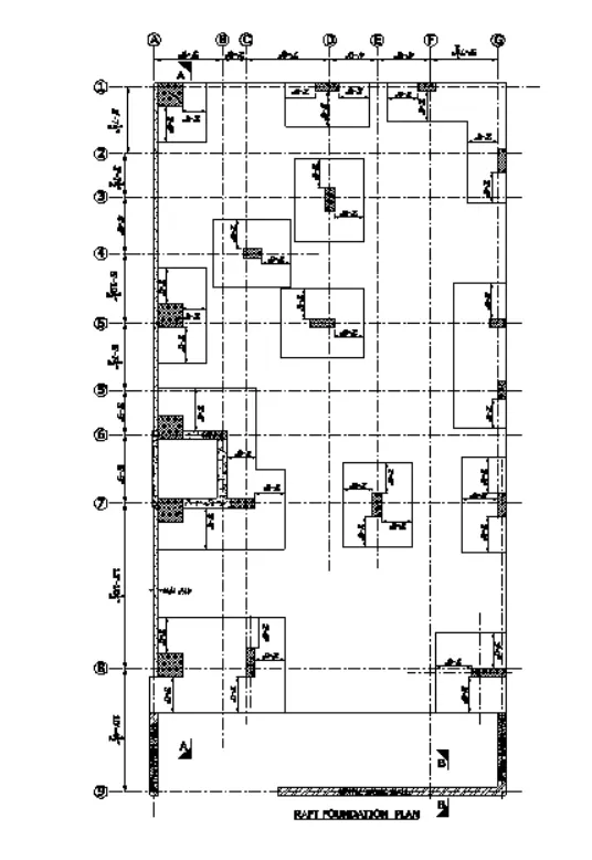
Step 1: Setting Units and page setup
- Use un command to set units in feet inches(Architectural)
- Use limits and zoom command to set page layout
- Create layers for differt things
- Grids
- walls
- columns
- text
- Footing
- Dimensions
Step 2: Creating Grids and walls
- Use xline command to create grid lines with linetype - ACAD_ISO09W100
- Offset of xline in horizontal direction are - 10'-4 1/2", 13'-10 1/2", 5'9", 3'-9", 5'-7 1/2", 5'-10 1/2", 4'-9", 3'-7 1/2", 5'-7 1/2"
- Offset of xline in vertical direction are - 5'-9", 2'-0", 7'-0", 4'-0", 4'-6", 5'-7 1/2"
- Now select the walls layer
- Use line commad to create walls and then offset it at distance 4 1/2"
- Use hatch command to hatch walss with ANS133
- Also create a brick wall of 9" thick using offset commad
Step3: Creating columns and footing
- Use rec command to create colums of dimensions - 24" x 24", 9" x 24", 9"x18", 24"x9", 18"x9",9"x30"
- Use hatch commad to hatch the colums with ANS137
- Use line command to create footing
Step4: Inserting text and providing dimensions
- Use mtext command to insert text and provide neccessary text
- Use dimension command to give proper dimensions
Result: