Creating a Wardrobe detailed drawing, Floor Plan, Kitchen Layout and Column Detail using AutoCad
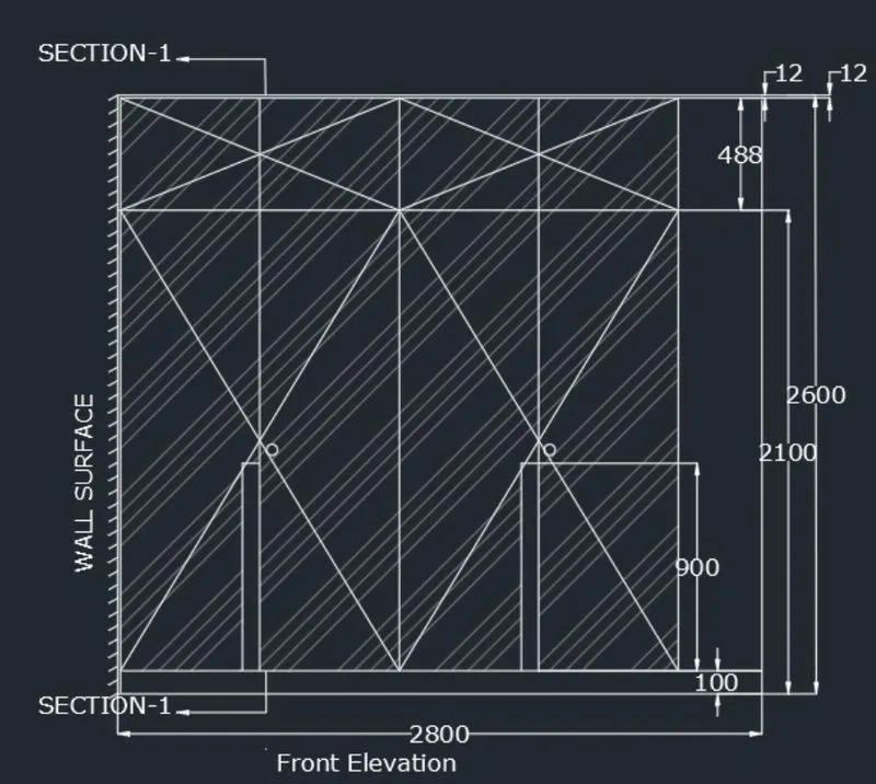
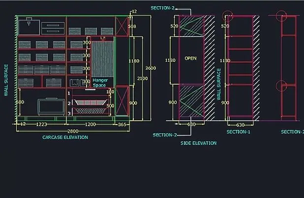
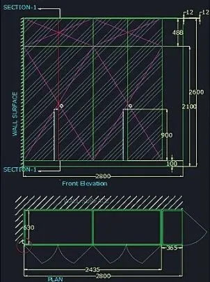
AIM: To draw the elevation and details of a wardrobe as shown in the Figure below. After sketching provide the dimensions and text with the use of layers. Using proper text styles and dimension methods to document it. Also, assuming dimensions, wherever needed.
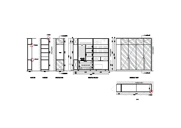
Procedure:
Step1:
Set units to mm
Limits and limit max are set
Zoom command is used
Step2:
Type REC in the command line, specify a point and enter length and width as 2800,2600
Type OFFSET in the command tab
Offset from top of dimensions 12 and 488 mm
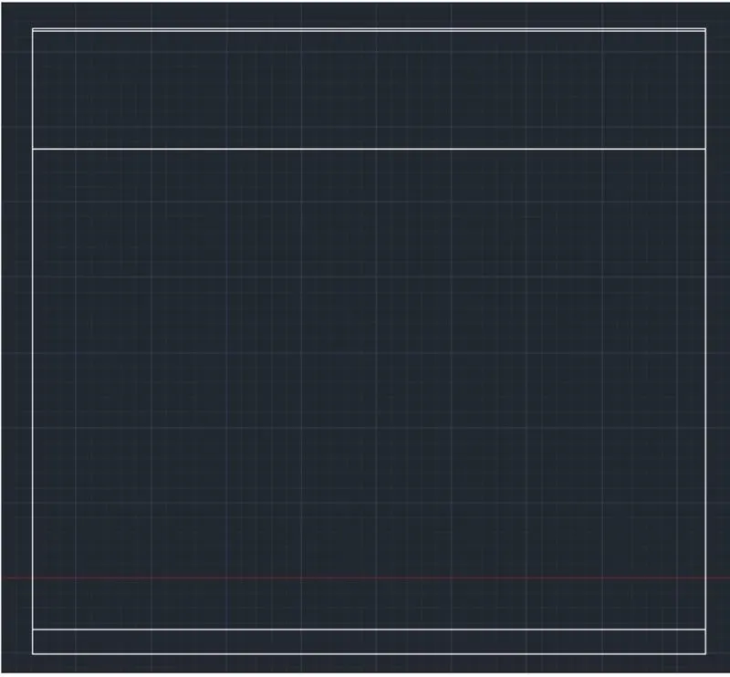
Step3:
In the command line type offset
Click from the side at the distance of 608.75 and 365
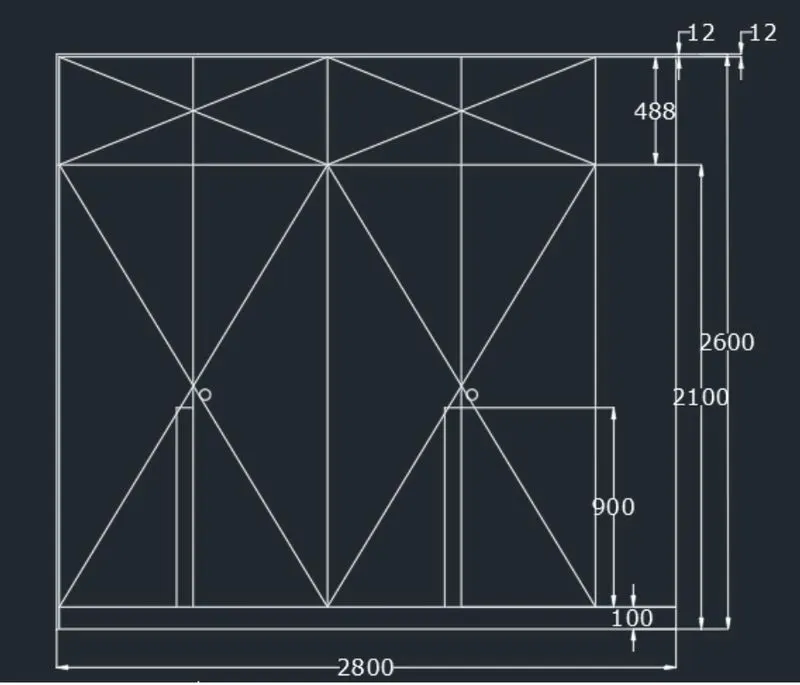
Step 4
Type L in the command prompt and increase the transparency to create wall surface
Hatch on a scale 30
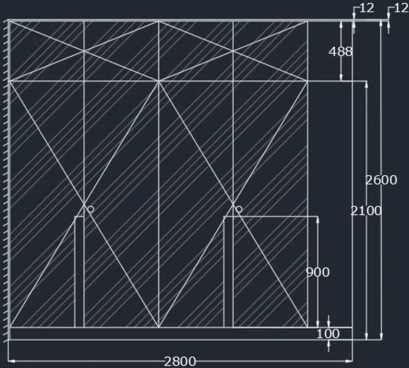
Step 5
Type DIMLIN and write the texts along as per requirement
Step 6:
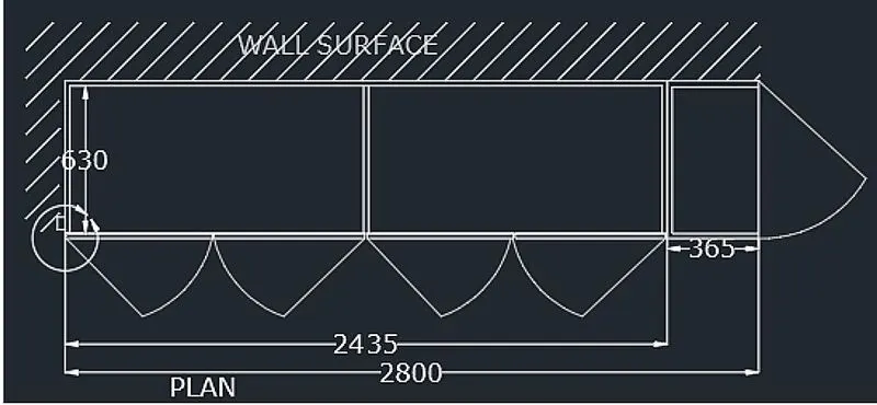
Type REC in the command tab and specifying the point specify 630,2800
Type DIMLIN and write the texts along as per requirement
Step 7:
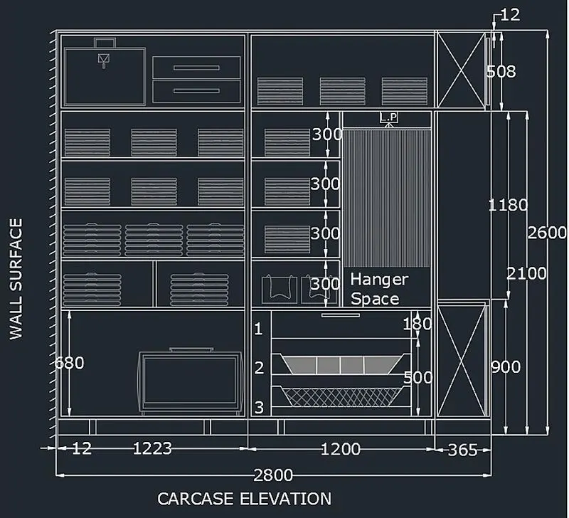
Type REC in the command line, specify a point and enter length and width as 2800,2600
With the help of line command make drawers and cabinets giving a specific colour grey
Type DIMLIN and write the texts along as per requirement
Step 8:
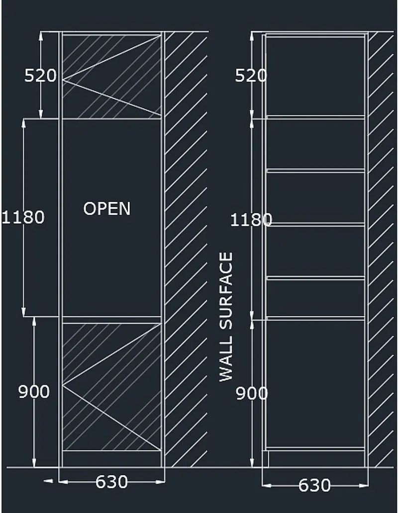
Type REC in the command line, specify a point and enter length and width as 520x630, 1180x630 , 900x630. Repeat 2x
Step 9:
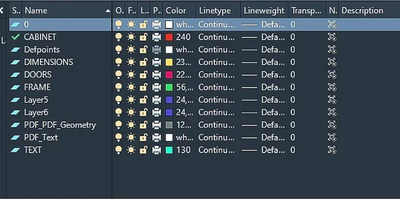
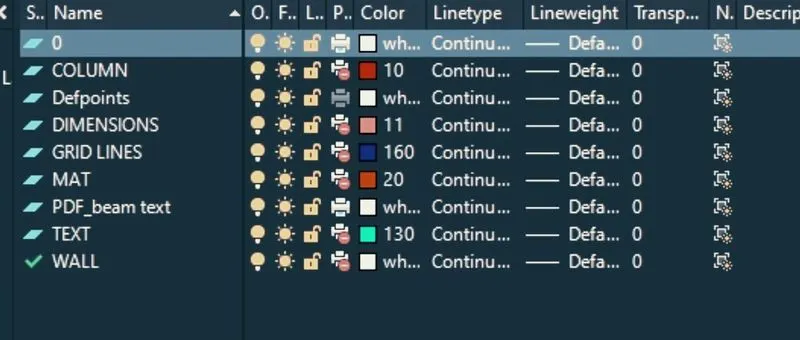
Place in drawing in respective layers as per choice
RESULT
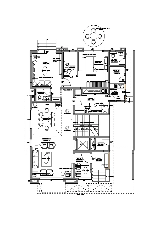
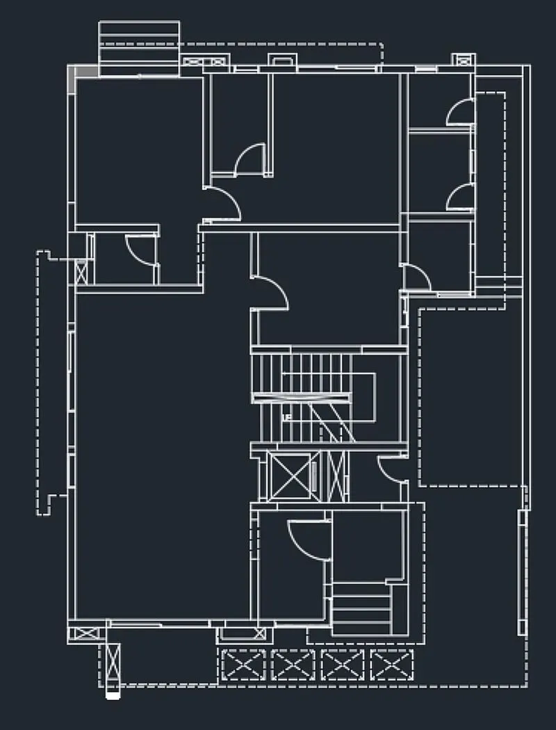
2. Draw the floor plan as shown in the Figure using the proper drafting tools to sketch the plan.
- Walls (Exterior and Interior)
Wall Thickness: Exterior Wall- 230mm, Interior Wall: 150 mm
- Doors and Windows: Assuming the size of the doors and window.
2.1 Stairs: Tread-300mm, Riser-150mm
- Insert Text wherever required
- Insert the dimensions using proper dimension techniques
Procedure:
Step1:
Set units to mm
Limits and limit max are set
Zoom command is used
Step2:
In the command tab type XLINE to draw the infinite lines
Type OFFSET to draw particular distances
Using circle coomand to create doors and triming the extra part
Step3:
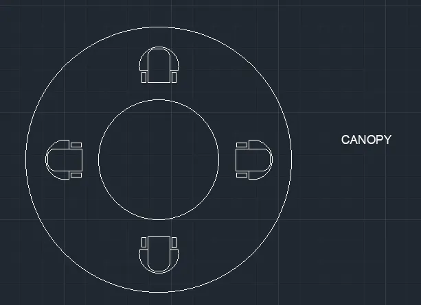
For Canopy
Make A circle taking radius 452 by typing circle in the command tab
Taking the same center draw another circle of radius 1398
For Seats
Type REC and draw a rectangle as 662.3,298
Type F for fillet and radius as 100 select the sides
Type ARC and use Continous arc
Create a offset at 30 and 60 and join the ends
Create the arm rest using rectangle
Now using polar array and selecting 4 items
Step4:
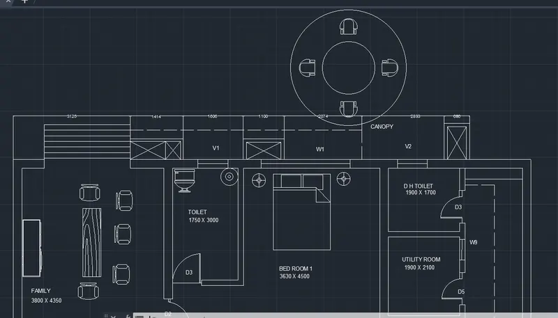
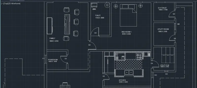
Type DIMLIN and write the texts along as per requirement
Using Text name the rooms
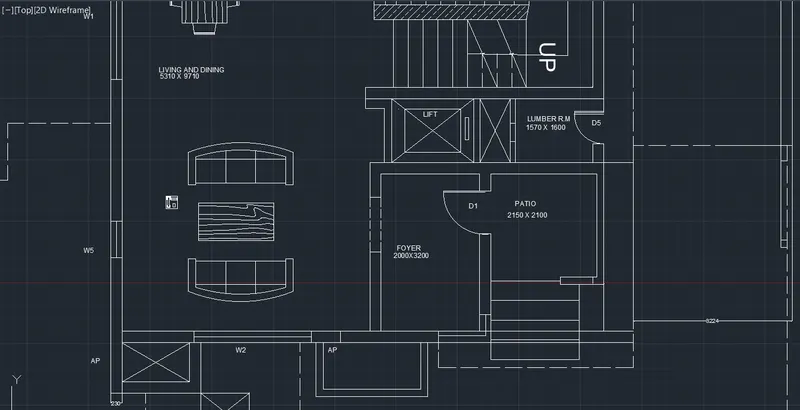
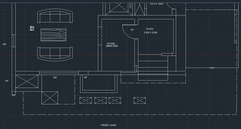
Step5:
Place in drawing in respective layers as per choice
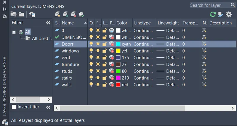
RESULT:
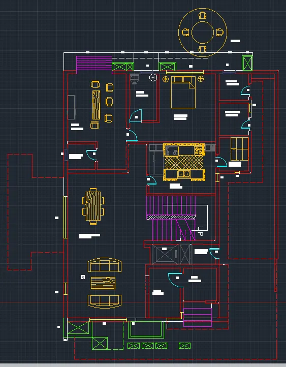
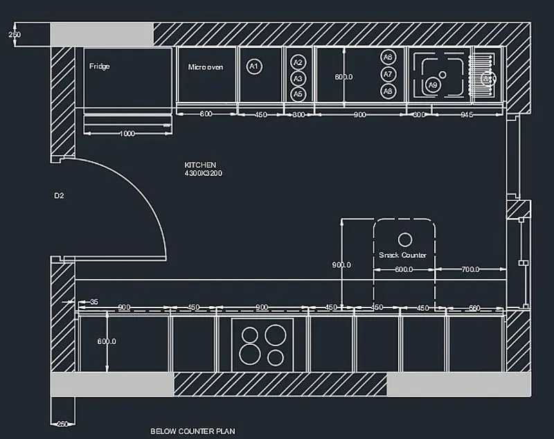
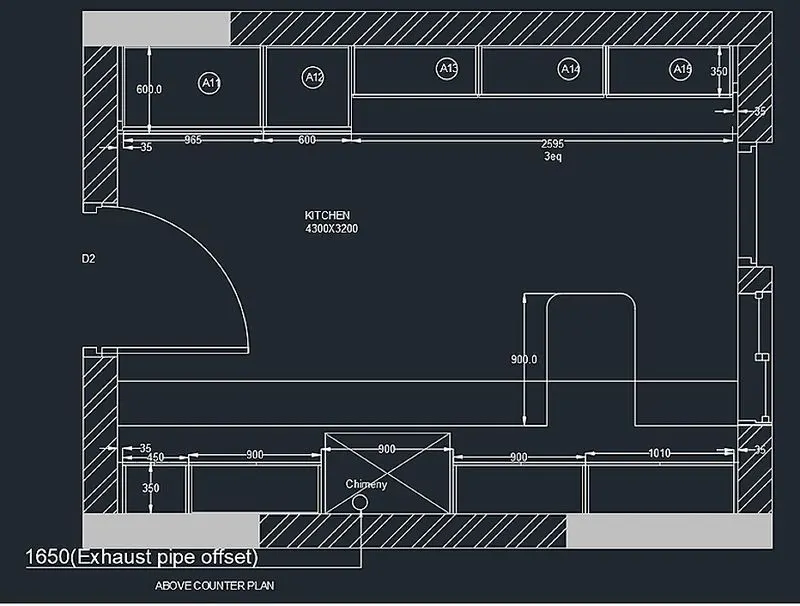
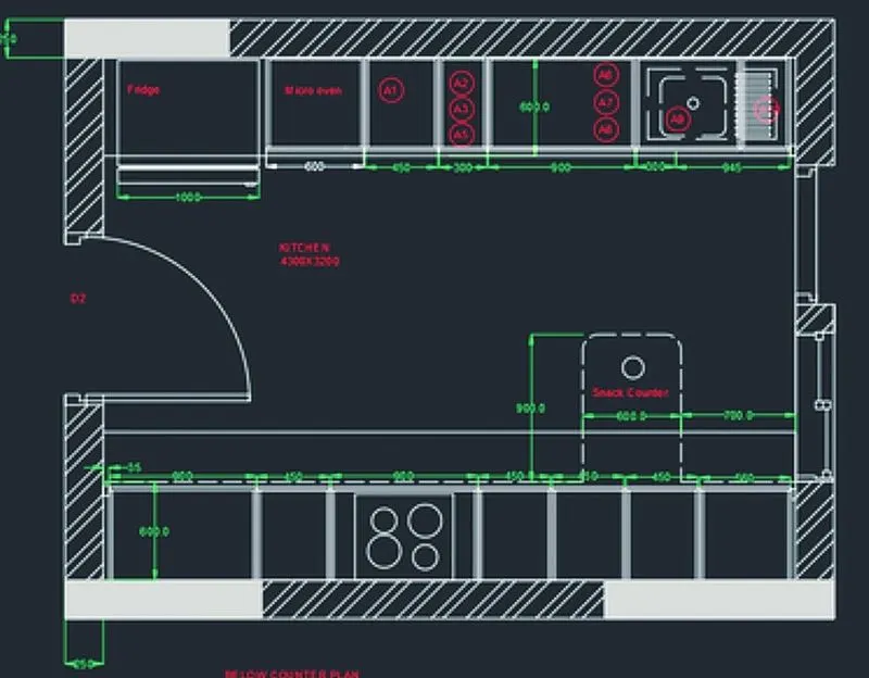
3. Create the Kitchen Layout as shown in the Figure below. Using proper dimension techniques to dimension the kitchen layout. Also, insert text wherever required. All dimensions are in mm.
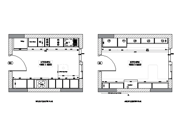
Procedure:
Step1:
Set units to mm
Limits and limit max are set
Zoom command is used
Step2:
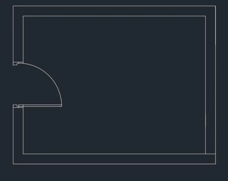
Type REC in the command line, specify a point and enter length and width as 4734x3688
Type OFFSET in the command tab
Offset it to a distance 250 mm

Use arc for creating doors
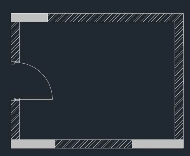
In the command tab type hatch and hatch as per drawing
Step3:
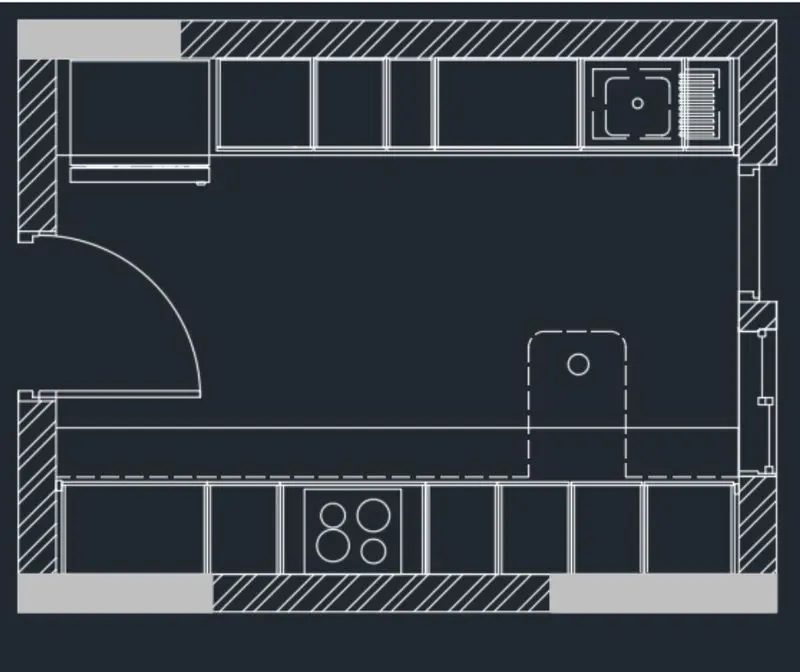
Type ADC
ADC>SAMPLE>DESIGN CENTER>KITCHEN.DWG
Right click and choose CREATE TOOLBAR
Choose the oven,fridge wet block from the options and place them as per drawing
In the line type choose dotted lines and select the scale 2 as per requirement
Step 4:
In the command tab type text and choose the justification,style,angle of the text
Dimension the drawing and use text as per needed
Step 5:
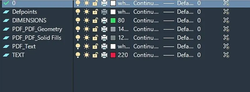
Place all the elements in the required layers as per choice
RESULT
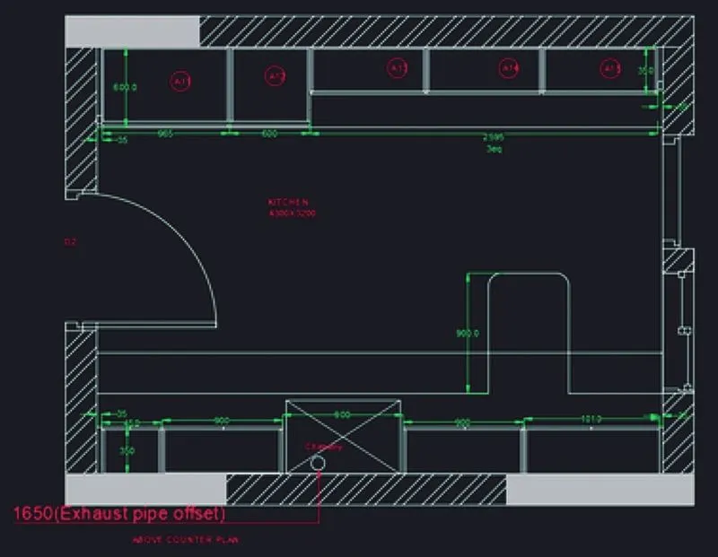
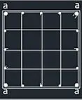
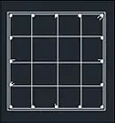
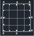
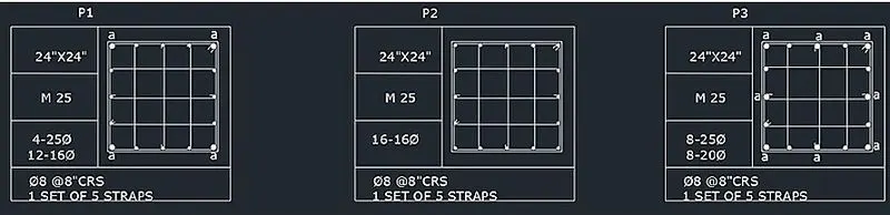
4. Sketch the column details as shown in Figure. Insert dimensions and text in the figure. Referring to the bar sizes from the schedule.
8mm ---- 0.31 Inches
25mm--- 1 inches
16mm—0.62 inches
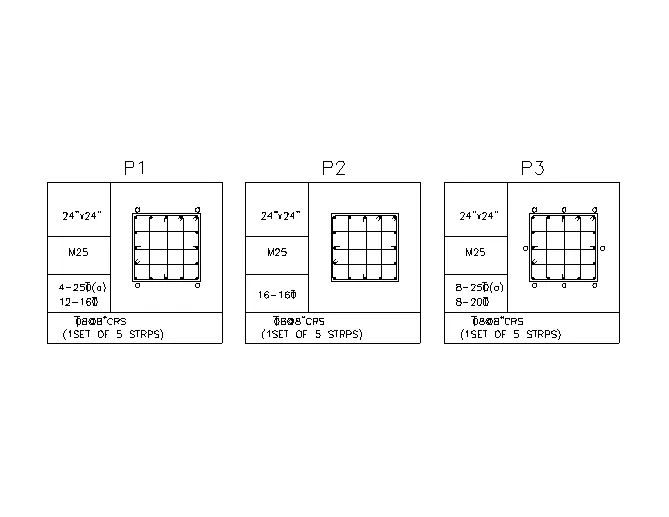
Procedure:
Step1:
Set units to mm
Limits and limit max are set
Zoom command is used
Step2:
Type REC in the command line, specify a point and enter length and width
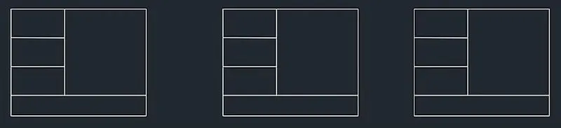
Step3:
Use the text command and choose the justification,style,angle of the text
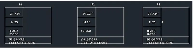
Step4:
In the command tab type lines to draw the bars
Type circle to draw reinforcement
P1
P2
P3
Step 5:
Scale the colums into the tables
RESULT
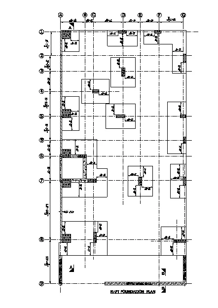
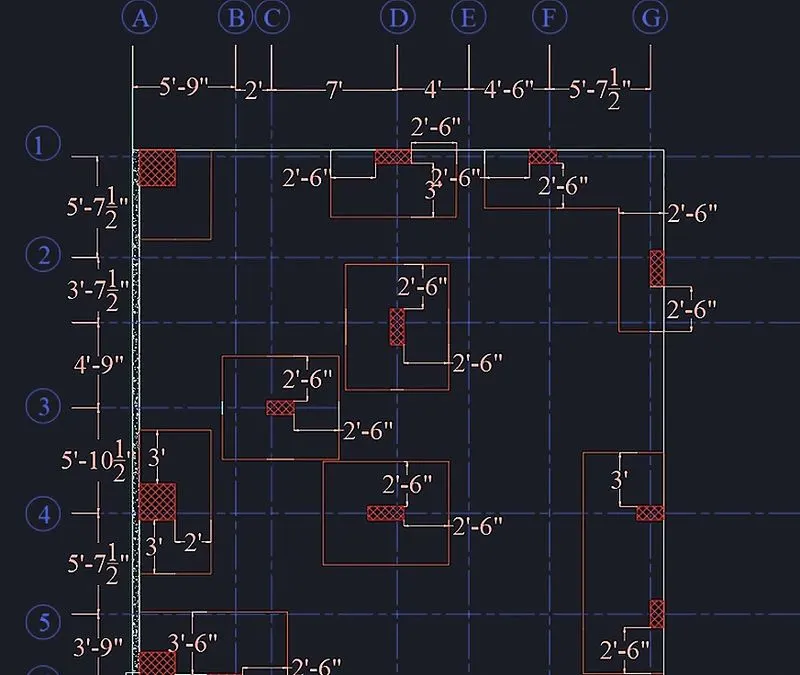
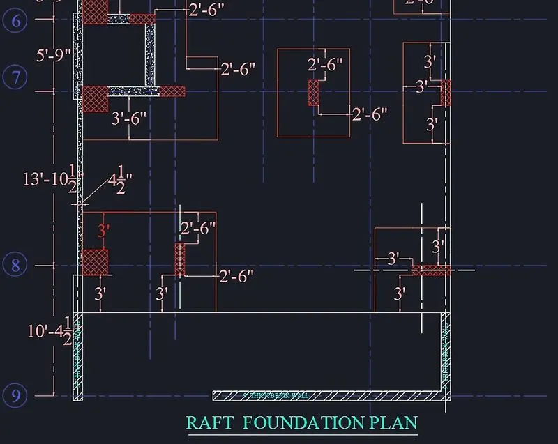
Draw the Raft Layout as shown in the Figure. Assume the column size as per your knowledge. You can take the sizes as: 24”x24”, 9” x 24”, 9” x 18”, and 9’ x 24”. You can import the raft_foundation.pdf to ensure the missing dimensions.
Procedure:
Step1:
Set units to Architecture>Inches
Limits and limit max are set
Zoom command is used
Step2:
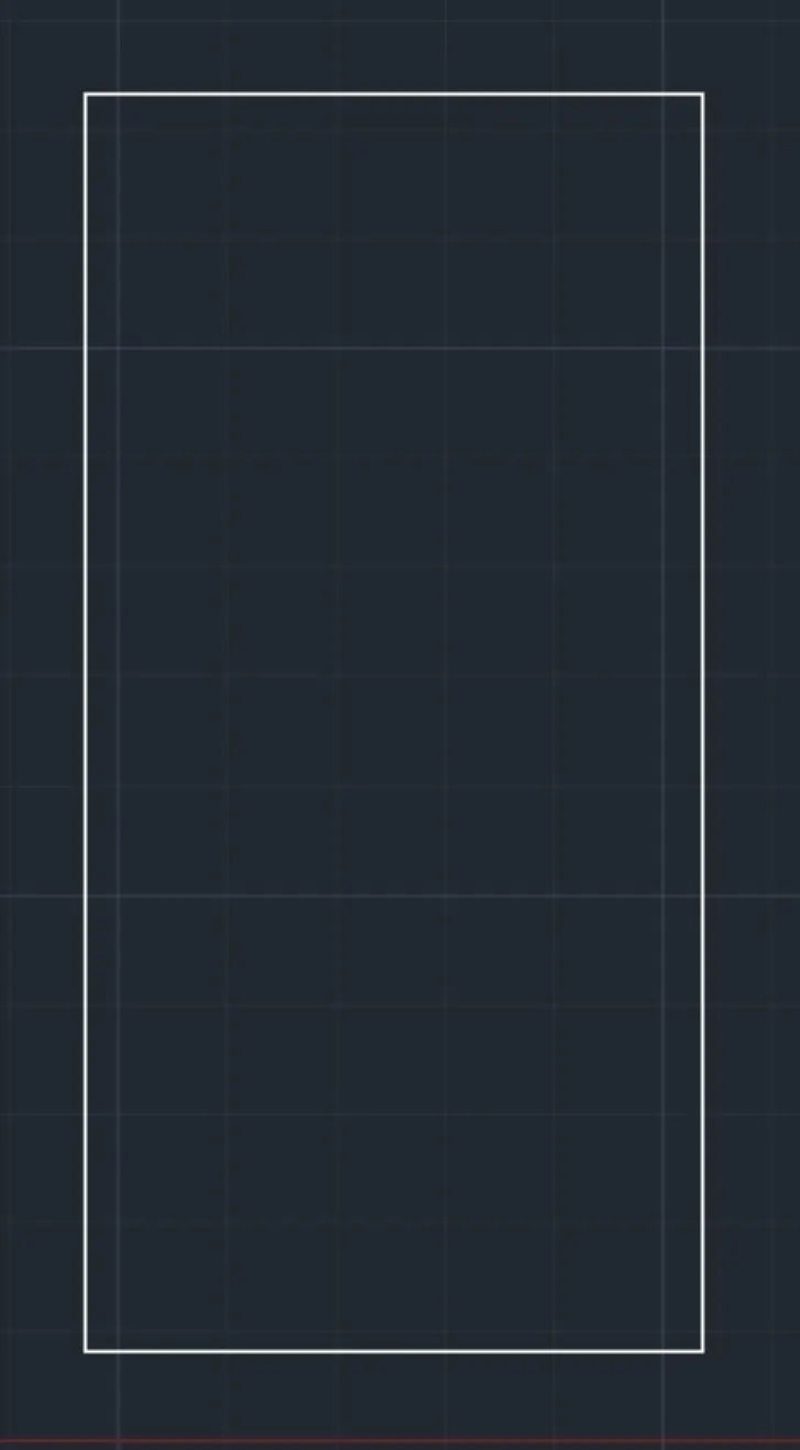
Type REC in the command line, specify a point and enter length and width> 29'-7"x 60'
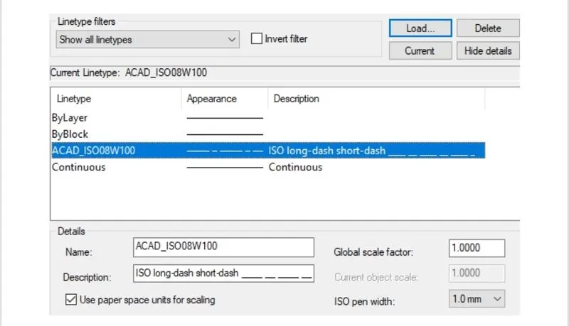
Select the line type and choose ISO long dot short dot
Set current
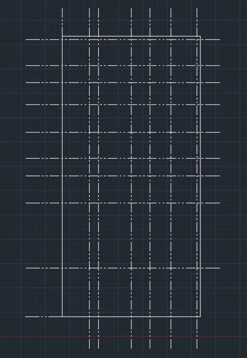
With the help of dotted lines and offset 4 1/2" command the grids are drawn as per drawing
Step3: In the command tab type offset of distance 4"
RIBBON>HATCH>AR-CONC
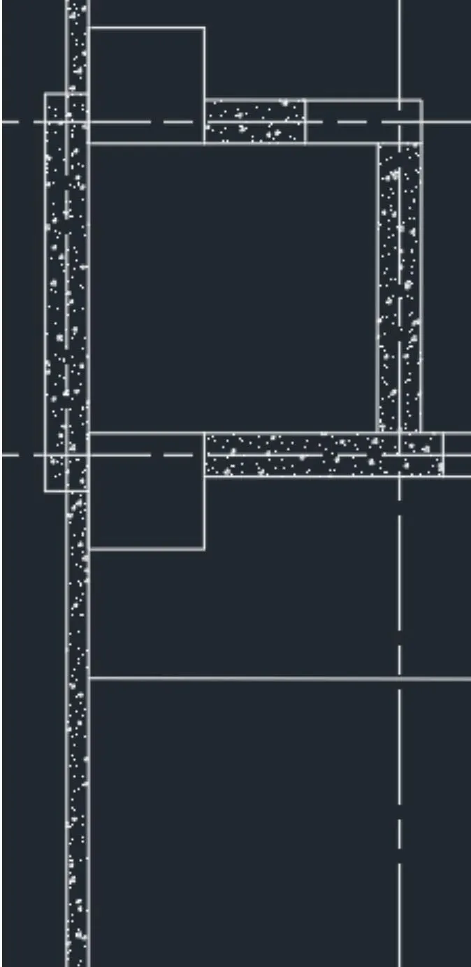
In the command prompt type REC with dimensions 2'x2'
In the command tab type REC to draw the colums as per drawing
In the ribbon choose hatch and select ANS137 hatch the specific columns
In the ribbon choose hatch and select ANS138 hatch the specific walls
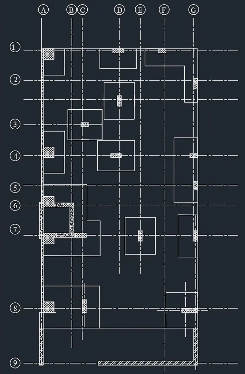
Step4:
In the ribbon tab type annotate then text
Text to write the given annotations
In the ribbon tab select dimensions to give the dimensions
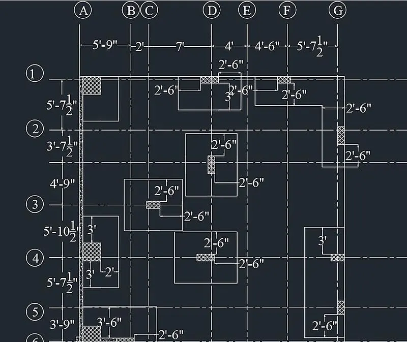
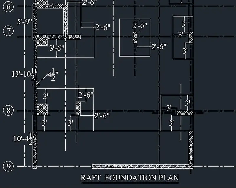
Step 5:
Place all the elements in the required layers as per choice
RESULT
CONCLUSION:
Result of every drawing step by step is shown in pictures attached.