Creating a Wardrobe detailed drawing, Floor Plan, Kitchen Layout and Column Detail using AutoCad
1. AIM
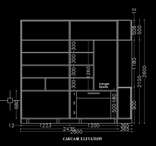
Draw the elevation and details of a wardrobe as shown in the Figure below. After sketching, you need to provide the dimensions and text with the use of layers. Use proper text styles and dimension methods to document it. Also, assume dimensions, wherever needed.
Note: All dimensions are in mm.
PROCEDURE
Set the unit using the UNIT command to decimal.
To create the carcase elevation, draw the vertical line using the LINE command equal to 2600 units.
Using the OFFSET command create offset at a distance of 365 units, 1200 units, 1223 units, and 12 units.
Close the figure using the LINE command.
Draw the boundaries around all the lines by using the OFFSET command equal to 20 units.
By using the FILLET command, fillet the internal boundaries.
For creating the partitions, offset the horizontal lines at the distance of 12 units, 508 units, 1180 units, and 900 units using the OFFSET command.
Using the TRIM command, clear the “hanger space”.
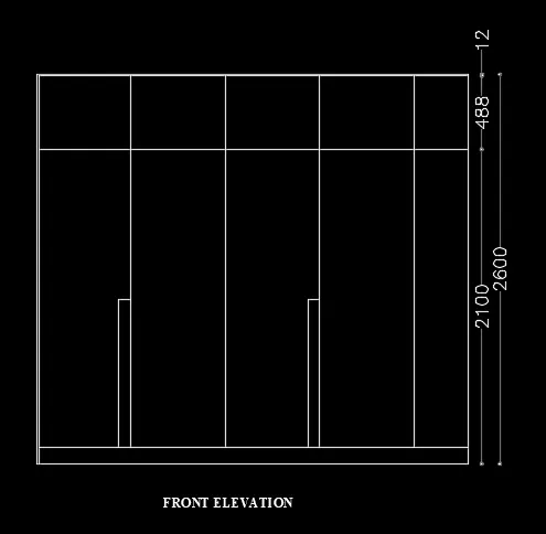
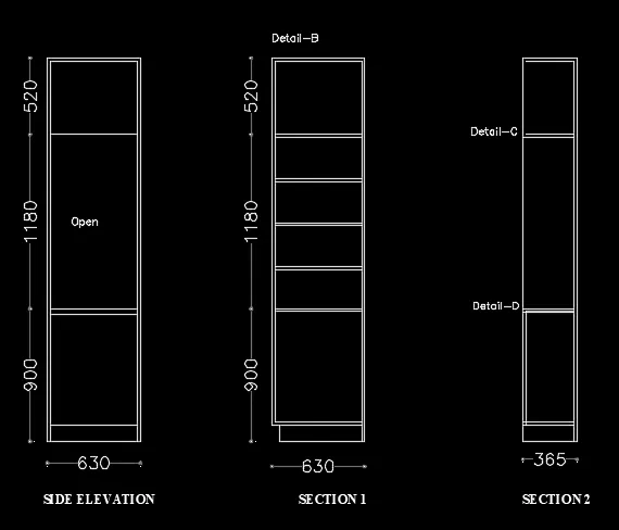
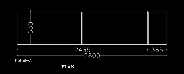
To create the front elevation, draw the vertical line using the LINE command equal to 2600 units.
Using the OFFSET command create offset at a distance of 365 units, 630 units, 630 units, and 630 units.
Close the figure using the LINE command.
Draw the boundaries around all the lines by using the OFFSET command equal to 20 units.
By using the FILLET command, fillet the internal boundaries.
OFFSET the horizontal line by 12 units, 488 units, and 2100 units.
OFFSET the bottom line by 100 units.
For creating the side elevation, draw the vertical line using the LINE command equal to 2600 units.
Using the OFFSET command create an offset at a distance of 630 units.
Close the figure using the LINE command.
Draw the boundaries around all the lines by using the OFFSET command equal to 20 units.
By using the FILLET command, fillet the internal boundaries.
OFFSET the horizontal line by 520 units, 1180 units, and 900 units.
For creating the section 1, draw the vertical line using the LINE command equal to 2600 units.
Using the OFFSET command creates an offset at a distance of 630 units.
Close the figure using the LINE command.
Draw the boundaries around all the lines by using the OFFSET command equal to 20 units.
By using the FILLET command, fillet the internal boundaries.
OFFSET the horizontal line by 520 units, 1180 units, and 900 units.
Divide the 1180 unit part into 4 sections by using the DIVIDE command.
Draw the outer boundary of 20 units using the LINE and OFFSET commands.
For creating the section 2, draw the vertical line using the LINE command equal to 2600 units.
Using the OFFSET command creates an offset at a distance of 365 units.
Close the figure using the LINE command.
Draw the boundaries around all the lines by using the OFFSET command equal to 20 units.
By using the FILLET command, fillet the internal boundaries.
OFFSET the horizontal line by 500 units, 1160 units, and 900 units.
Draw the boundaries around all the lines by using the OFFSET command equal to 20 units.
By using the FILLET command, fillet the internal boundaries.
Draw the outer boundary of 20 units using the LINE and OFFSET commands.
Using the MTEXT command, type in the names and details of the created figures for texts.
In layer properties, create two “new layers”.
Name it as “DIMENSION” and “TEXT”
Assign 0.05mm line weight to both the layers.
Enter DIMENSION LINEAR command: DIMLIN
Specify first extension line origin:
Specify second extension line origin:
Left-click to exit the command.
Mention all the dimensions of the created figures
Select all the texts and transfer them to the TEXT layer.
Select all the dimension lines and transfer them to the DIMENSION layer.
RESULT
2. AIM
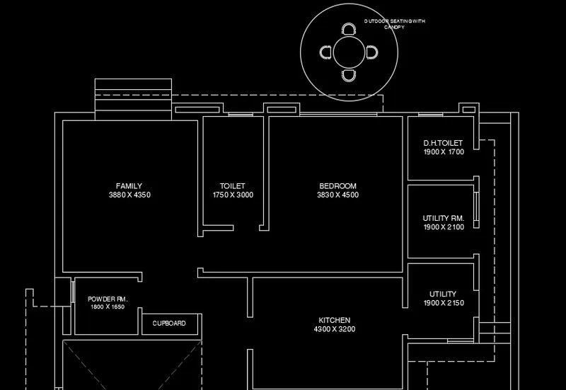
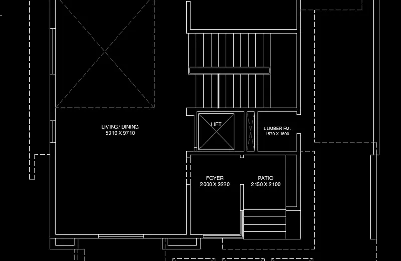
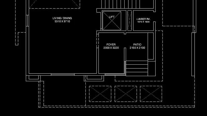
Draw the floor plan as shown in the Figure. Use the proper drafting tools to sketch the plan. Do not hatch or draw the furniture. You need to draw the floor plan with the following:
Note: You can also import the Floor_Plan.pdf into your current drawing and start working on the project. You need to scale the imported pdf file using reference option. All dimensions are in mm.
- Walls (Exterior and Interior)
Wall Thickness: Exterior Wall- 230mm, Interior Wall: 150 mm (Wherever Required)
- Doors and Windows: Assume the size of the doors and window.
2.1 Stairs: Tread-300mm, Riser-150mm
- Insert Text wherever required
- Insert the dimensions using proper dimension techniques
PROCEDURE
Set the unit using the UNIT command to decimal.
Using the LINE command to create a line of 3800 units and a line of 4350 units perpendicular to it.
OFFSET the exterior wall by 230 units, and interior walls by 150 units.
OFFSET 1750 units for the toilet.
OFFSET 150 unit for the internal wall.
OFFSET 3830 units for bedroom.
OFFSET 150 unit for the internal wall.
OFFSET 1900 units for utility.
OFFSET 150 unit for the internal wall.
OFFSET 4300 unit for kitchen.
OFFSET 150 unit for the internal wall.
OFFSET 3040 unit for the staircase.
OFFSET 150 unit for the internal wall.
OFFSET 1600 unit for LUMBER ROOM AND LIFT.
OFFSET 2100 unit for patio.
Using TRIM command, to create opening of doors and windows
TRIM 1070 units for D1 opening
TRIM 960 units for D2 opening
TRIM 760 units for D3, D4, and D5 opening
TRIM 1880 units for W1, W2 opening
TRIM 900 units for W5, W9 opening
TRIM 700 units for V1, V2 opening
Enter DIMENSION LINEAR command: DIMLIN
Specify first extension line origin:
Specify second extension line origin:
Left-click to exit the command.
Mention all the dimensions of the created plan
Enter TEXT command: MTEXT
Specify first corner: click to type the name of the rooms and respective dimensions
Type the name of rooms and their dimensions
To create outdoor seating with canopy
Enter CIRCLE command: C
CIRCLE Specify center point for circle: click on the points
Specify radius of circle or[Diameter]: 1398
Enter CIRCLE command: C
CIRCLE Specify center point for circle: click on the same point
Specify radius of circle or[Diameter]: 452
Enter LINE command: L
LINE specify first point: click left mouse button, drag the mouse right and type 200
Specify next point or [Undo]: drag the mouse up and type 100
Create the second vertical line
Enter FILLET command: F
FILLET select first object or [Undo Polyline Radius Trim Multiple]: R
Specify fillet radius: 150
Select first object: select vertical side
Select second object: select other vertical side
Enter ARRAY command: AR
ARRAY select objects: select the created chair
Enter array type [Rectangular Path Polar]: PO
Specify centre point of array: click the centre of the circle
Select grip to edit array [Associative Base point Items Angle]: I
Enter number of item in array: 4
Exit command
RESULT
3. AIM
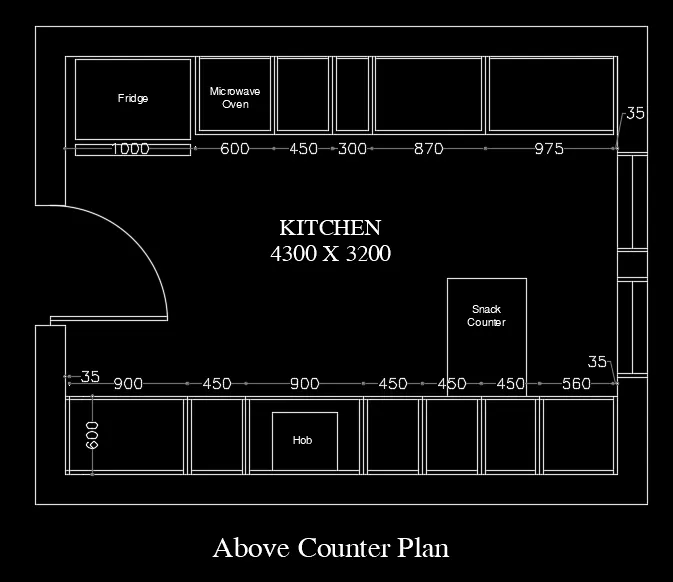
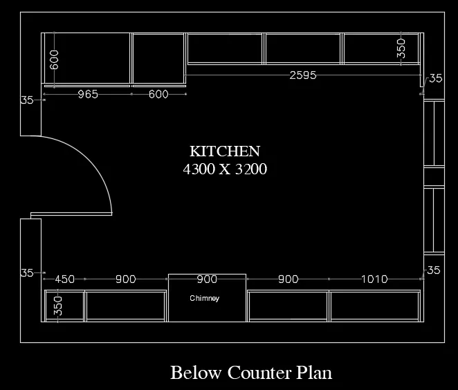
Create the Kitchen Layout as shown in the Figure below. Also, use proper dimension techniques to dimension the kitchen layout. Also, insert text wherever required. All dimensions are in mm.
PROCEDURE
Set the unit using the UNIT command to decimal.
Using the LINE command to create a line of 4300 units and a line of 3200 units perpendicular to it.
OFFSET the kitchen slab by 600 units.
Draw the boundaries around all the lines by using the OFFSET command equal to 20 units.
By using the FILLET command, fillet the internal boundaries.
For creating the partitions, offset the horizontal lines at the distance of 35 units, 900 units, 450 units, 900 units, 450 units, 450 units, 450 units, 560 units, and 35 units using the OFFSET command.
Draw the boundaries around all the lines by using the OFFSET command equal to 20 units.
Using TRIM command, trim the extending lines.
OFFSET the kitchen slab by 600 units.
Draw the boundaries around all the lines by using the OFFSET command equal to 20 units.
By using the FILLET command, fillet the internal boundaries.
For creating the partitions, offset the horizontal lines at the distance of 1000 units, 600 units, 450 units, 300 units, 900 units, 945 units, and 35 units using the OFFSET command.
Draw the boundaries around all the lines by using the OFFSET command equal to 20 units.
Using TRIM command, trim the extending lines.
Using RECTANGLE command, create the fridge.
Specify dimension of rectangle as 800 X 620
Enter TEXT command: MTEXT
Specify first corner: click to type the name of appliances.
Type the name of appliances
Enter DIMENSION LINEAR command: DIMLIN
Specify first extension line origin:
Specify second extension line origin:
Left-click to exit the command.
Mention all the dimensions of the created footings
Using TRIM command, trim the door opening of 920 units.
TRIM the window openings on opposite side of 760 units.
Enter COPY command: CP
COPY select the objects to copy: Select the entire kitchen
Copy to create above counter plan.
OFFSET the kitchen slab by 600 units.
Draw the boundaries around all the lines by using the OFFSET command equal to 20 units.
By using the FILLET command, fillet the internal boundaries.
For creating the partitions, offset the horizontal lines at the distance of 35 units, 965units, 600 units using the OFFSET command.
Draw the boundaries around all the lines by using the OFFSET command equal to 20 units.
Using TRIM command, trim the extending lines.
OFFSET the kitchen slab by 350 units.
Enter DIVIDE command: DIV
Select the object to divide:
Enter number of segments: 3
Draw the partition using LIN command.
Draw the boundaries around all the lines by using the OFFSET command equal to 20 units.
Using TRIM command, trim the extending lines.
OFFSET the kitchen slab by 350 units.
Draw the boundaries around all the lines by using the OFFSET command equal to 20 units.
By using the FILLET command, fillet the internal boundaries.
For creating the partitions, offset the horizontal lines at the distance of 35 units, 450 units, 900 units, 900 units, 900 units, 1010 units, and 35 units using the OFFSET command.
Draw the boundaries around all the lines by using the OFFSET command equal to 20 units.
Using TRIM command, trim the extending lines.
Enter DIMENSION LINEAR command: DIMLIN
Specify first extension line origin:
Specify second extension line origin:
Left-click to exit the command.
Mention all the dimensions of the created partitions.
RESULT
4. AIM
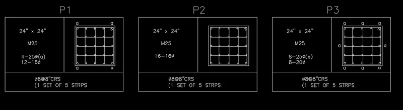
Sketch the column details as shown in Figure. Insert dimensions and text in the figure. Refer to the bar sizes from the schedule.
8mm ---- 0.31 Inches
25mm--- 1 inches
16mm—0.62 inches
PROCEDURE
Set the unit using the UNIT command to architectural
Enter LINE command: L
Specify first point:
Create a 24” x 24” column
Enter OFFSET command: O
OFFSET 1” inside the column
Enter CIRCLE command: C
Create Circle with diaeter 1” and 0.62” and arrange as shown in schedule
Enter MTEXT:
Type the schedule detailing
Enter LINE command:
Create a table around the column schedule.
Enter COPY command: CP
Select the whole drawing ad copy twice
Enter TEXTEDIT command:
Edit the schedule as per the figure.
RESULT
5. AIM
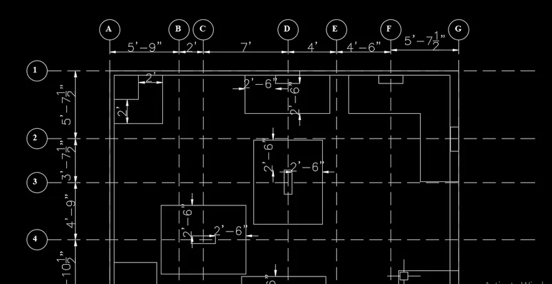
Draw the Raft Layout as shown in the Figure. Assume the column size as per your knowledge. You can take the sizes as: 24”x24”, 9” x 24”, 9” x 18”, and 9’ x 24”. You can import the raft_foundation.pdf to ensure the missing dimensions.
PROCEDURE
Set the unit using the UNIT command to architectural.
Change the line type to “HIDDEN2”.
Create gridline A using the LINE command of 65’.
OFFSET 5’9” for gridline B.
OFFSET 2’ for gridline C.
OFFSET 7’ for gridline D.
OFFSET 4’ for gridline E.
OFFSET 4’6” for gridline F.
OFFSET 5’7.5” for gridline G.
Create the horizontal gridline 1, exceeding a little from gridline A and gridline G
OFFSET 5’7.5” for gridline 2.
OFFSET 3’7.5” for gridline 3.
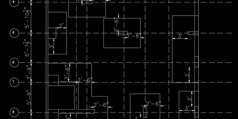
OFFSET 4’9” for gridline 4.
OFFSET 5’10.5” for gridline 5.
OFFSET 5’7.5” for gridline 5’.
OFFSET 3’9” for gridline 6.
OFFSET 5’9” for gridline 7.
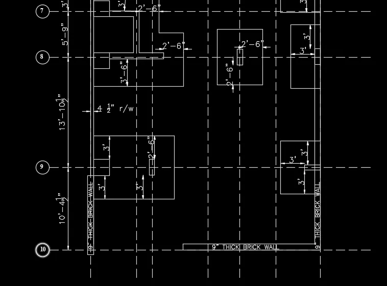
OFFSET 13’10.5” for gridline 8.
OFFSET 10’4.5” for gridline 9.
At A1, create 24” X 24” column.
Using OFFSET command with distance 2’6”, create foundation.
At D1, create 9” X 24” column.
Using OFFSET command with distance 2’6”, create foundation.
At F1, create 9” X 24” column.
Using OFFSET command with distance 2’6”, create foundation.
At G2, create 24” X 9” column.
Using OFFSET command with distance 2’6”, create foundation.
At D3, create 24” X 9” column.
Using OFFSET command with distance 2’6”, create foundation.
At C4, create 9” X 24” column.
Using OFFSET command with distance 2’6”, create foundation.
At A5, create 24” X 24” column.
Using OFFSET command with distance 2’ vertical and 3’ horizontal create foundation.
At D5, create 9” X 24” column.
Using OFFSET command with distance 2’6”, create foundation.
At G5, create 9” X 24” column, at G6 create 24” X 9” column.
Using OFFSET command with distance 3’, create combined foundation
At A7 and A8, create 24” X 24” column.
Using OFFSET command with distance 3’ create foundation.
At E8, create 9” X 24” column.
Using OFFSET command with distance 2’6”, create foundation.
At G8, create 9” X 24” column.
Using OFFSET command with distance 3’, create foundation.
At A9, create 24” X 24” column and at C9, create 24” X 9” column
Using OFFSET command with distance 3’ create foundation.
At C9, create 24” X 9” column
Using OFFSET command with distance 3’ create foundation.
Enter DIMENSION LINEAR command: DIMLIN
Specify first extension line origin:
Specify second extension line origin:
Left-click to exit the command.
Mention all the dimensions of the created footings
Using the MTEXT command, type in the names and details of the created figures for texts.
RESULT