Creating a Wardrobe detailed drawing, Floor Plan, Kitchen Layout and Column Detail using AutoCad
Question-1:
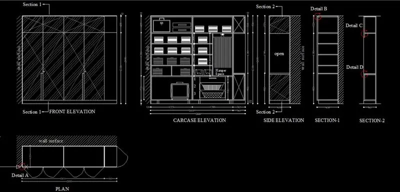
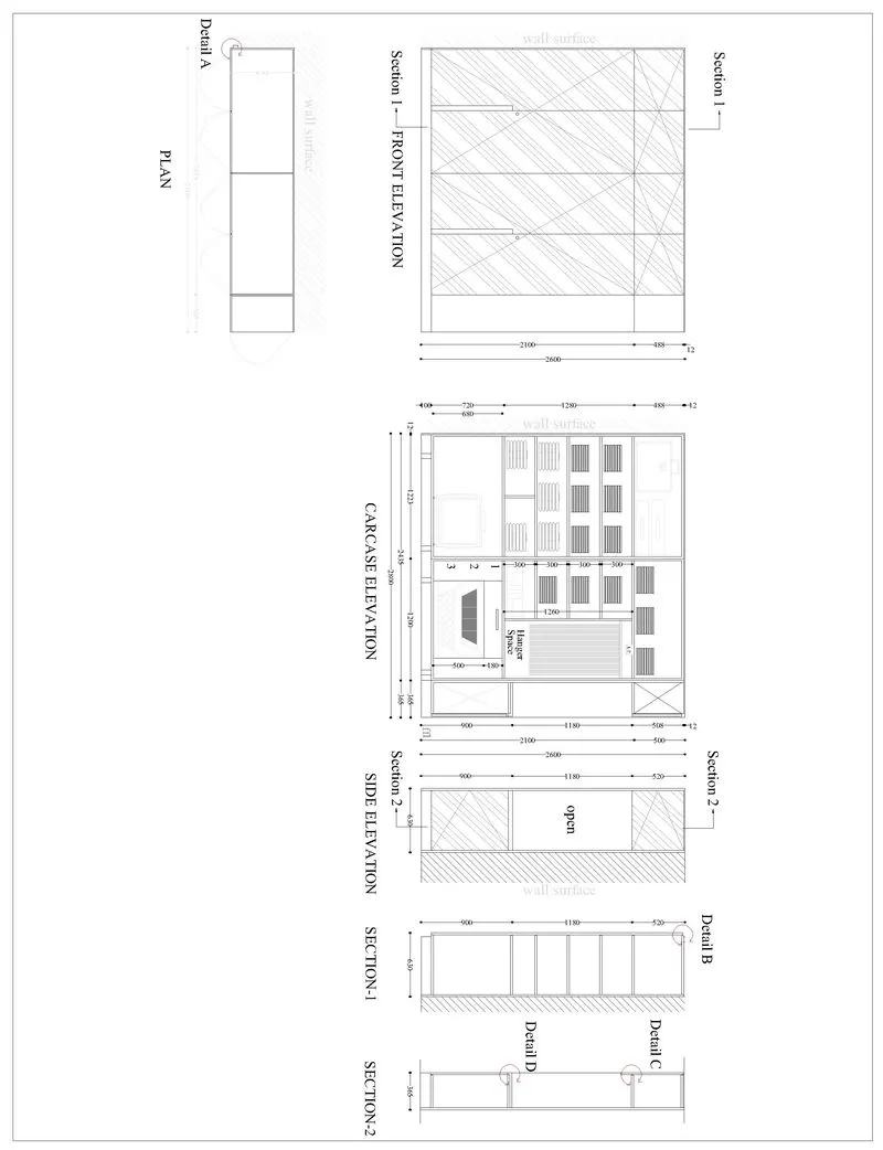
Aim: To draw the elevation and details of a wardrobe from given picture.
Introduction:
XLine: It means construction line. It has infinty edges we used for making wall. By typing "XL" on command line we envoke this tool.
Line: It connects one point to another points. Used to draft various elements.
Trim: This modification tool helps to cut extended edges on the drawing. And to trim inbetween two line or elements. "TR" command to envoke this tool.
Extend: It is also a modification tool, if we have some broken edges or need to extend some portion towards anonther element. "EX" command to envoke the tool.
Offset: Offset the existing element with certain distance. this tool avoid to create new parallel elements.
Layer: Each and every elements has unique property and unique style. This layer tool helps to organize those. Line weight, line style, colour gradient, freeze, lock. it has numerous benefits in Auto CAD drafting.
Hatch: Hatching helps to fill the voids with certain texture on it. If we draft wall means, we mention the brickwork details with the help of hatching.
Circle: Used to make circle elements in the sheet. Type "C" to envoke this tool. Here it is used to draft door.
Procedure:
step-1: Type "UN" to set the units of the drawing sheet.
step-2: Type "LIMITS" to set the sheet upper and lowest corner of the sheet.
step-3: Type"L" line to create plan for the wardrobe.
step-4: Type"O" to envoke the offset tool and to plot required dimensions.

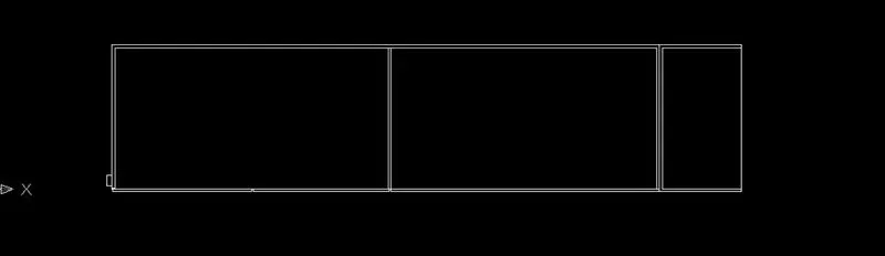
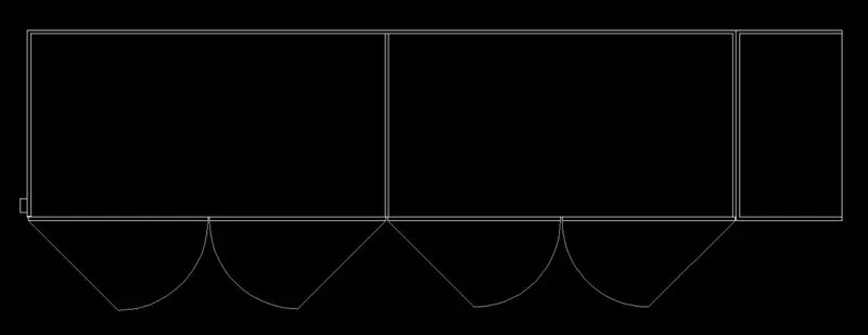
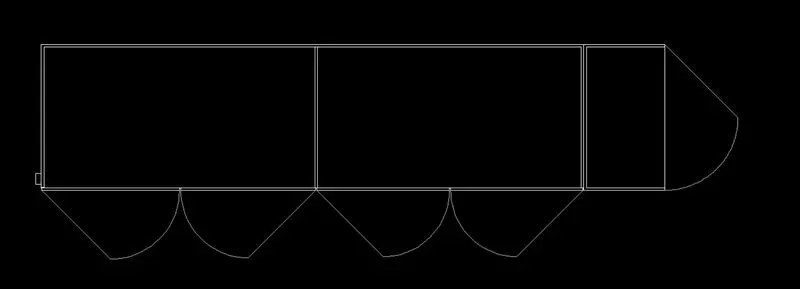
step-5: Type "C" circle to plot door portion of the plan.
step-6: Type "L" to connect circle with the angle of 315 degree.
step-7: Type "TR" to trim extended portion of the drawing.
step-8: Type"DIMLIN" to mark all dimensions in the sheet.
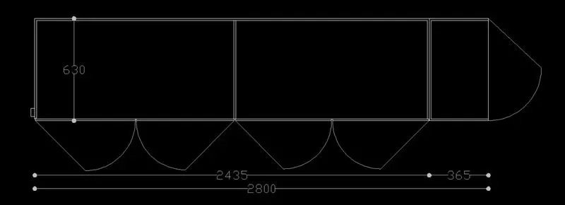
step-9: Type "H" to Hatch dialogue box and to select the surface we required to fill.
step-10: Press enter to plot hatch wall surface.

Step-11: Type "A" Arc command to mark detail A in the wardrobe plan.
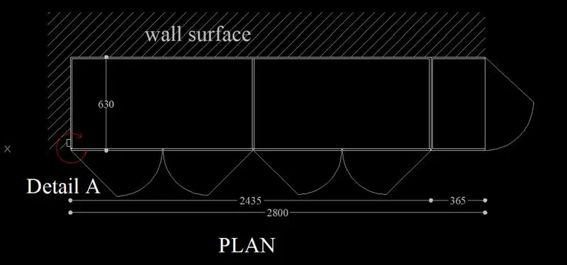
step-12: Type "O" offset to start draft elevation drawing of wardrobe with respect to plan.
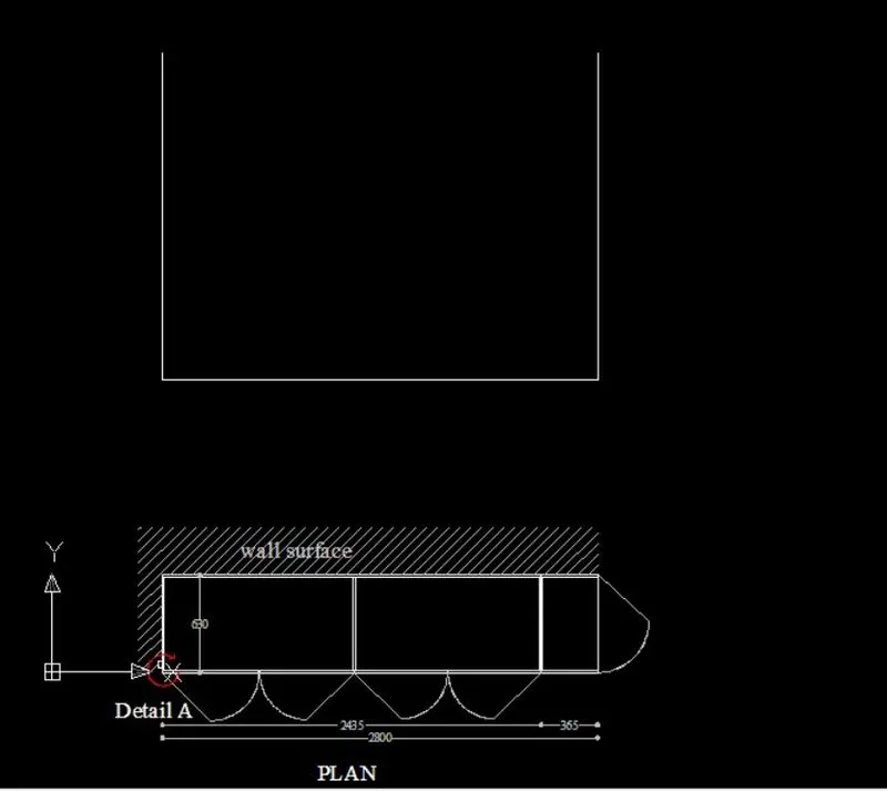
step-13: Type "O" to envoke offset tool and offsetting the existing line with required distance.
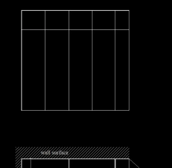
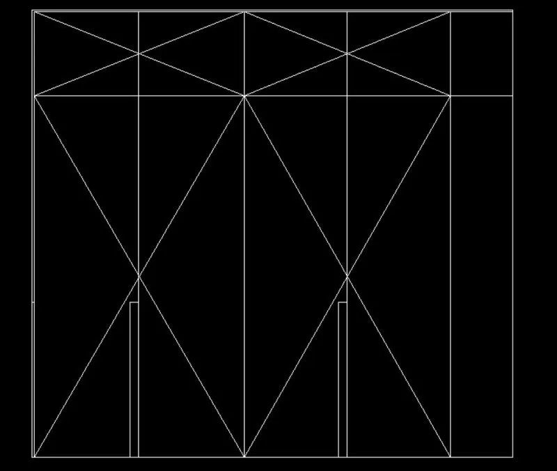
step-14: Type "L" line command to hatch the elevation surface.
step-15: Type "TR" trim to extended edges from drawing.
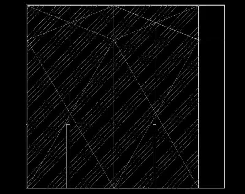
step-16: Type "H" to open hatch dialogue box to hatch wall surface on the elevation.
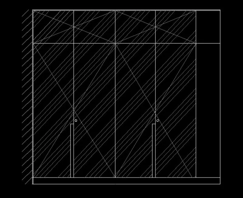
step-17: Type "DIMLIN" to mark all the dimensions on the drawing.
step-18: Type "LEADER" to mark specified notes on the diagram.
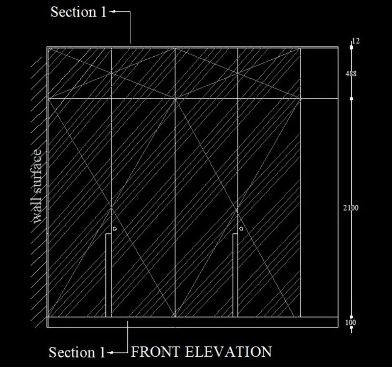
step-19: Type "O" offsetting the line to draft next section.
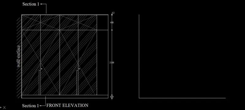
step-20: Type "O" offset the specified distance to plot section drawing.
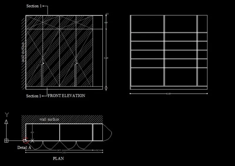
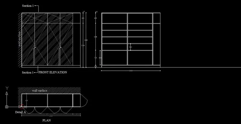
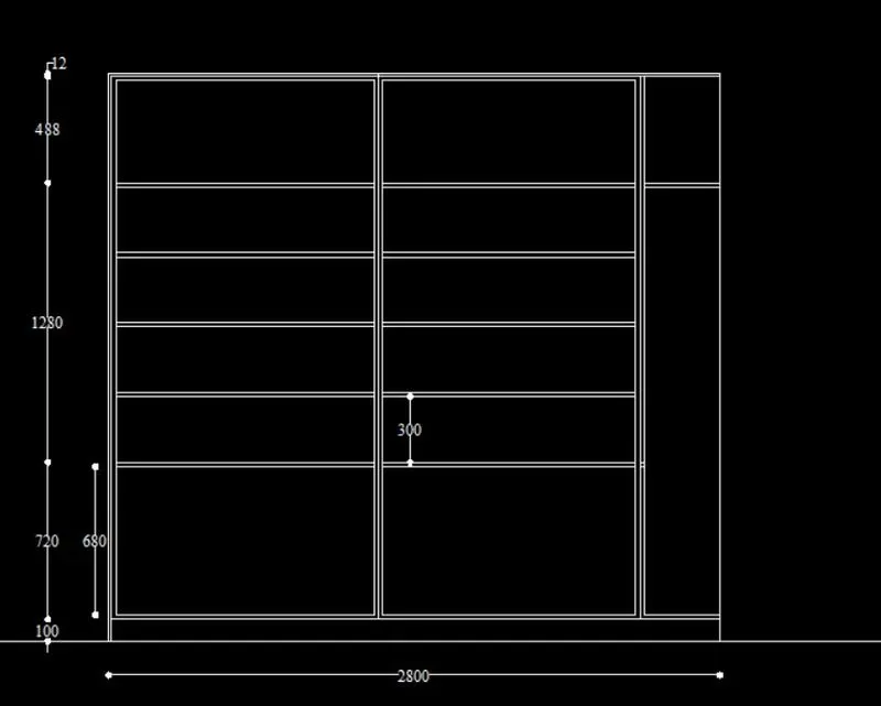
step-21: Type "DIMLIN" to mark all linear dimensions on the sheet.
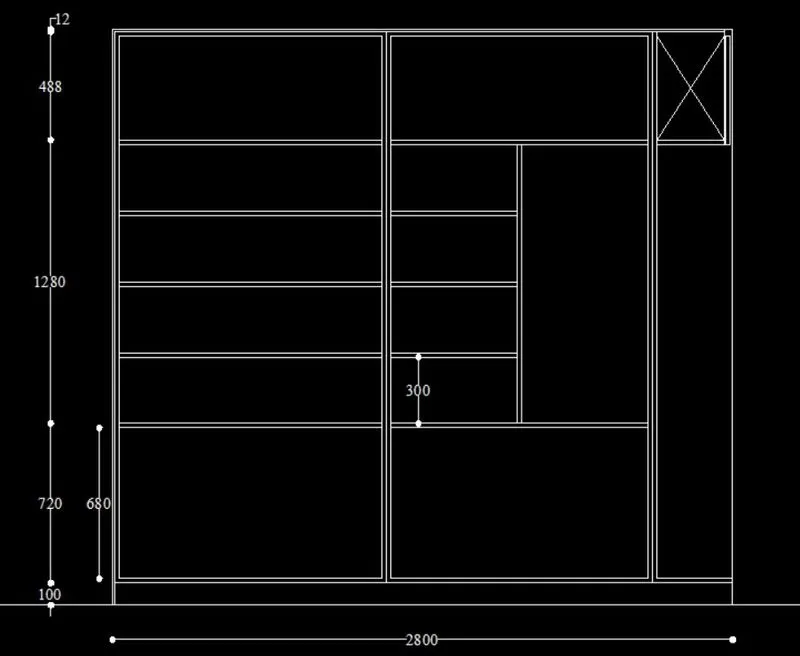
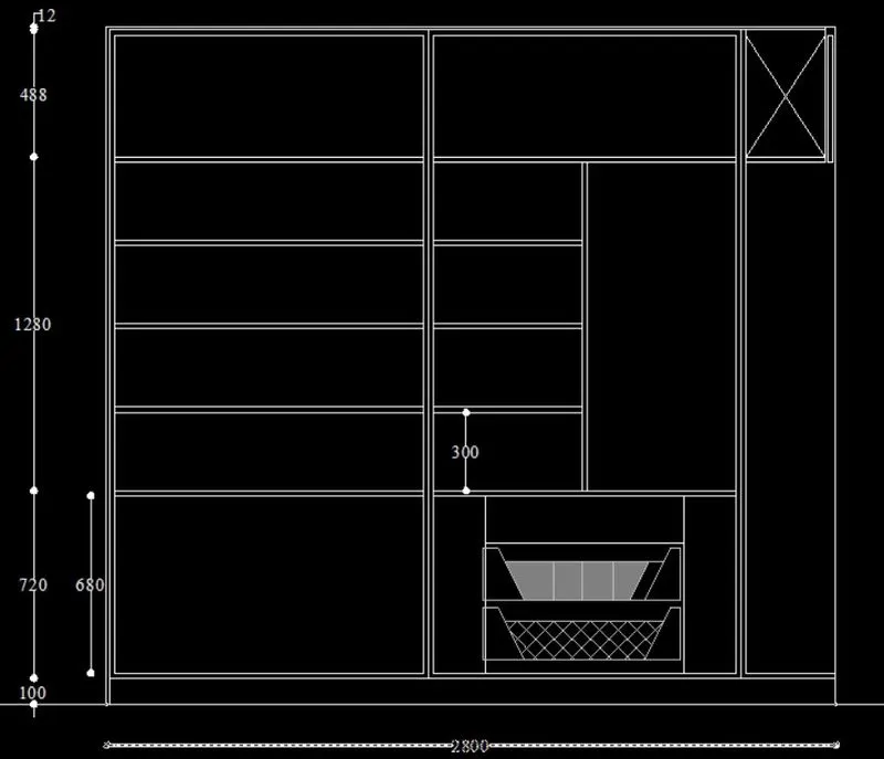
step-22: Type "L" line tool draft all the elements we required in the elevation.
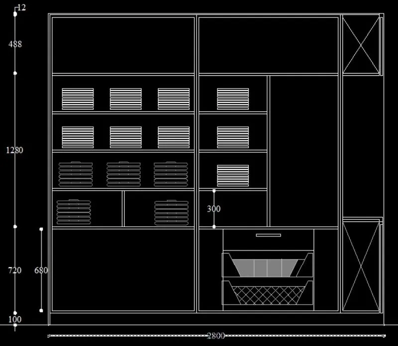
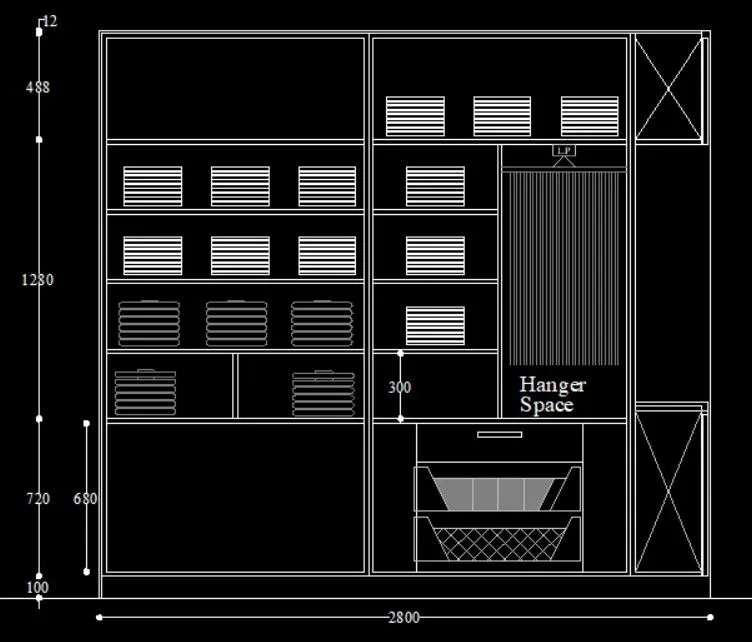
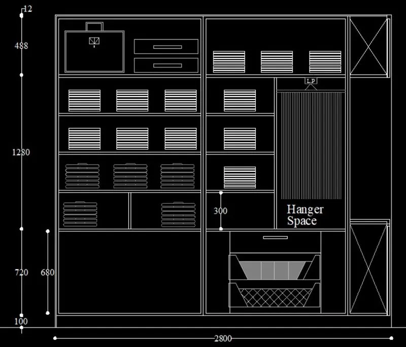
step-23: Type "DIMLIN" to mark all the dimensions for reference.
step-24: Type "DT" to text all the notes and titles.
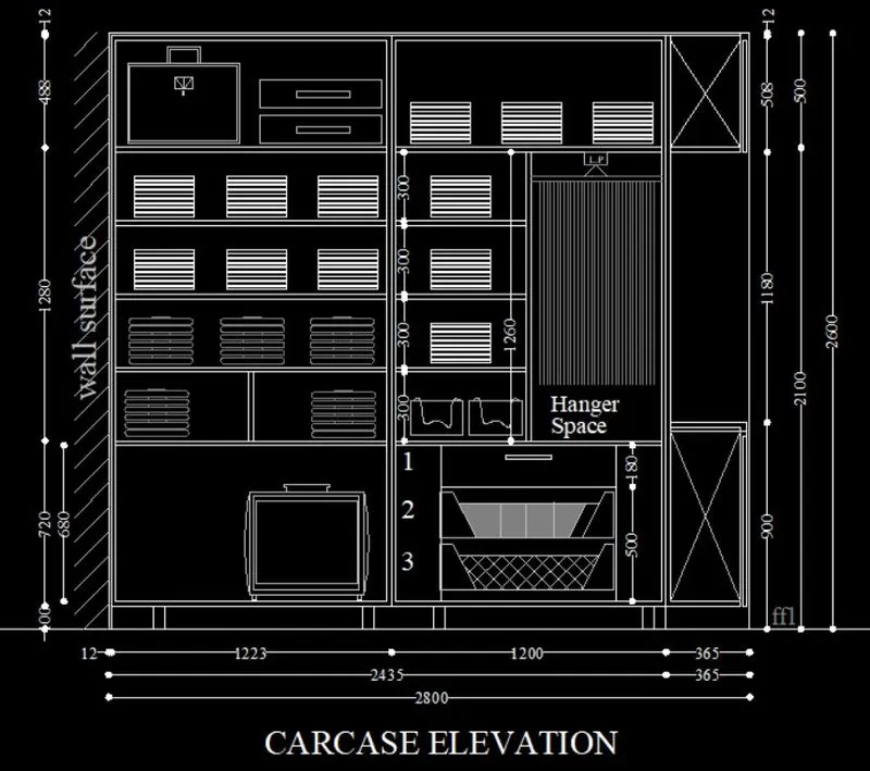
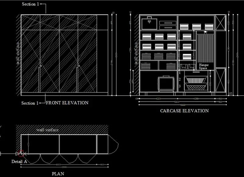
step-25: Type "O" to envoke offset tool to plot next element in the drawing.
step-26: Type "H" to hatch the wall surface.
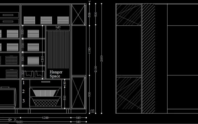
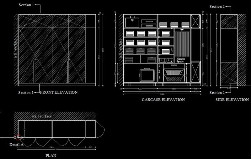
step-27: Type "O" to draft section of the wardrobe.
step-28: Type "CO" to copy Arc from the plan and paste it in section drawing.
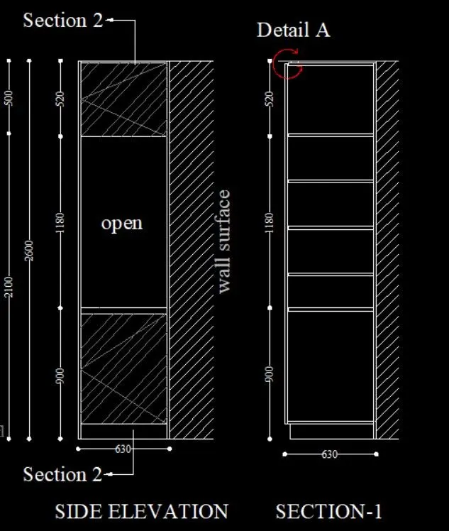
step-29: Type "O" to offsetting line from existing drawing and to plot section 2.
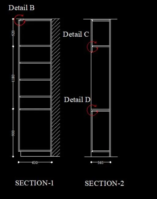
RESULT:
Drafting the elevation and sectional view of wardrobe by using AutoCAD. Each and every element in the given drawing was drafted.
Question-2:
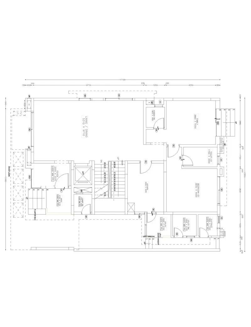
Aim: To draw the floor plan with refer to given diagram.
Introduction:
XLine: It means construction line. It has infinty edges we used for making wall. By typing "XL" on command line we envoke this tool.
Line: It connects one point to another points. Used to draft various elements.
Trim: This modification tool helps to cut extended edges on the drawing. And to trim inbetween two line or elements. "TR" command to envoke this tool.
Extend: It is also a modification tool, if we have some broken edges or need to extend some portion towards anonther element. "EX" command to envoke the tool.
Offset: Offset the existing element with certain distance. this tool avoid to create new parallel elements.
Layer: Each and every elements has unique property and unique style. This layer tool helps to organize those. Line weight, line style, colour gradient, freeze, lock. it has numerous benefits in Auto CAD drafting.
Hatch: Hatching helps to fill the voids with certain texture on it. If we draft wall means, we mention the brickwork details with the help of hatching.
Circle: Used to make circle elements in the sheet. Type "C" to envoke this tool. Here it is used to draft door.
Procedure:
step-1: Import Floor Plan PDF file in to Auto CAD file.
step-2: I am using Auto CAD 2007, Here PDFIMPORT command doesn't works. So, I used to import PDF from online converter tool.
step-3: After Importing PDF file Type "BASECOPY" to copy the imported AutoCAD file to paste another specified sheet set.
step-4: Select the object we required and enter base point of 0,0.
step-5: Open new drawing sheet and paste with reference of 0,0.
step-6: Type "ERASE" command to erase the all elements which was not required.
step-7: Type "SC" to scale the imported object to required scaling object.
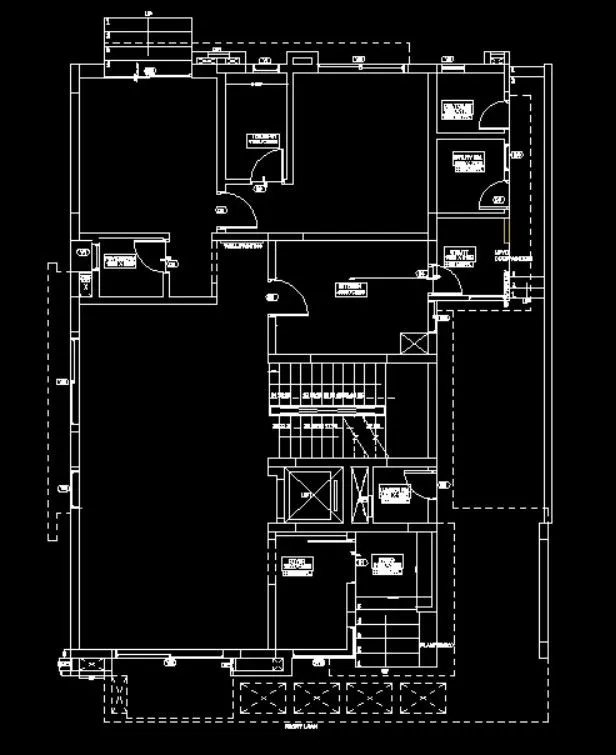
step-8: Type "DIMLIN" to mark all linear dimensions on the sheet.
step-9: TYpe "DT" to text specified notes on the drawing.
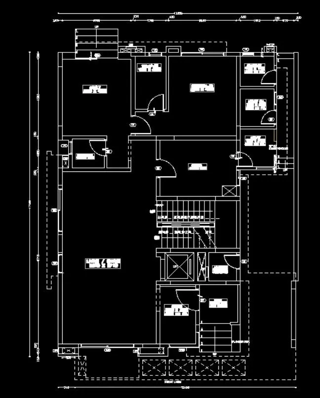
RESULT:
Drafted the floor plan from given PDF by using AutoCAD. I attach the PDF file also. Please find an attachment below in this sheet.
Question-3:
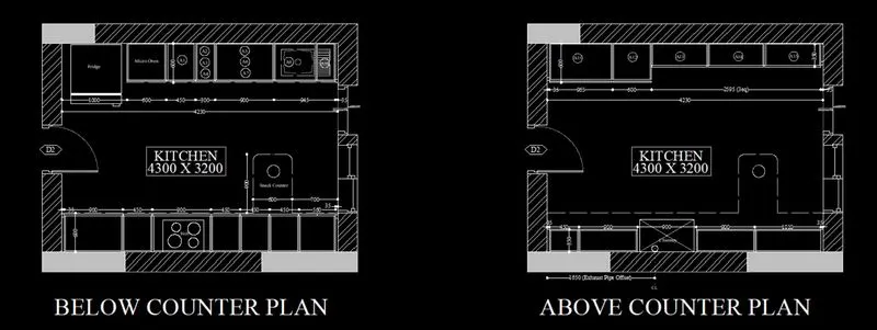
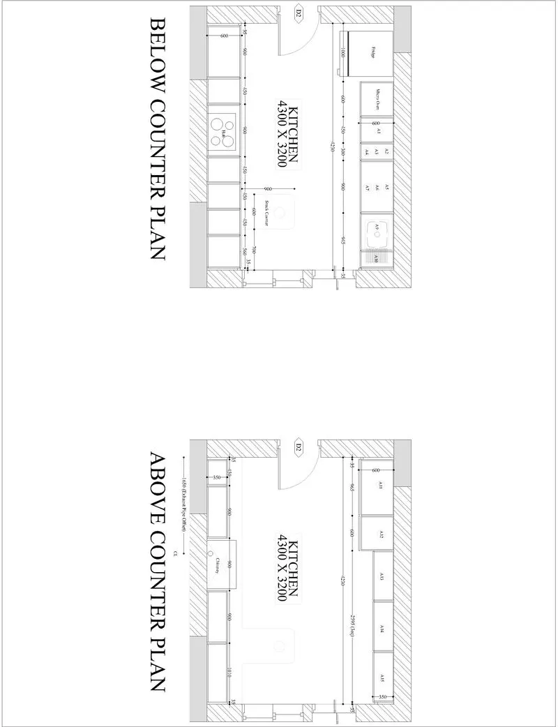
Aim: To draft Kitchen plan of above and below counter area.
Introdction:
XLine: It means construction line. It has infinty edges we used for making wall. By typing "XL" on command line we envoke this tool.
Line: It connects one point to another points. Used to draft various elements.
Trim: This modification tool helps to cut extended edges on the drawing. And to trim inbetween two line or elements. "TR" command to envoke this tool.
Extend: It is also a modification tool, if we have some broken edges or need to extend some portion towards anonther element. "EX" command to envoke the tool.
Offset: Offset the existing element with certain distance. this tool avoid to create new parallel elements.
Layer: Each and every elements has unique property and unique style. This layer tool helps to organize those. Line weight, line style, colour gradient, freeze, lock. it has numerous benefits in Auto CAD drafting.
Hatch: Hatching helps to fill the voids with certain texture on it. If we draft wall means, we mention the brickwork details with the help of hatching.
Circle: Used to make circle elements in the sheet. Type "C" to envoke this tool. Here it is used to draft door.
Procedure:
step-1: Type "UN" to select the units we required "DECIMAL" with precision of 0 and Millimeter.
step-2: Type "LIMITS" to set the limit of the sheet.
step-3: Type "XL" constrcution line to plot and select "H" and "V" angle.
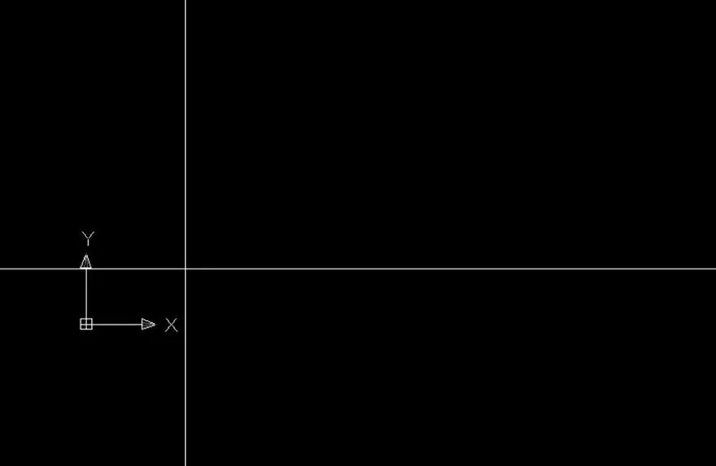
step-4: Type "O" to envoke offset tool to mark wall thickness.
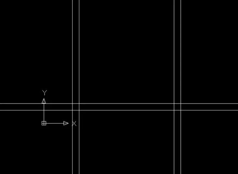
step-5: Type "TR" Trim all extended edges on the drawing sheet.
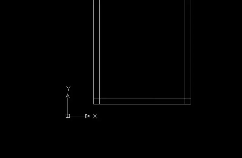
step-6: Type "O" offset to draft remaining elements in the kitchen.
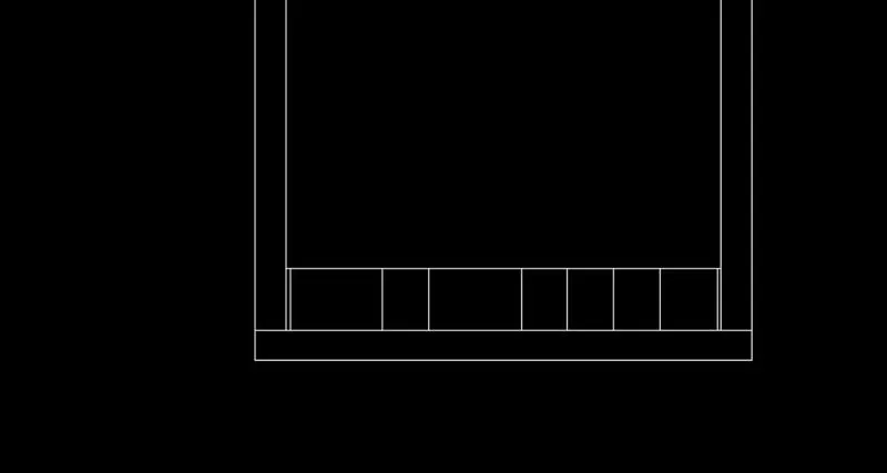
step-7: Load Dashed line in linetype manager and plot in the sheet.
step-8: Type "O" offset to plot all the lines.
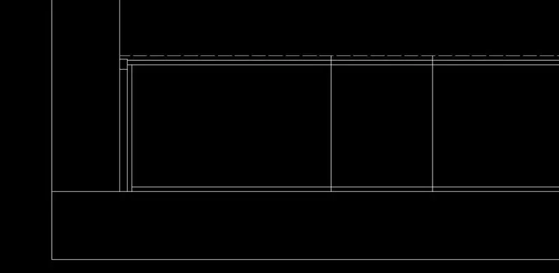
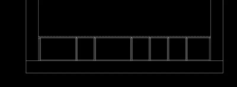
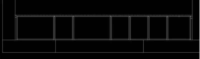
step-9: Type "DIMLIN" to mark all the dimensions on the sheet.
step-10: Type "C" circle to draft hob.
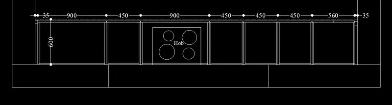
step-11: TYpe "H" hatch to wall thickness.
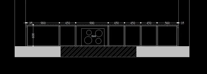
step-12: Type "O" offset to draft another side elements.
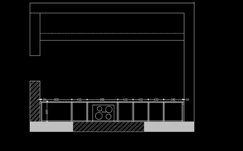
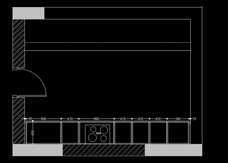
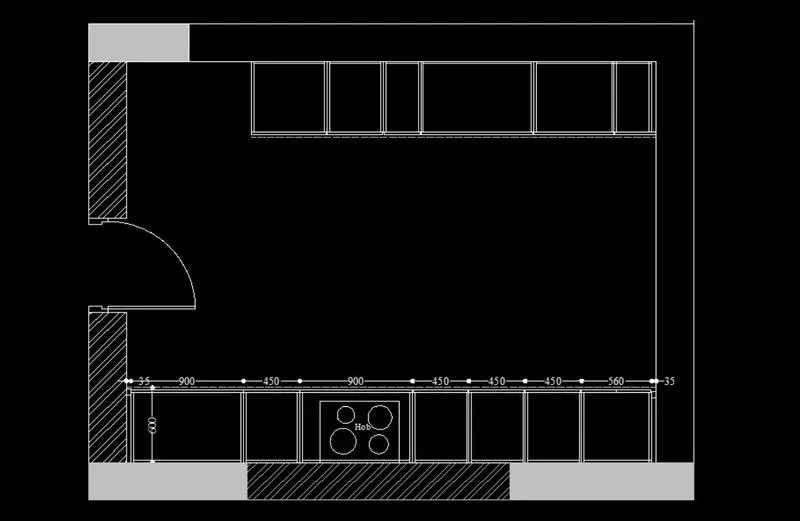
step-13: Type "L" line tool to draft fridge and another elements.
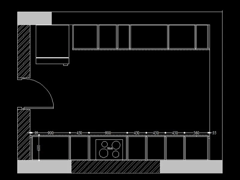
step-14: Type "C" circle to plot notes.
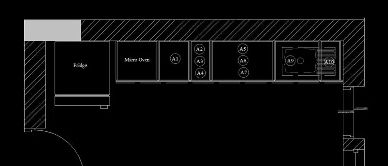
step-15: Type "DT" text to mark all the notes in the sheet.
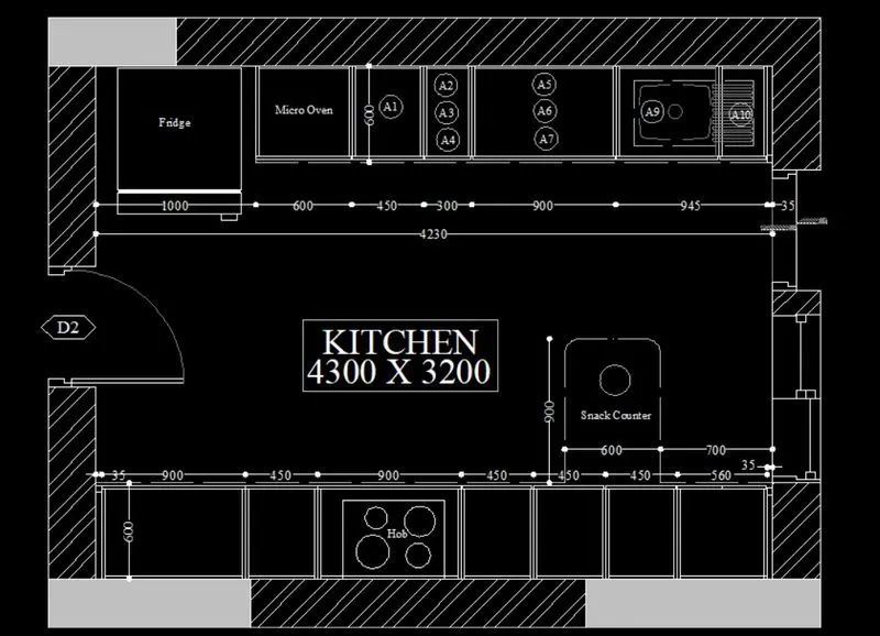
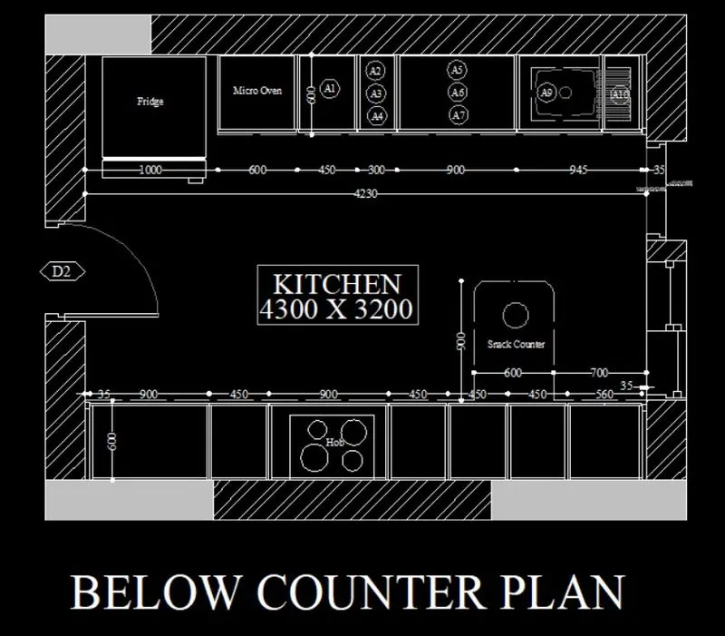
step-16: Type "CO" to copy the previously draft the objects and paste it nearby to draw another object.
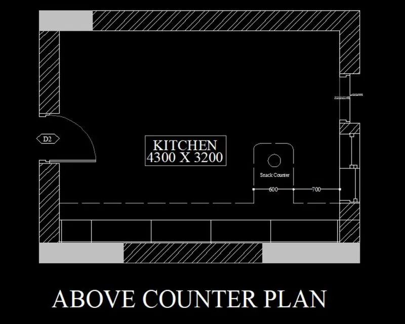
step-17: Type "ERASE" to erase all elements which doesn't required.
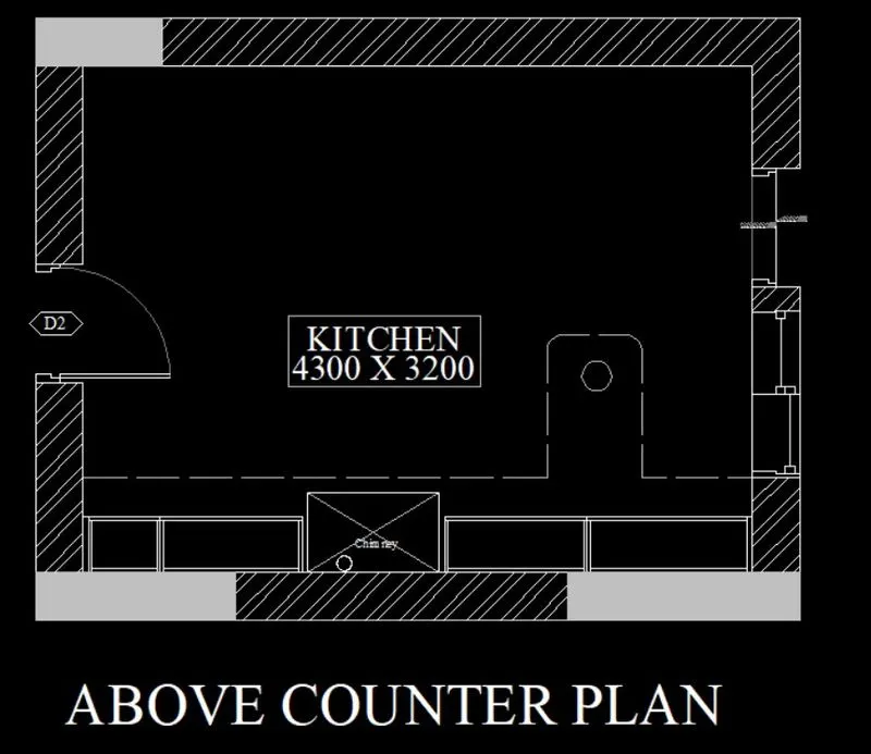
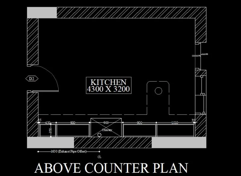
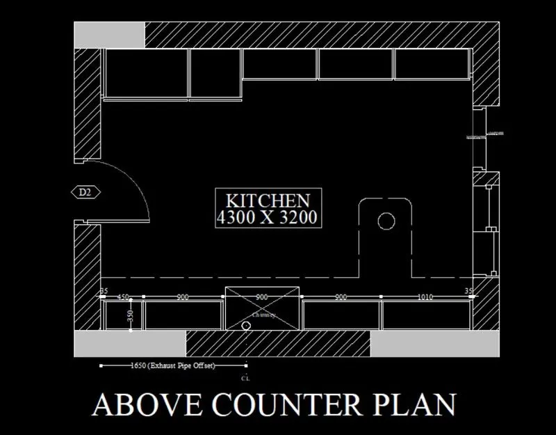
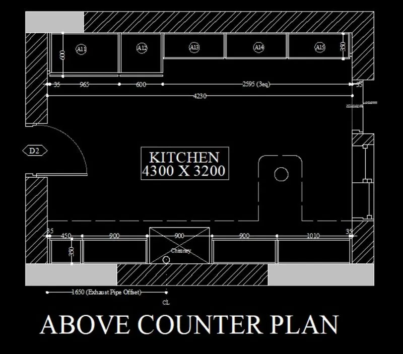
RESULT:
Drafted kitchen plan of above and below counter area by using AutoCAD.
Question-4:
Aim: To draft column details by usinf AutoCAD.
Introduction:
XLine: It means construction line. It has infinty edges we used for making wall. By typing "XL" on command line we envoke this tool.
Line: It connects one point to another points. Used to draft various elements.
Trim: This modification tool helps to cut extended edges on the drawing. And to trim inbetween two line or elements. "TR" command to envoke this tool.
Extend: It is also a modification tool, if we have some broken edges or need to extend some portion towards anonther element. "EX" command to envoke the tool.
Offset: Offset the existing element with certain distance. this tool avoid to create new parallel elements.
Layer: Each and every elements has unique property and unique style. This layer tool helps to organize those. Line weight, line style, colour gradient, freeze, lock. it has numerous benefits in Auto CAD drafting.
Hatch: Hatching helps to fill the voids with certain texture on it. If we draft wall means, we mention the brickwork details with the help of hatching.
Circle: Used to make circle elements in the sheet. Type "C" to envoke this tool. Here it is used to draft door.
Procedure:
step-1: Type "UN" to set the units of the sheet.
step-2: Type "LIMITS" to set the limit of the sheet.
step-3: Type "REC" to plot.

step-4: Type "OFFSET" to envoke offset the rectangle.

step-5: Type "F" to envoke fillet tool with radius of 1" and select the edges.
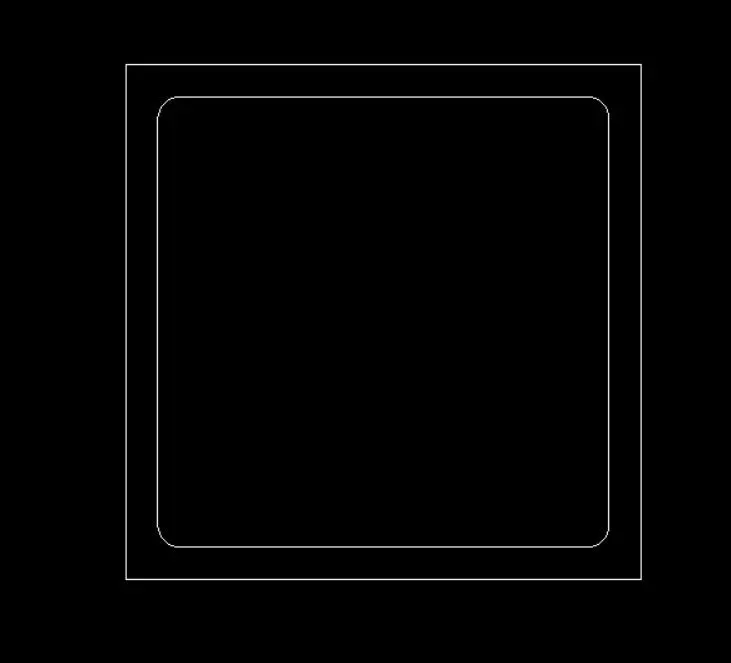
step-6: Type "DONUT" command with 0' inner circle and 1" outer diameter.
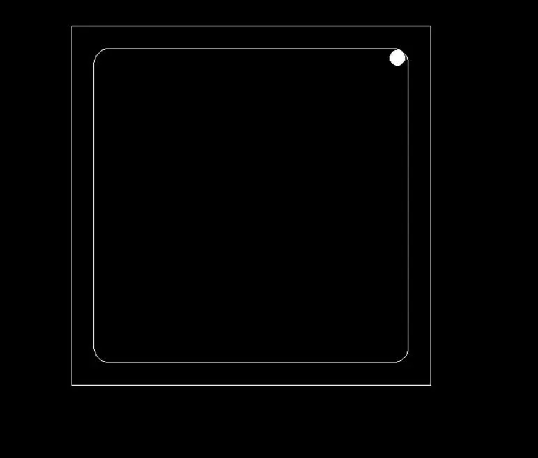
step-7: Type "AR" array with Row of 4 and distance of 5" angle of 180 degree.
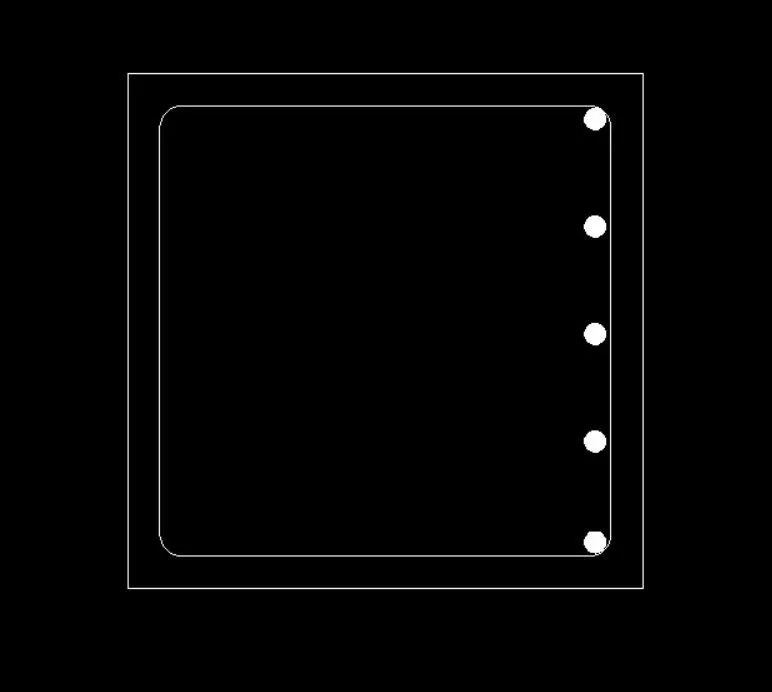
step-8: Type "MIRROR" mirror command to plot reinforcement to opposite edges.
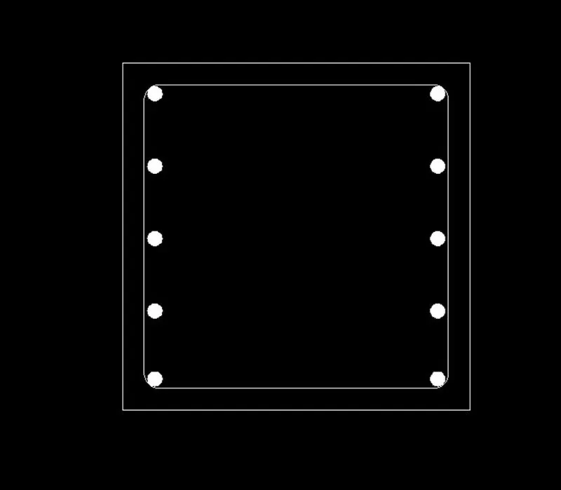
step-9: Type "AR" Array tool with 4 columns and angle of 0 and offset distance of 5"
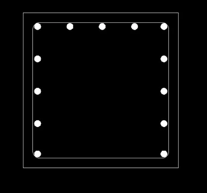
step-10: Type "MIRROR" to mirror the reinforcements.
step-11: Type "L" to line tool to connect ties.
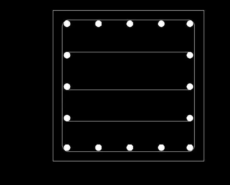
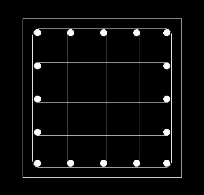
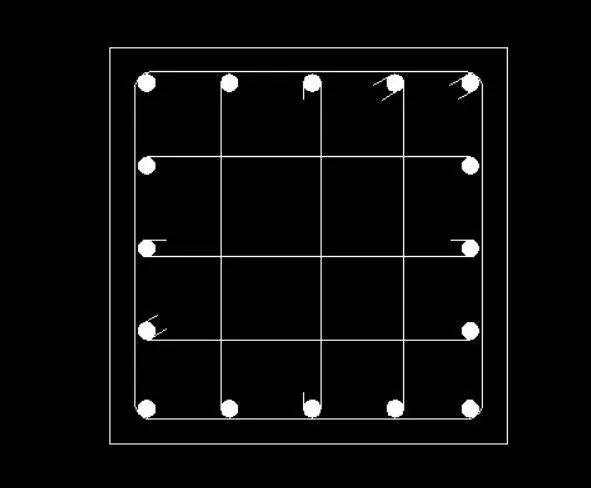
step-12: Type "REC" tool to plot column details.

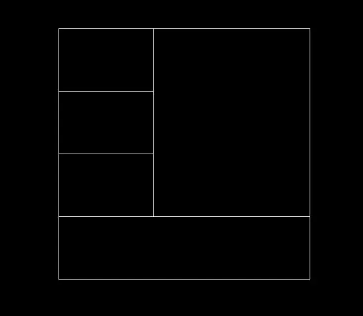
step-13: Type "DT" text tool to note all the texts.
step-14: TYpe "CO" copy the reinforcements and paste in to this specified area of details.
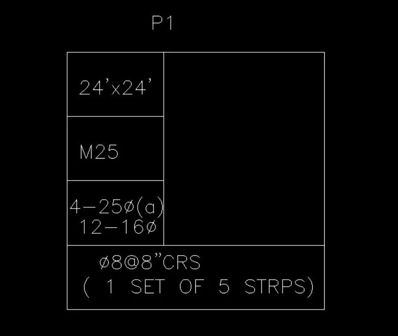
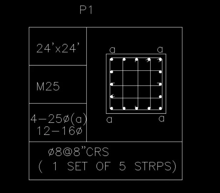
step-15: Type "CO" copy the P1 sheet and paste in to sheet.
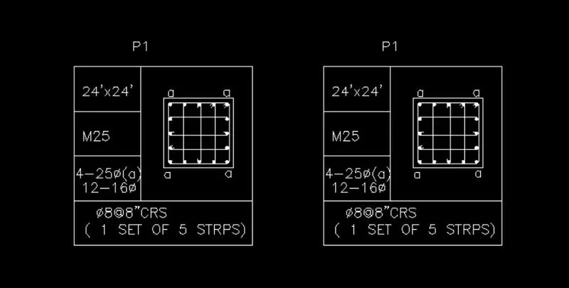
step-16: Type "ED" edit tool to modify the texts.
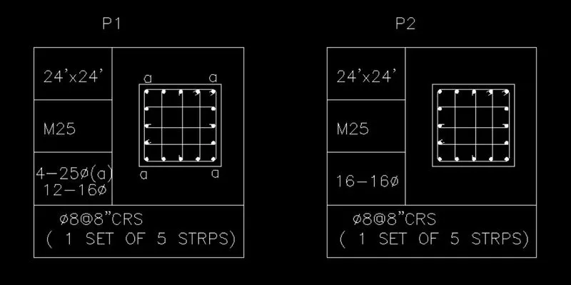
step-15: Type "CO" copy the P1 and P2 sheet and paste in to sheet.
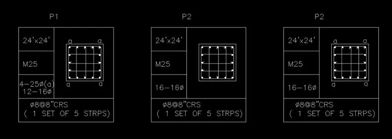
step-16: Type "ED" edit tool to modify the texts.
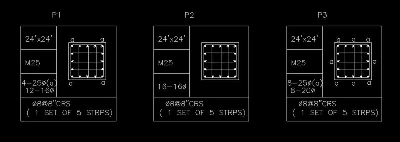
RESULT:
Finally, Drafted the column details by using AutoCAD.
Question-5:
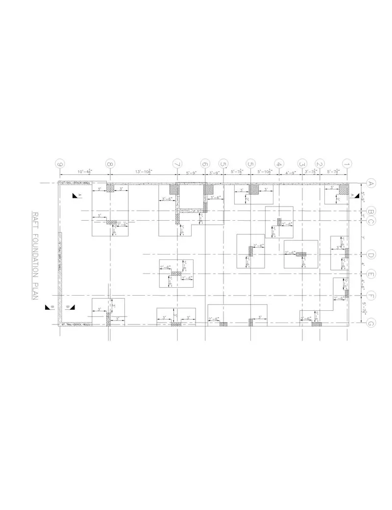
Aim: To draft Raft layout by using Auto CAD and mention all the column dimensions and footing dimensions.
Introduction:
XLine: It means construction line. It has infinty edges we used for making wall. By typing "XL" on command line we envoke this tool.
Line: It connects one point to another points. Used to draft various elements.
Trim: This modification tool helps to cut extended edges on the drawing. And to trim inbetween two line or elements. "TR" command to envoke this tool.
Extend: It is also a modification tool, if we have some broken edges or need to extend some portion towards anonther element. "EX" command to envoke the tool.
Offset: Offset the existing element with certain distance. this tool avoid to create new parallel elements.
Layer: Each and every elements has unique property and unique style. This layer tool helps to organize those. Line weight, line style, colour gradient, freeze, lock. it has numerous benefits in Auto CAD drafting.
Hatch: Hatching helps to fill the voids with certain texture on it. If we draft wall means, we mention the brickwork details with the help of hatching.
Circle: Used to make circle elements in the sheet. Type "C" to envoke this tool. Here it is used to draft door.
Procedure:
step-1: Type "UN" to units the sheet set
step-2: Type "LIMITS" limit the sheet set.
step-3: Type "XL" command to envoke construction line tool to plot horizontal and vertical lines.
step-4: Type "O" offsetting the objects with specified distance given in the diagram.
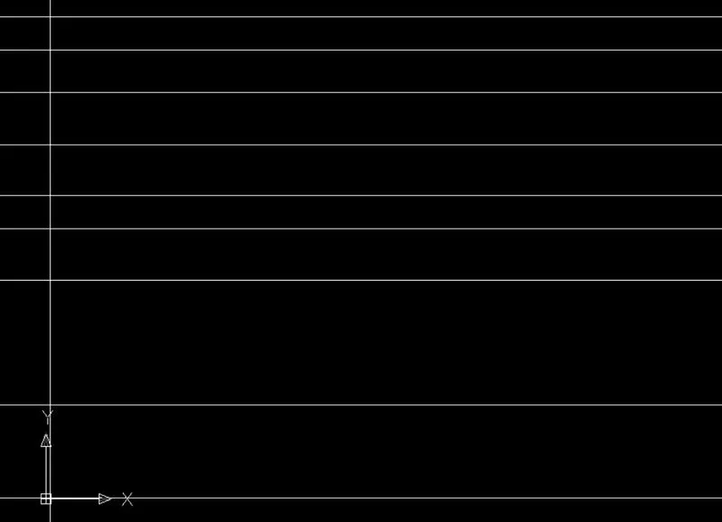
step-5: Type "TR" trim all the extened edges in the drawing.
step-6: Type "LINETYPE" to open linetype manager dialogue box
step-7: Select the Center line type to marl center line of the footing and grid.
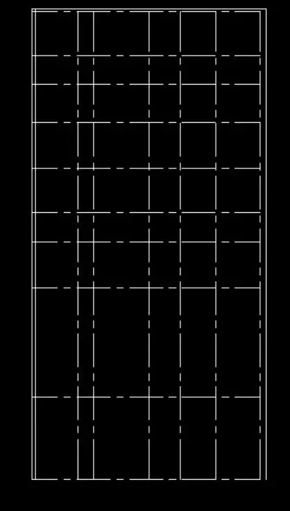
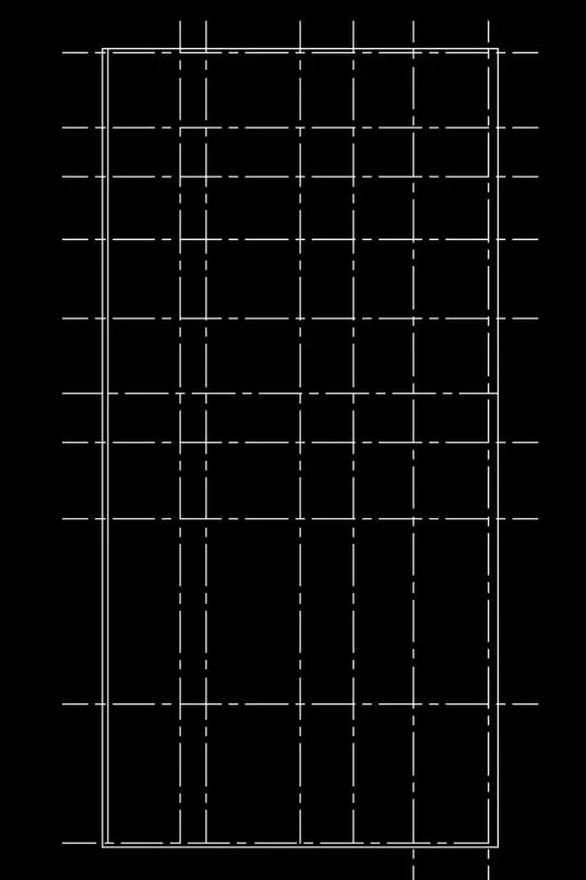
step-8: Type "C" circle to plot grid titles.
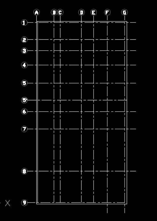
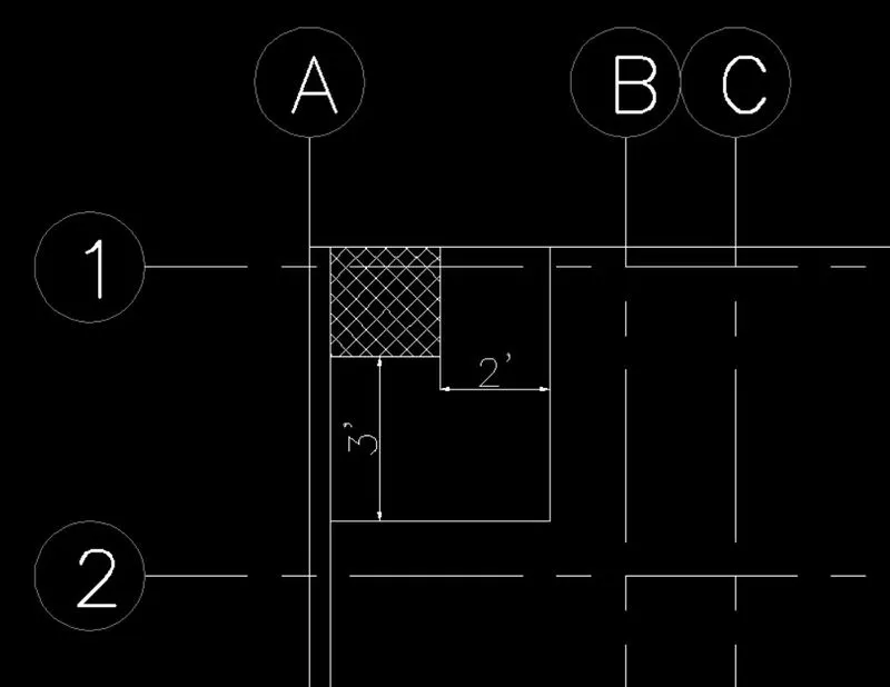
step-9: Type "L" to draft column size of 24" X 24"
step-10: Type "H" Hatch the column
step-11: Type "O" offset with reference to column to draft raft size.
step-12: Type "L" to draft column size of 9" X 24"
step-13: Type "H" Hatch the column
step-14: Type "O" offset with reference to column to draft raft size.
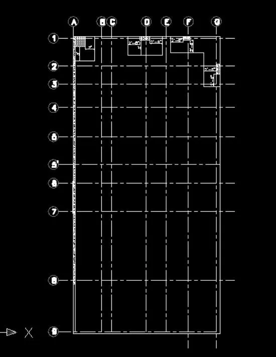
step-15: Type "L" to draft column size of 9" X 18"
step-16: Type "H" Hatch the column
step-17: Type "O" offset with reference to column to draft raft size.
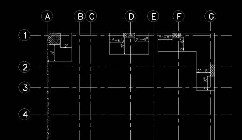
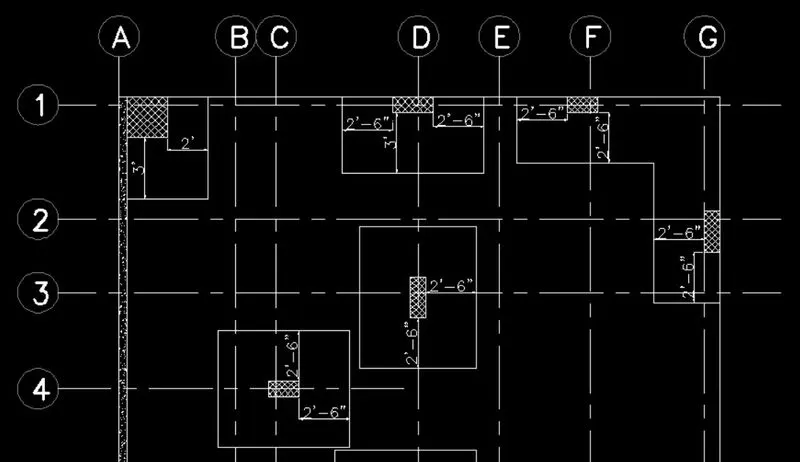
step-18: Type "L" to draft column size of 18" X 18"
step-19: Type "H" Hatch the column
step-20: Type "O" offset with reference to column to draft raft size.
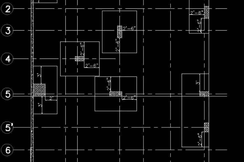
step-21: Type "L" to draft column size of 9" X 24"
step-22: Type "H" Hatch the column
step-23: Type "O" offset with reference to column to draft raft size.
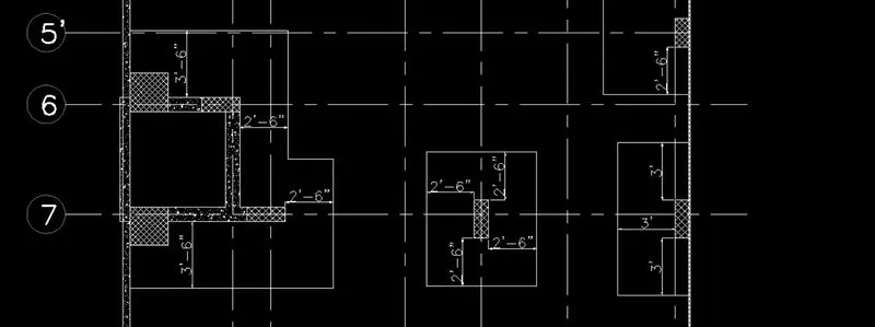
step-24: Type "L" to draft column size of 24" X 9"
step-25: Type "H" Hatch the column
step-26: Type "O" offset with reference to column to draft raft size.
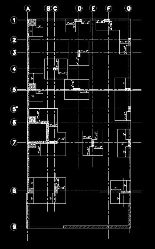
step-27: Type "DIMLIN" to mark all the linear dimensions with grid to grid reference.
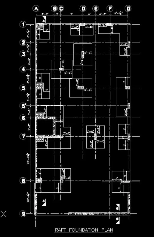
step-28: Type "DT" with justify of Left and angle zero of text height 5".
step-29: Type 9" Thk. wall to mention in the drawing.
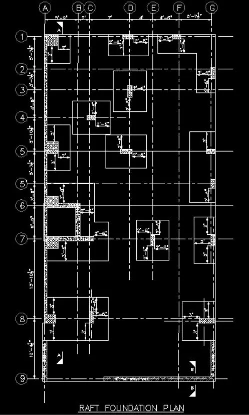
RESULT:
Drafted the Raft foundation layout with center line marking reference and also locate the columns.