Creating a Wardrobe detailed drawing, Floor Plan, Kitchen Layout and Column Detail using AutoCad
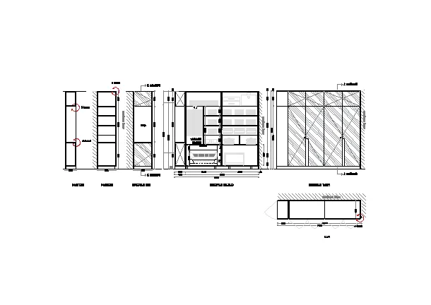
AIM: Draw the elevation and details of a wardrobe as shown in the Figure below. After sketching, you need to provide the dimensions and text with the use of layers. Use proper text styles and dimension methods to document it. Also, assume dimensions, wherever needed.
Note: All dimensions are in mm.
PROCEDURE:
STEP-1:
- Select units as a millimeteres and decimals 0.0
- set the limmax as a 100m,100m
- fant style as arial in anotate section.
STEP-2:
- With using as a line command draw a rectangle with dimentions as 2810,2588.
- with using line line command partions with thickness of 20mm partioans.
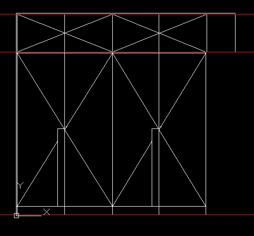
- outer lines will draw as per given dimentions and partions made with help of offset command
- and extra unwanted lines are removed by the help of trim command
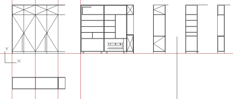
- draw a layout with line and offset cammand after thaht add the objects which are mention inside the cuboard.
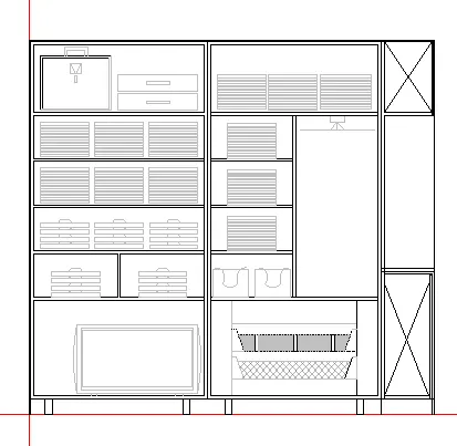
- with using mtext command are using through ribbion > annotation > select text( single text are multi-text)
- with using copy and move command objects are desined are arranged
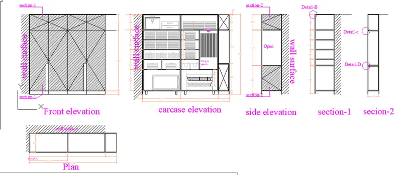
- dimmentions are added through the command of DIMLINEAR and DIMCONTINUE.
- wall merged area should be marked as a cross lines.
RESULTS:
AIM:
Draw the floor plan as shown in the Figure. Use the proper drafting tools to sketch the plan. Do not hatch or draw the furniture. You need to draw the floor plan with the following:
Note: You can also import the Floor_Plan.pdf into your current drawing and start working on the project. You need to scale the imported pdf file using reference option. All dimensions are in mm.
- Walls (Exterior and Interior)
Wall Thickness: Exterior Wall- 230mm, Interior Wall: 150 mm (Wherever Required)
- Doors and Windows: Assume the size of the doors and window.
2.1 Stairs: Tread-300mm, Riser-150mm
- Insert Text wherever required
- Insert the dimensions using proper dimension techniques
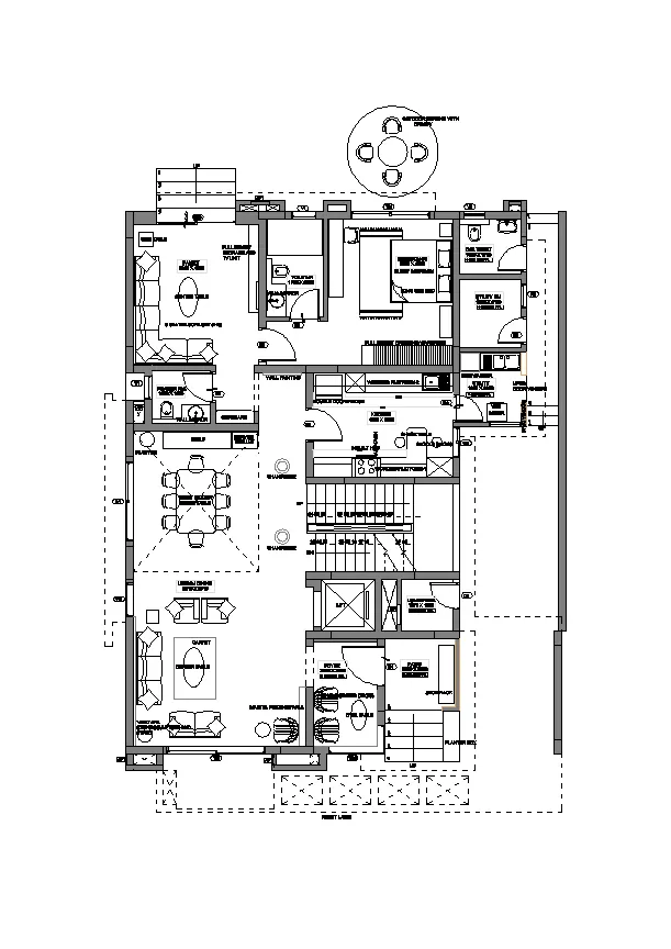
PROCEDURE:
STEP-1:
- Select units as a millimeteres and decimals 0.0
- set the limmax as a 100m,100m
- fant style as arial in anotate section.
STEP-2:
- with using XREF command insert pdf file as a block
- after remove the frame using xframe command.
- and after convert that pdf block into explode dwf file
- mesure as requires before thaht scale the that drawing with referance point in SCALE command.
- after we getting all dimmentions draw the the lines with LINE command
- give the pation walls as a 150mm and after that outer walls as 230mm
- with using FILLET and OFFSET command give the wall thickness as per dimentions
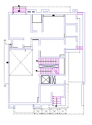
- after that add the doors and windows with using draw the that objects with TRIM and LINE commands
STEP-2:
- while drawing a plan devide the plan with LAYERS command
- like walls,doors,windows,text,dimentions and stairs.
- after that add the furniture using ADC( AUTOCAD DESIGN CENTER)
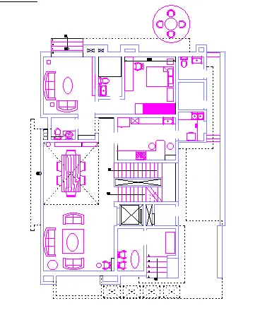
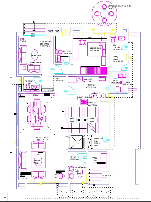
- then add the dimentions with the DIMLINER command
- add text with using MTEXT command
- add tangents with QTANGENT command.
RESULTS:
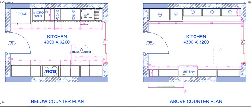
AIM: Create the Kitchen Layout as shown in the Figure below. Also, use proper dimension techniques to dimension the kitchen layout. Also, insert text wherever required. All dimensions are in mm.
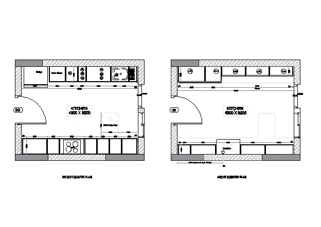
PROCEDURE:
STEP-1:
- Select units as a millimeteres and decimals 0.0
- set the limmax as a 100m,100m
- fant style as arial in anotate section.
STEP-2:
- with using line command draw a required as per the dimentions given in the drawing.
- partions made with TRIM,OFFSET and EXTEND command.
- pation thickness given as 20mm and wall thickness is 230mm
RESULTS:
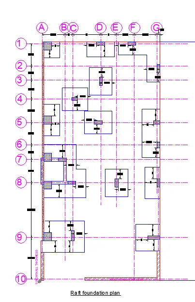
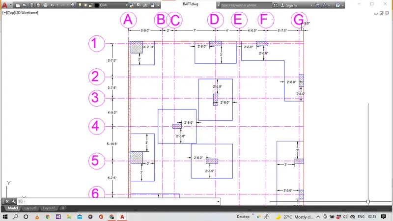
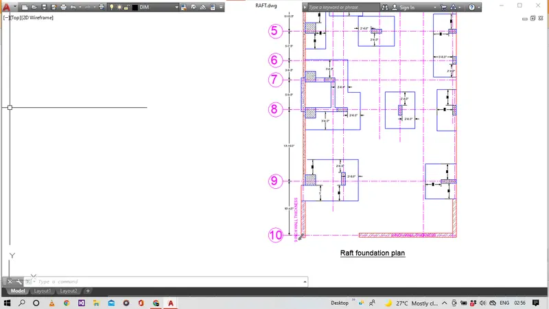
AIM:Draw the Raft Layout as shown in the Figure. Assume the column size as per your knowledge. You can take the sizes as: 24”x24”, 9” x 24”, 9” x 18”, and 9’ x 24”. You can import the raft_foundation.pdf to ensure the missing dimensions.
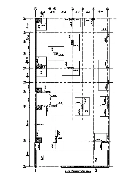
PROCEDURE:
STEP-1:
- Select units as a millimeteres and decimals 0.0
- set the limmax as a 100m,100m
- fant style as arial in anotate section.
STEP-2:
- import the pdf with the help of the XREF command
- make that pdf into black and EXPLODE it after that scale the that drawing with reference option in SCALE command.
- mesure the wanted information through that.
- make line as per given dimentions in reference pdf.
RESULTS: