Creating a Wardrobe detailed drawing, Floor Plan, Kitchen Layout and Column Detail using AutoCad
ANS 1.
AIM :-
To draw the elevation and details of a wardrobe as shown in the figure below and also provide the dimensions and text with the use of layer.
INTRODUCTION :-
AutoCAD is a commercial computer-aided design (CAD) and drafting software application. It was developed and marketed by Autodesk . AutoCAD was first released in December 1982 for desktop as a desktop app to work ,draft ,draw ,visualize and many more features.
PROCEDURE :-
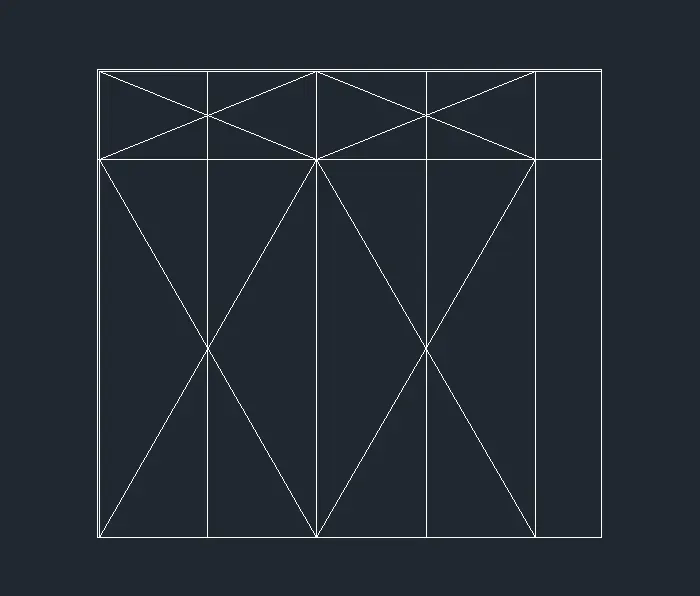
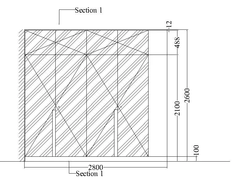
a.Procedure for creating FRONT ELEVATION
1.Select unit in mm and enter page size as 10000x10000
2.Select rectangle tool and draw rectangle of dimension 2600 ,2800 .
3.Use explode tool to explode the rectangle and use offset tool with 12 units from the top line and again offset 500 unit from the same top line
4.Again offset left line with 12 unit and then offset the right side line with 365 units and from the drawn offset line again offset with unit 608.75 and draw 3 lines.Again offset 100units from the bottom
5.Use trim tool to trim the outer edges.
6. For drawing the lines use the line tool and draw diagonal lines.
7. Now for Texts and dimensions, go to layer properties and create two new layers with colour of choice and name them text and colour.
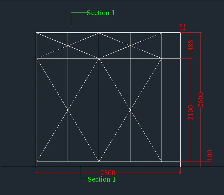
8.Select Dimension as current and go to dimension tool , dimension the drawn figure.
9.Now for Text ,Select the Text layer as set current then select text command and enter height of text as 100
10.Use multileader and then write the text.
11. For hatching,select the pattern as GOST-GROUND with scale factor of 20.
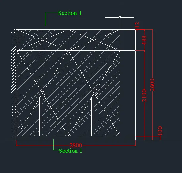
12.After than Plot the file.
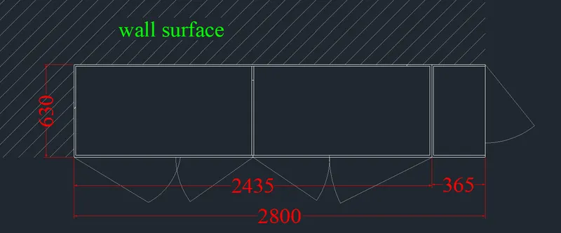
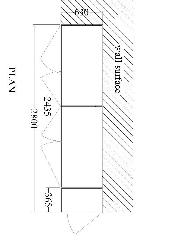
b.Plan :-
1.Bring the border lines down from Elevation for plan.
2.Draw horizontal line and offset 630 from the top , connect the lines.
3.Then again offset top line with 12units, right line 365 units and same line with 1211.5 units.
4.Use trim tool to trim objects
5.Dimension the plan and use text tool to write text.
6.Use hatch withscale factor 200 and hatch pattern as ANSI31.
c.CARCASE ELEVATION
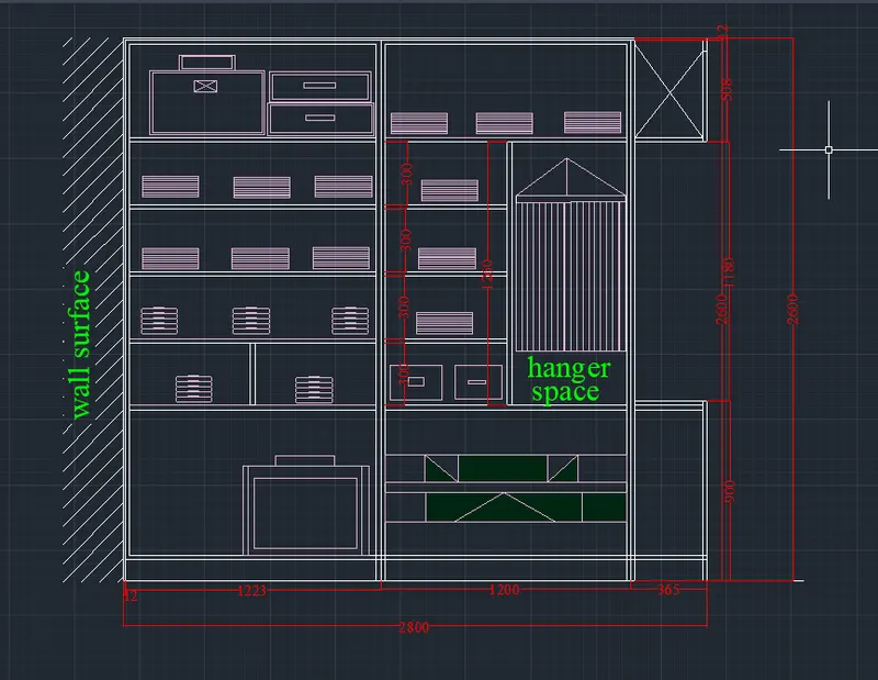
1.Extend the edge lines of Elevation and draw the lines.
2.Offset from top line 12 , 500, 1780 ,2500, and also offset from the vertical line 12, 1235, 2435.
3.Now again offset from previous lines as 12 ,508, 320 ,320 ,320 ,680
4.Trim the external and unwanted lines.
5.Insert the blocks from INSERT -> Block .
6.Use text command to write the text and dimension command to dimension it.
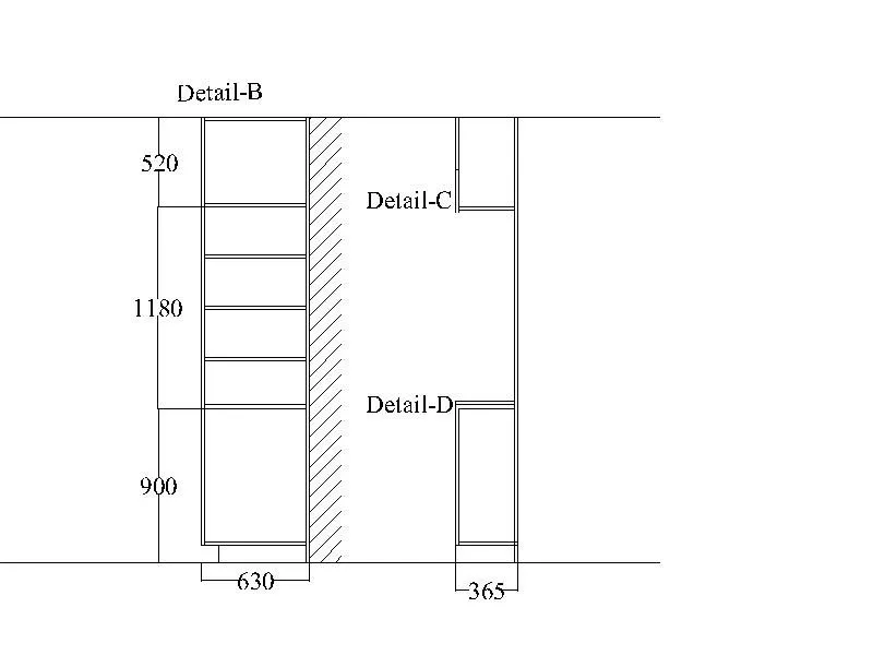
d.Side elevation
1.Extend the lines from carcase elevation and then draw the lines.
2.Then draw vertical line between the extended lines and offset it 20, 630 respectively.
3.Again offset the top line 20,520,1700 units.
4.Draw lines with line command.
5.Use text tool to write text and dimension tool to dimension the figure.
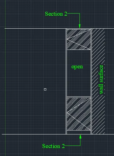
6.Use hatch tool to hatch the portion and select ANSI32 with scale factor 200.
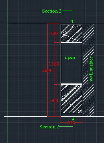
Section 1 same as side elevation
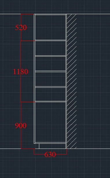
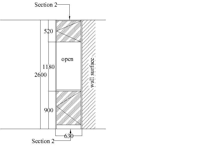
Section 2
1.extend line of section 1
2.Offset top line 20,520,1180 and bottom line 100,120
3.Also use offset for vertical line with offset 365 .Draw 20 unit inner lines
4.Trim unwanted lines and use dimension tool by selecting dimension layer as current to dimension to figure.
5 Use text tool to write the texts but first select text layer as current layer.
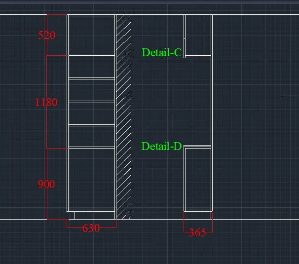
RESULT :-
Created figures are attached below :-
ANS 2.
AIM:-
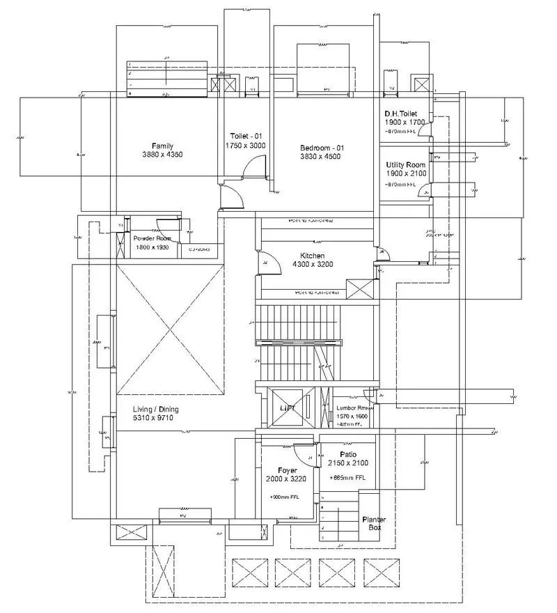
To create the given Floor plan layout using autocad software.
INTRODUCTION :-
AutoCAD is a commercial computer-aided design (CAD) and drafting software application. It was developed and marketed by Autodesk . AutoCAD was first released in December 1982 for desktop as a desktop app to work ,draft ,draw ,visualize and many more features.
PROCEDURE :-
1.Import the given PDF to scale and findout the dimensions.
2.INSERT->IMPORT PDF -> SELECT PDF -> select ok
3.Measure the dimension, scale it using reference option and then start drawing.
4.Select xline command ,Draw horizontal and vertical line respectively.
5.From left draw offset of 230 ,3880 , 230 ,1750 ,150,3830 ,2300,1900,150,500,230 respectively.
4.From bottom draw offset of 230,9710,230,1930,4350,230 repectively.
5.All the Offsets are drawn by refering after the drawn offset line.
6.After that trim unwanted lines.
7.Insert blocks of door and windows of size
D1 to D5 -950units
D6 to D8 - 450 units
W1 to W4 - 1000units
W5 to W7 - 510 units
V1 to V3 - 450 units
8.INSERT-> LIBRARIES-> SELECT ->Place on the screen.
9.Draw the other rectnagles as required in the figure .
10.For dashed lines ->Go to line properties -> Select CONTINOUS DASHED and then set current ok.
11.Provide them wherever required.
12.For texts and dimensioms,select text height as 100 and font as Arial.
13.Use Dimstyle to change dimension stylings.
14.Trim unwanted lines
15.Place texts and dimensions.
16.Plot the drawn figure in DWG.to JPG.format as paper size of Super VGA and then press ok
RESULT :-
Created floor plan is attachee below.
ANS3.
AIM:-
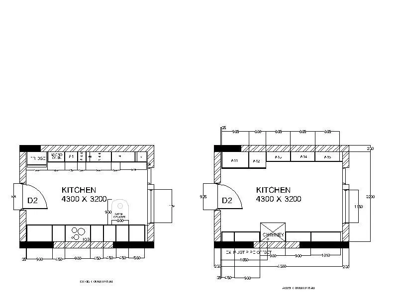
To create the kitchen layout as shown in the figure using Autocad software.
INTRODUCTION :-
AutoCAD is a commercial computer-aided design (CAD) and drafting software application. It was developed and marketed by Autodesk . AutoCAD was first released in December 1982 for desktop as a desktop app to work ,draft ,draw ,visualize and many more features.
PROCEDURE:-
1.Open new tab pressing cntrl+N
2.Draw rectangle of dimensions 4300 , 3200 and copy it.
3.Select offset and offset 230 both the rectangles.
4.Explode them , then use trim to trim as per figure.
5.Type insert and insert door blocks.
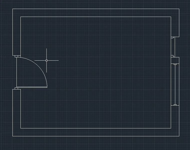
6.Place them in the center of left line of both rectangles.
7.For drawing boxes , select offset and do offset from bottom line of 350,10 ,now from left inner bottom line ,offset 35,450,900,900,900,1010,35
8.Similiarly,from top inner line,offset 600,10 ,350, and again from left inner top line offset 35 , 965 , 600 ,865,865,865 ,35.
9.Trim unwanted lines.
10.For window , Use insert and select window block ,place it between the lines for both of the rectangles.
11.Use trim tool again to trim .thats all for above counter plan
12.For below counter plan Again offset from bottom right line 35,560,700,1300,450,450,450,900,450,900,35
13 From bottom inner line offset 600 , 10
14.From top inner line offset 600,10 and from top right inner line offset 35,945,300,900,300,450,600,1000.
15.Trim Unwanted lines
16.For writing text in both select text height 200, text font arial and write.
17.Dimension scale is 0.5 and then done.
18.For hatching, Use ANSI32 and SOLID to hatch selected parts in both and scale factor is 500.
RESULT :-
Created kitchen layout is attached below.
ANS4.
AIM:-
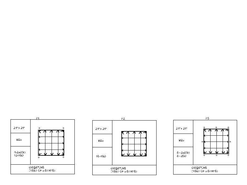
To sketch the column details using autocad software
INTRODUCTION :-
AutoCAD is a commercial computer-aided design (CAD) and drafting software application. It was developed and marketed by Autodesk . AutoCAD was first released in December 1982 for desktop as a desktop app to work ,draft ,draw ,visualize and many more features
PROCEDURE:-
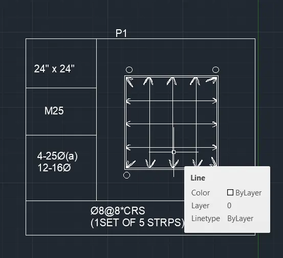
P1:-
1.Convert the given column size of 24" x 24" in mm.
2.Select rectangle ,draw rectangle of dimensions 600 x 600 .
3.Use offset tool and offset 10 the rectangle.
4.Select and explode then draw offset of 145,290,435 from left line.
5.Again offset from top line of 145,290,435.
6.Draw the required no. of circles and place then .
7.Now Draw a rectangle of dimension 2500 x 2500
8.Explode it and offset 400,900,1800,2200 from top line.
9.Again offset from left line as 600.
10.Trim the unwanted lines.
11.For text ,select text height as 50 and write required text.
12.Scale wherever required to fit the texts.
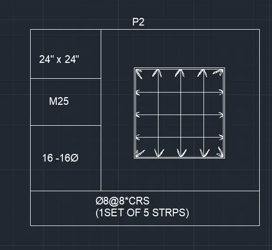
P2:-
1.Convert the given column size of 24" x 24" in mm.
2.Select rectangle ,draw rectangle of dimensions 600 x 600 .
3.Use offset tool and offset 10 the rectangle.
4.Select and explode then draw offset of 145,290,435 from left line.
5.Again offset from top line of 145,290,435.
6.Draw the required no. of circles and place then .
7.Now Draw a rectangle of dimension 2500 x 2500
8..Explode it and offset 400,900,1800,2200 from top line.
9.Again offset from left line as 600.
10.Trim the unwanted lines.
11.For text ,select text height as 50 and write required text.
12.Scale wherever required to fit the texts.
P3 :-
1.Convert the given column size of 24" x 24" in mm.
2.Select rectangle ,draw rectangle of dimensions 600 x 600 .
3.Use offset tool and offset 10 the rectangle.
4.Select and explode then draw offset of 145,290,435 from left line.
5.Again offset from top line of 145,290,435.
6.Draw the required no. of circles and place then .
7.Now Draw a rectangle of dimension 2500 x 2500
8.Explode it and offset 400,900,1800,2200 from top line.
9.Again offset from left line as 600.
10.Trim the unwanted lines.
11.For text ,select text height as 50 and write required text.
12.Scale wherever required to fit the texts.
RESULT :-
Created figure is attached below:-
ANS5.
AIM:-
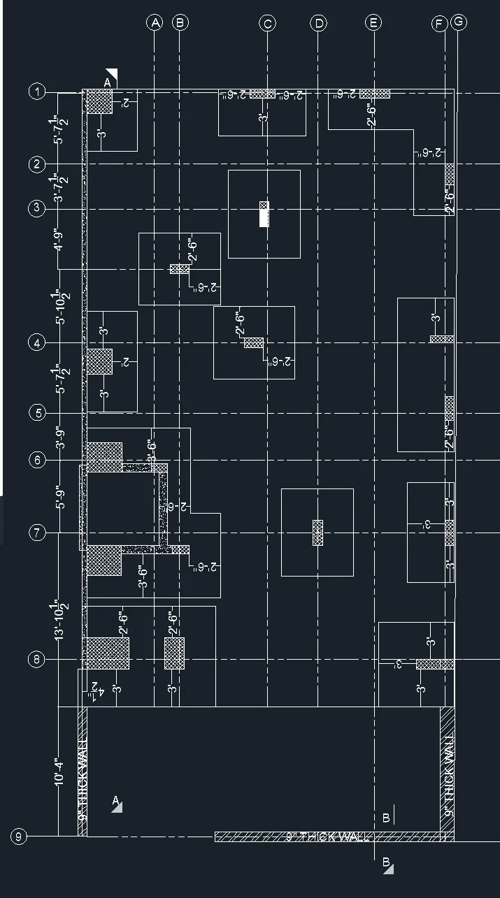
To draw the raft layout as given figure using autocad software.
INTRODUCTION:-
AutoCAD is a commercial computer-aided design (CAD) and drafting software application. It was developed and marketed by Autodesk . AutoCAD was first released in December 1982 for desktop as a desktop app to work ,draft ,draw ,visualize and many more features.
PROCEDURE:-
1.Import the pdf to refer the missing dimensions,using INSERT -> IMPORT PDF -> SELECT PDF -> OPEN.
2.Select X line ,Draw vertical and horizontal line.Trim extra lines to create a segment.
3.Use offset and offset 29" 7 1/2" from left line and 60' offset from bottom line.
4.Trim unwanted lines.
5.Select offset then offset starting from left line and keep selecting previous point.So offset 5'9", 2' , 7' 4' , 4'6", 5'7 1/2".
6.Again offset from top to 5'7 1/2", 3' 7 1/2", 4' 9", 5' 10 1/2", 5' 7 1/2", 3' 9", 5' 9", 13' 10 1/2", 10' 4 1/2".
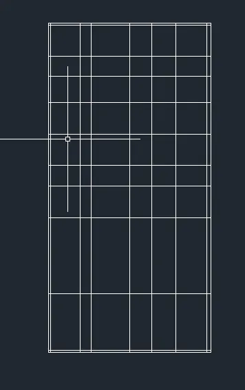
7.Create rectangle of 2' x 2' dimension ,explode it then offset 2' from right end and offset 3' from bottom end.Join the offseted lines.
8.Create polyline, with 10' , - 3'3" 6' -9", -6' -10 1/2", 3'-3",10' -1 1/2" and place it.
9.Create rectangles of dimensions 7' x 3' 9", 5'9" x 7' , 6'6" x 5'9" , 7' x 5'9" , 7' x 5'9", 4'6" x 12' 3", 4' x 8' , 5'9" x 7' , 3'9" x 8' ,10' 7 1/2" x 8' , 6' x 6'9".
10.Now hatch the created small rectangles .Use ANSI37 with scale factor of 20.
11.Again hatch using ANSI32 with scale factor 20. and also use AR-CONC to hatch and scale 1.
12.Now for dimension, select text height 5" and 8.5" and dimension the figure.
RESULT :-
Created layout is attached below