Creating a Wardrobe detailed drawing, Floor Plan, Kitchen Layout and Column Detail using AutoCad
INTRODUCTION: The main purpose of this challenge is to be familiar with the annotation and dimensioning command and parallelly help the students to set his/her hand on working with the AutoCAD software. The commands like dtext, line, fillet, trim, extend, explode, circle, offset, mtext, dimensions, pttype, hatch, rectangle, layer properties, and many more. This challenge has introduced the students to the problems faced while sketching up a section of any plan or substance, drafting a foundation plan, dimensioning, the importance of detailing, etc.
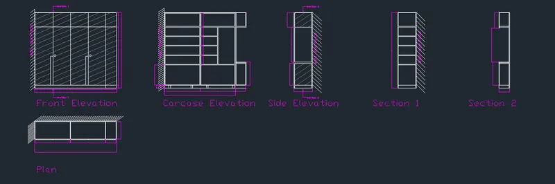
Draw the elevation and details of a wardrobe as shown in the Figure below. After sketching, you need to provide the dimensions and text with the use of layers. Use proper text styles and dimension methods to document it. Also, assume dimensions, wherever needed.
Note: All dimensions are in mm.
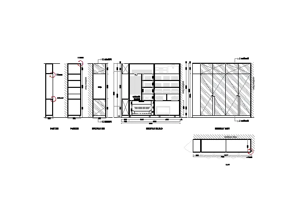
Procedure:
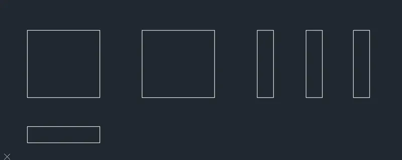
- Take the rectangle command and draw the outermost boundaries of the cabinet for all the sections, elevations, and plans.
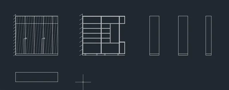
- Now take the offset command and draw the whole cabinet i.e., its section, plan, and elevation.
- Now draw a line at a 45-degree angle at the points where the array is required to denote the wall.
- Use array and take the path mode and finally create an array for denoting the wall where ever required.
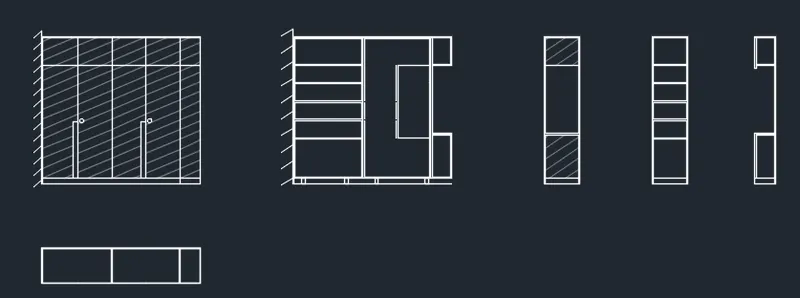
- Give the dimensions and labeling where ever required.
Results:
- The required section, elevation, and plan of the cabinet are formed.
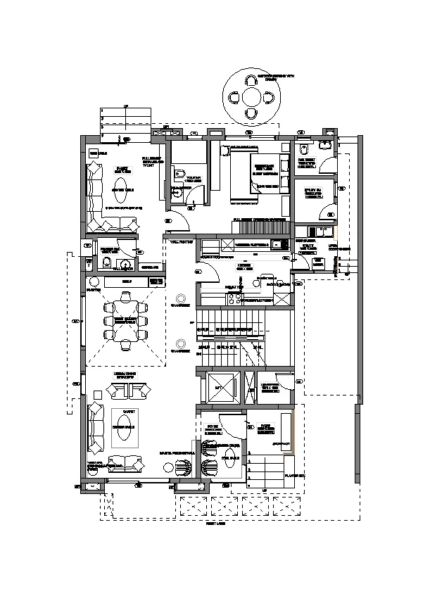
AIM: Draw the floor plan as shown in the Figure. Use the proper drafting tools to sketch the plan. Do not hatch or draw the furniture. You need to draw the floor plan with the following:
Note: You can also import the Floor_Plan.pdf into your current drawing and start working on the project. You need to scale the imported pdf file using the reference option. All dimensions are in mm.
- Walls (Exterior and Interior)
Wall Thickness: Exterior Wall- 230mm, Interior Wall: 150 mm (Wherever Required)
- Doors and Windows: Assume the size of the doors and window.
- Stairs: Tread-300mm, Riser-150mm
- Insert Text wherever required
- Insert the dimensions using proper dimension techniques
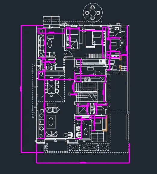
Procedure:
- Import the floor plan pdf.
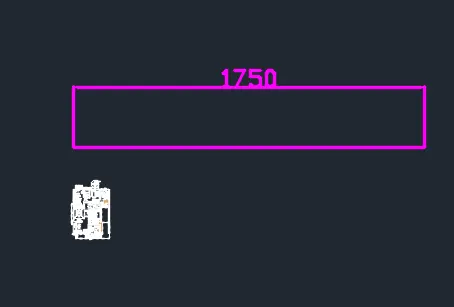
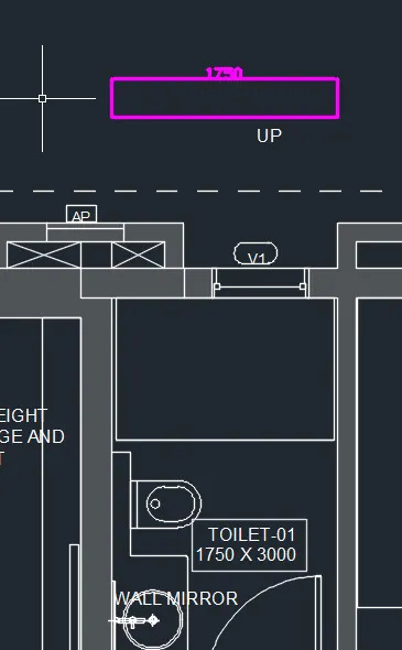
- Scale the whole plan using the reference of a line.
- Once the scaling of the plan is done check whether it's correct or not.
- Give the dimensions and labeling where ever required.
Results:
- The required plan according to the dimensions is formed.
AIM Create the Kitchen Layout as shown in the Figure below. Also, use proper dimension techniques to dimension the kitchen layout. Also, insert text wherever required. All dimensions are in mm.
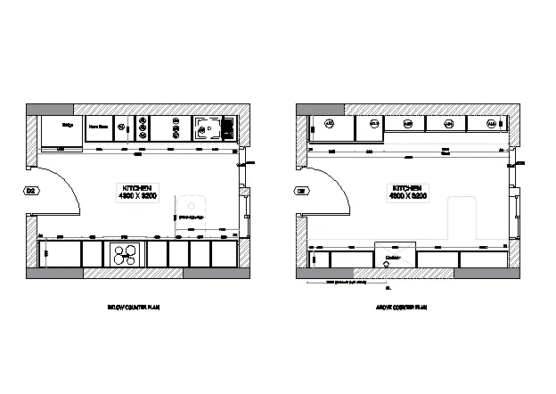
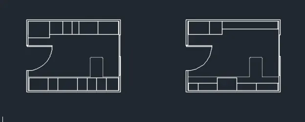
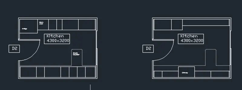
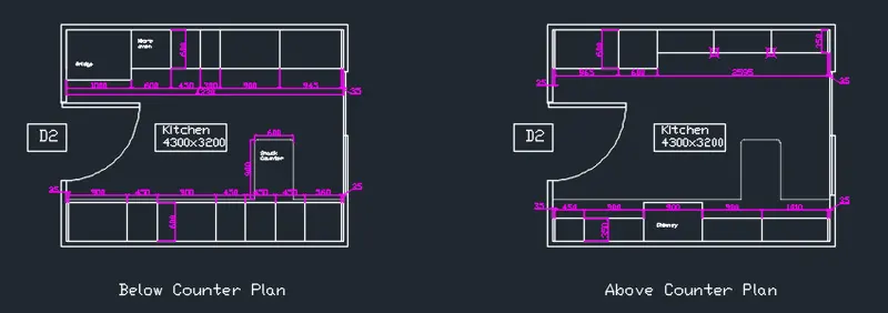
Procedure:
- Draw the outermost boundary of the kitchen using the rectangle command.
- Give an offset of 35 to the inner side of the rectangle denoting the wall thickness.
- Draw the door using trim, line, offset, and arc commands.
- Draw the counters in the kitchen.
- Once the below counter plan is drawn, copy the plan and do the editing required for the above counter plan.
- Give the dimensions and labeling where ever required.
Results:
- The required plan according to the dimensions is formed.
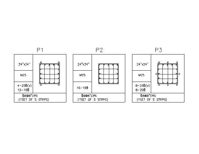
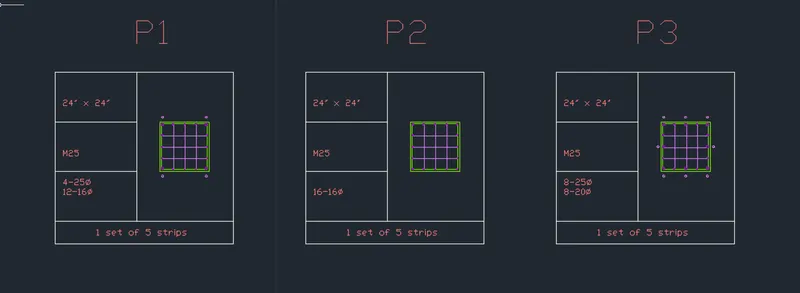
AIM: Sketch the column details as shown in Figure. Insert dimensions and text in the figure. Refer to the bar sizes from the schedule.
8mm ---- 0.31 Inches
25mm--- 1 inch
16mm—0.62 inches
Procedure:
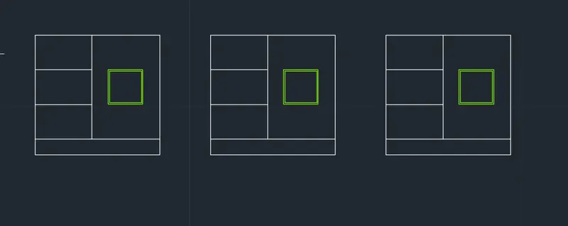
- Draw a square of 2' x 2' size and apply an offset of 1" to it.
- Draw a table as required using the line and offset tool.
- Draw the bars and distribution steel.
- Give the dimensions and labeling where ever required.
Results:
- The required plan according to the dimensions is formed.
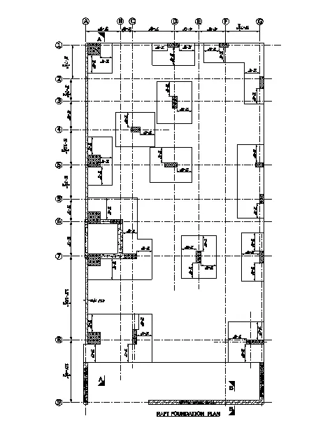
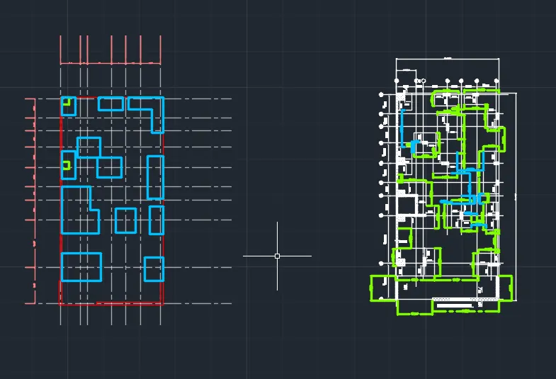
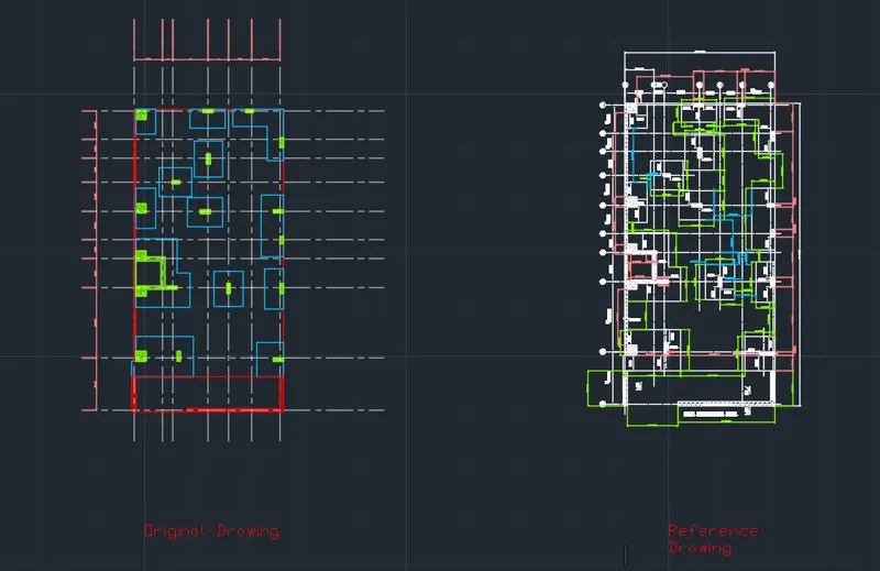
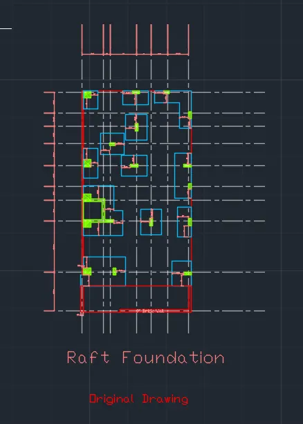
AIM: Draw the Raft Layout as shown in the Figure. Assume the column size as per your knowledge. You can take sizes like 24”x24”, 9” x 24”, 9” x 18”, and 9’ x 24”. You can import the raft_foundation.pdf to ensure the missing dimensions.

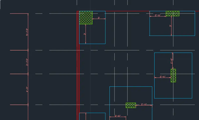
Procedure:
- Import the floor plan pdf.
- Using the reference of the imported plan draw a copy of the plan.
- Firstly, start with the grid lines by using xline command.
- Then draw the plan according to the dimensions reference taken from the reference plan.
- Apply hatch to the columns, brick, and concrete walls.
- Give the dimensions and labeling where ever required.
Results:
- The required plan according to the dimensions is formed.