Creating a Wardrobe detailed drawing, Floor Plan, Kitchen Layout and Column Detail using AutoCad
1. AIM:
To Create a Cabinet drawing by using Autocad
INTRODUCTION:
- To Create a Cabinet drawing by using a various command.
- Now we see the Step by Step Procedure to create a Drawing.
CABINET DRAWING:
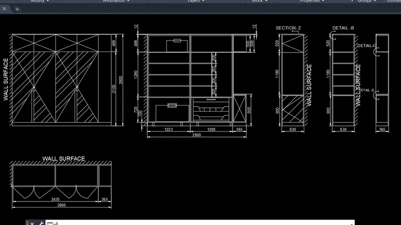
1. we create a Cabinet Drawing elevation, plan, and section
2. we need to draw the plan as per dimension
3. Click 'REC' command to draw the outer of the plan
4. After Click 'L' command to draw the center line
5. and click 'OFF' command to offset the line.
6. Click 'DIM' dimension and show the dimension
7. continue to draw Elevation drawing
8. Click 'REC' command to draw outer of the elevation.
9. After Click ' L ' line command to draw the center line.
10. And click 'OF' offset command to offset the line
11. Click 'H' hatch command to hatch the point
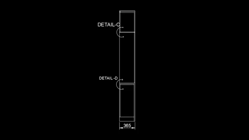
12. Next we need to draw the section 1 & 2 Drawings
13. Draw the section as per elevation drawing.
14. Click 'REC' command to draw outer of elevation.
15. After click 'L' line command to draw the center line.
16. And click 'OFF' offset command to offset the line.
17. Click 'HAT' hatch command to hatch the point.
18. click 'DIM' dimension and show the dimension.
19. and show the details mark.
20. also insert text with the help of Dtext command or single line text.
21. Click 'DTEXT' command to create the text.
22. Click 'SAVE' command to save the text.
Image:01
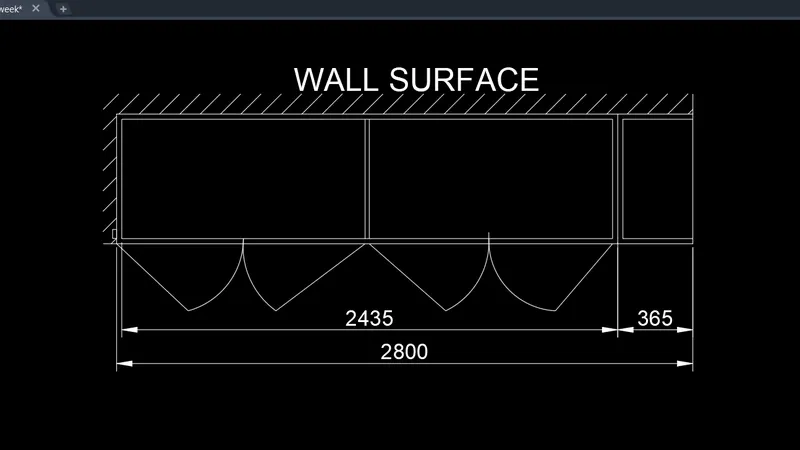
Image:02
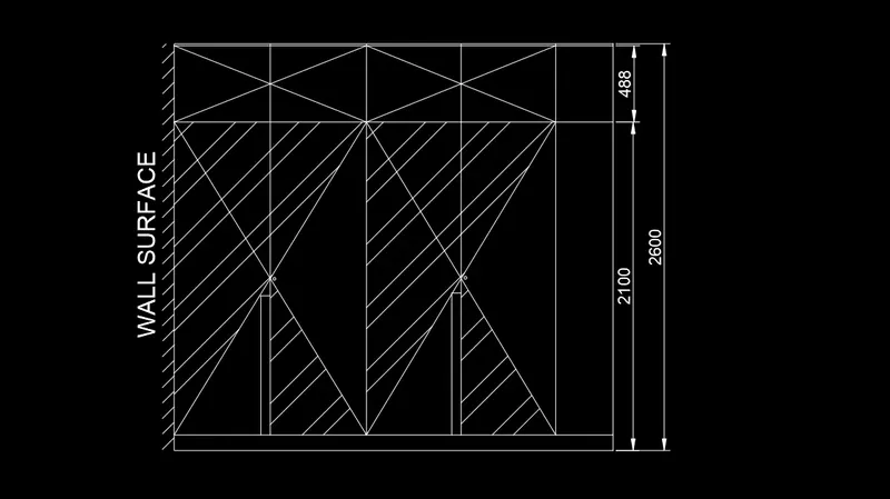
Image:03
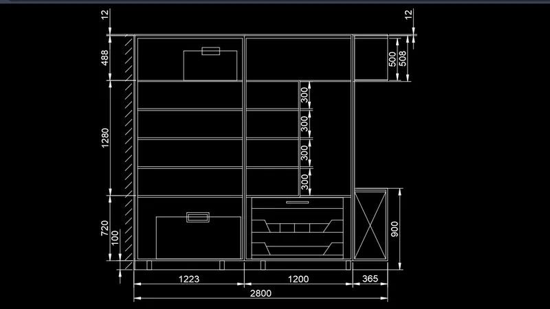
Image:04
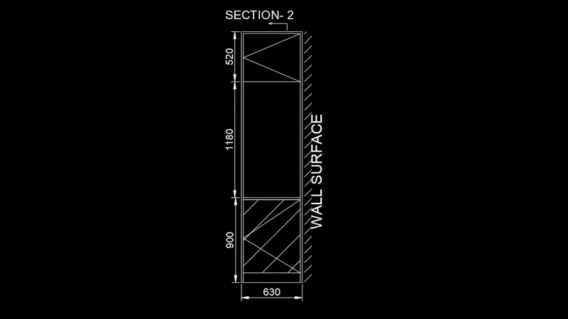
Image:05
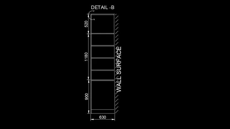
Image:06
RESULT:
2. AIM: To create a Kitchen plan by using autocad.
KITCHEN PLAN:
- In this drawing we create a kitchen plan.
- Now we can see the command used for this drawing as step by step .
1. First we need to study the plan and get planed to draw
2. First we need to start from left hand side of the plan.
3. Click REC command to create the outer wall.
4. Click 'XL'-V (vertical line) command to start draw.
5. And 'OFF' offset as per plan dimension
6. First we need to create a inner wall of drawing.
7. Then offset the room size as per dimension given as per plan
8. Click 'TR' trim command trim the extended line.
9. Then 'EX' entend command to extend line upto the second line.
10. And draw the DOOR with the help of Circle command .
11. And first to draw hinge .25" and draw over a circle.
12. Draw straight line to centre to centre of the line.
13. Finally trim the circle and create a door.
14. Then Click HATCH option to outer wall.
15. Click 'TEXT' option to create a room name as a text layer
16. After complete a drawing we need show to dimension of kitchen plan.
17. Click 'DIM' command to create a dimension.
IMAGE 01:
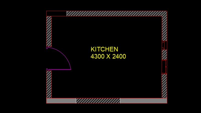
IMAGE 02:
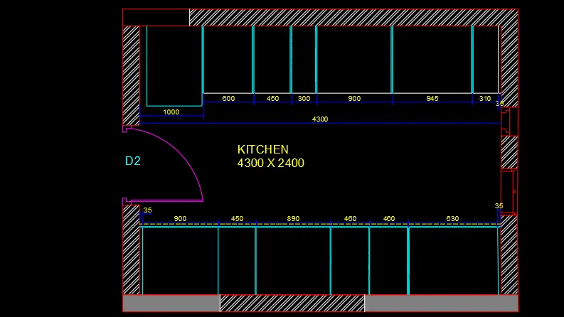
IMAGE 03:
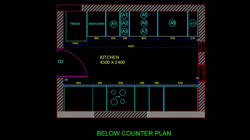
IMAGE 04:
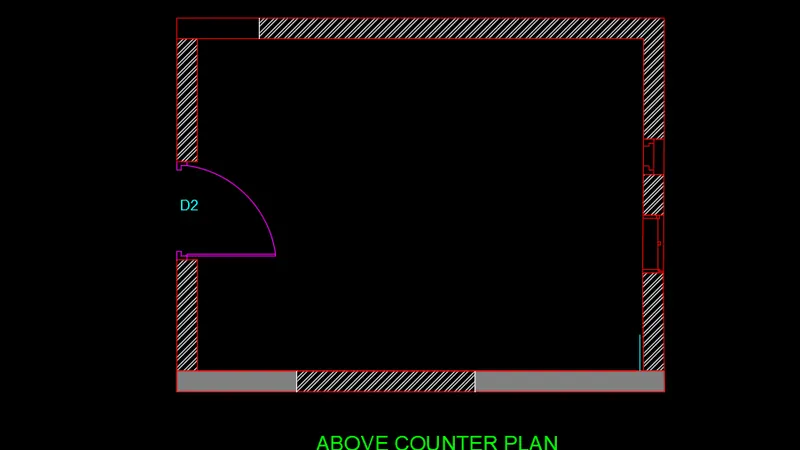
IMAGE 05:
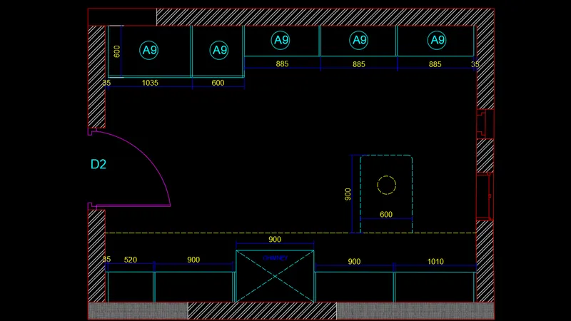
IMAGE 06:
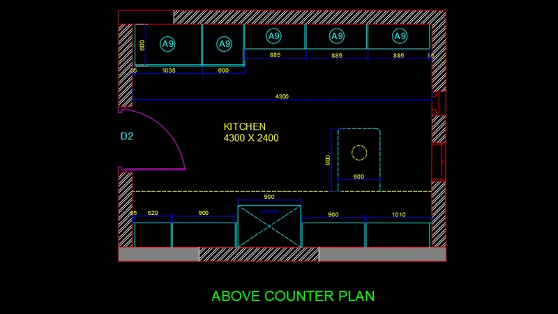
IMAGE 07:
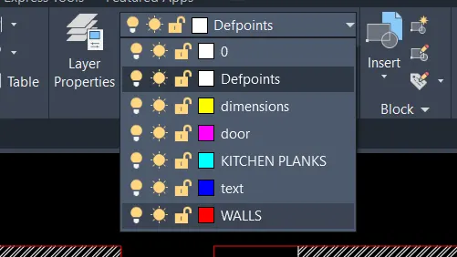
RESULT:
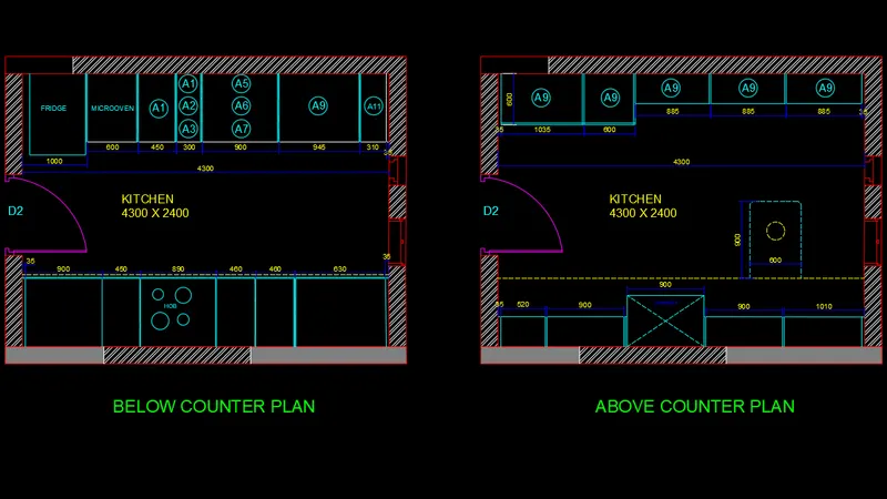
Therefore, the required kitchen plan was drawn.
3. AIM:
To create a Column schedule by using Auto cad
INTRODUCTION:
- To Create a Column Schedule (P1,P2,P3) by using a Dtext
- Now we see the step by step procedure to create a text
Column schedule:
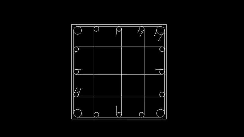
1. we create a column schedule with the help of rectangle
2. Click the REC rectangle command to draw the column
3. Then 'OFF' offset the rectangle to 40mm cover to inner of column
4. And to start the reinforcement placing the dia as per details
5. Draw the column "circle" command used to create
6. Then draw the stirrups line & fillet command used to draw.
7. Draw the 3 types of column in different reinforcement.
8. Also insert text with help of DText command or single line text.
9. Use the font name: Romans;height 4" and justify Left
10. First create a tabular column to type the name.
11. Click " DTEXT" command to create the text
12. and type the text as per dimension
13. And click "save" command to save the text.
IMAGE - 01
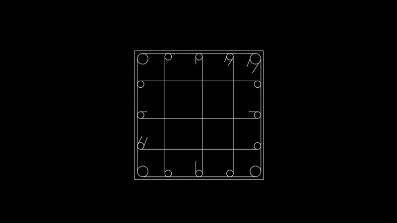
IMAGE - 02
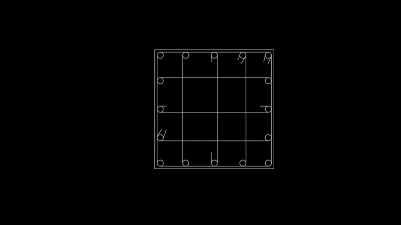
IMAGE - 03
RESULT:
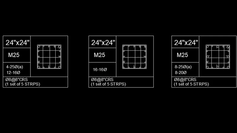
- The required column schedule was prepared by using autocad
4. AIM: To create the RAFT footing.
INTRODUCTION:
- In this we create a Raft footing.
- Now we can see the command used for this drawing as step by step.
STEP:
1. First we need to study the raft footing and get planed to draw.
2. Create the grid line as per drawing.
3. Click 'XL' line as vertical and horizontal line.
4. And use the 'TR' trim command and cut the line as per dimension
5. Then we create the column footing in the center of line.
6. Click 'REC' rectangle command to draw the column as per dimension
7. And 'HAT' hatch command to pick inner point of the column
8. The outer footing size is mention in drawing as per we need to draw.
9. After we need to draw as per column size various footing size.
10. Finally complete the raft footing drawing we need to show the dimension.
11. Click "DIM" command to create a dimension
IMAGE: 01
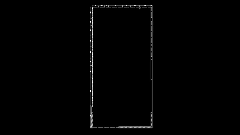
IMAGE: 02
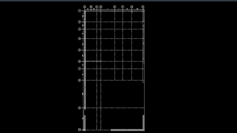
IMAGE :03
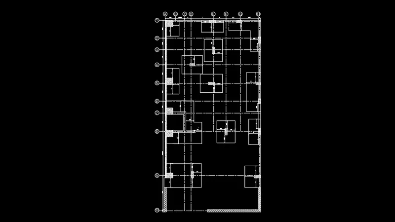
IMAGE: 04
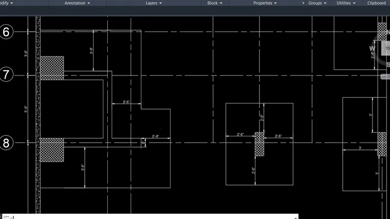
IMAGE: 05
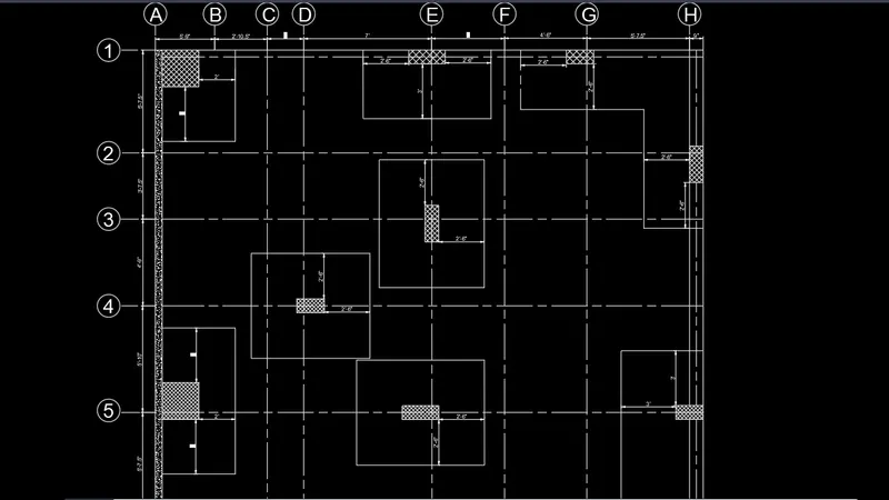
IMAGE: 06
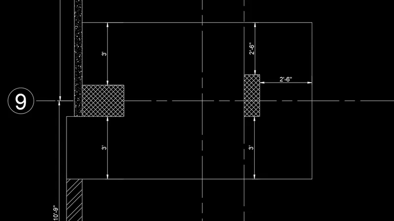
RESULT:
Thus we got required Raft foundation drawing by autocad.
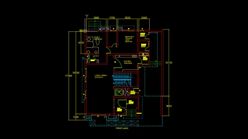
Q2. Draw the floor plan as shown in the Figure. Use the proper drafting tools to sketch the plan. Do not hatch or draw the furniture. You need to draw the floor plan with the following:
Note: You can also import the Floor_Plan.pdf into your current drawing and start working on the project. You need to scale the imported pdf file using reference option. All dimensions are in mm.
- Walls (Exterior and Interior)
Wall Thickness: Exterior Wall- 230mm, Interior Wall: 150 mm (Wherever Required)
- Doors and Windows: Assume the size of the doors and window.
1 Stairs: Tread-300mm 2. Riser-150mm
- Insert Text wherever required
- Insert the dimensions using proper dimension techniques
IMAGE : 01
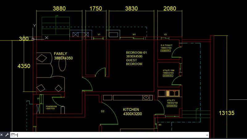
IMAGE : 02
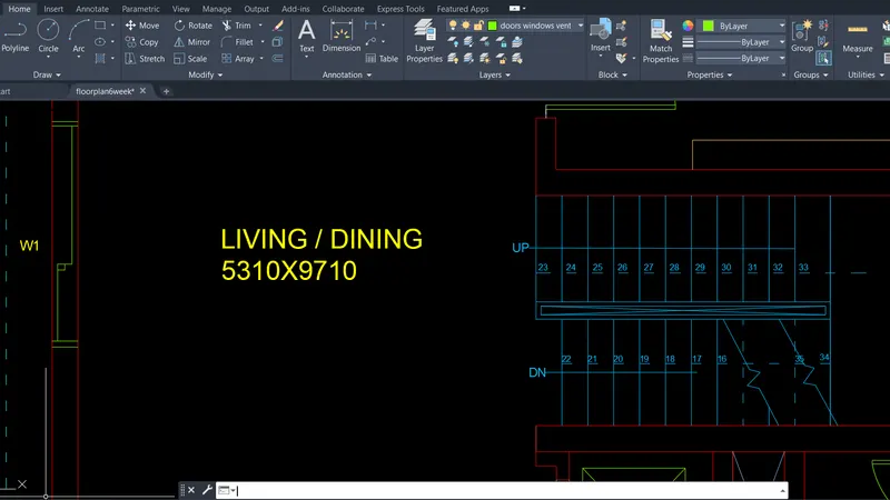
IMAGE : 03
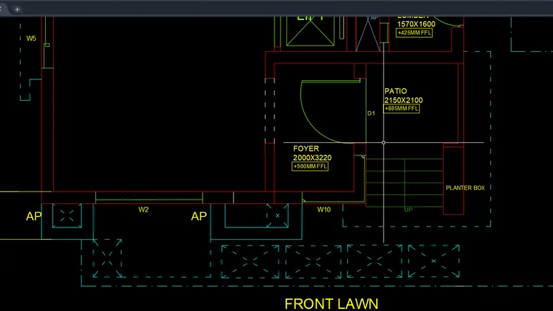
IMAGE : 04
Thus, the resultant drawing was drawn.